ABB Medium Voltage Indoor Fuses - ABB CEF-S High Voltage Current Limiting Fus...
Depositiondata
1. 6
TECHNICAL
DEPOSITION DATA
5571300 WELDER (1300 935 337)
Copyright Produced with the permission of CIGWELD
DEPOSITIONDATA
DEPOSITION RATES, ELECTRODE EFFICIENCY, AND ELECTRODE WELD METAL RECOVERY!
WHAT ARE THE DIFFERENCES?
Deposition Rates
The deposition rate of a welding consumable (electrode, wire or rod) is the rate at which weld metal is deposited (melted) onto a metal surface.
Deposition rate is expressed in kilograms per hour (kg/hr).
Depositionrateisbasedoncontinuousoperation,notallowingforstopsandstartssuchas,electrodechangeovers,chippingslag,cleaningspatter,
machine adjustments or other reasons.
When welding current is increased so to does the deposition rate. When electrical stick out is increased in the case of GMAW and FCAW the
deposition rate will also increase.
Deposition rates are calculated by doing actual welding tests, and the following shows the formula for measuring deposition rates.
Deposition Rate = Weight of test plate before welding - Weight of test plate after welding ÷ Measured period of time (normally 60 seconds).
e.g. Plate before welding: 2kg - 2.95kg Plate after welding = 95grams, welded in 60 seconds. 95grams x 60/1000 = 5.7kg/hr.
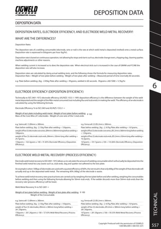
ELECTRODE EFFICIENCY (DEPOSITION EFFICIENCY)
Technically to ISO 2401-1972 electrode efficiency (AS/NZS 1553.1: 1995 deposition efficiency) is the difference between the weight of the weld
metaldepositedandtheweightofthefillermetalconsumed(notincludingfluxandstubends)inmakingtheweld. Theefficiencyofanelectrodeis
calculated by using the following formula;
Electrode Efficiency % to ISO 2401and AS/NZS 1553.1 =
Weight of test plate including weld metal - Weight of test plate before welding X 100
Mass of the Core Wire of 5 electrodes - Weight of core wire of the 5 stub ends
e.g. Ferrocraft 22 Ø3.2mm x 380mm.
Plate before welding: 2kg - 2.167kg Plate after welding = 167grams,
weightoffive(5)electrodecorewires,Ø3.2mmx380mmlongbeforewelding
= 124grams,
weightoffive(5)electrodestubends,Ø3.2mmx50mmlongafterwelding=
16.3grams,
167grams ÷ 107.7grams x 100 = 155.06% Electrode Efficiency (Deposition
Efficiency).
e.g. Satincraft 13 Ø4mm x 380mm.
Plate before welding: 2kg - 2.15kg Plate after welding = 150grams,
weightoffive(5)electrodecorewires,Ø4mmx380mmlongbeforewelding=
188grams,
weight of five (5) electrode stub ends, Ø4mm x 50mm long after welding =
24.7grams,
150grams ÷ 163.3grams x 100 = 91.85% Electrode Efficiency (Deposition
Efficiency).
ELECTRODE WELD METAL RECOVERY (PROCESS EFFICIENCY)
ElectrodeweldmetalrecoverytoISO2401-1972allowsustocalculatetheamountofweldingconsumablewhichwillactuallybedepositedintothe
finished weld metal less any waste such as, stub ends, slag and spatter not adhered to the test plate.
Anexampleiswhen100kgsofelectrodesareusedwithaquotedefficiencyof60%,thenetresultisthatonly60kgoftheweightofthatelectrodewill
actually end up in the deposited weld metal. The remaining 40% (40kg) of the electrode is waste.
Toachieveweldmetalrecoveryratespracticaltestsarecarriedoutbyweighingthetestplatebeforeandafterwelding,weighingtheconsumables
before welding and then using the following formula allowing for 50mm stub ends. If the welder discards more than 50mm stub ends than the
recovery rate (process efficiency) will be lower.
Weld Metal Recovery % to ISO 2401 =
Weight of test plate before welding - Weight of test plate after welding X 100
Weight of the Consumable
e.g. Satincraft 13 Ø4mm x 380mm.
Plate before welding: 2kg - 2.15kg Plate after welding = 150grams,
weight of five (5) electrodes, Ø4mm x 380mm long before welding =
261.20grams,
150grams ÷ 261.20grams x 100 = 57.43% Weld Metal Recovery (Process
Efficiency).
e.g. Ferrocraft 22 Ø3.2mm x 380mm.
Plate before welding: 2kg - 2.167kg Plate after welding = 167grams,
weight of five (5) electrodes, Ø3.2mm x 380mm long before welding =
281.50grams,
167grams ÷ 281.50grams x 100 = 59.33% Weld Metal Recovery (Process
Efficiency).
2. 6
DEPOSITION DATA
TECHNICAL
558 SPW GROUP PTY LTD
Copyright Produced with the permission of CIGWELD
GENERAL PROCESS EFFICIENCIES
Welding Process Average Efficiency
Gas Tungsten Arc Welding (GTAW) & Oxy-Acetylene Welding (OAW) 100%
Manual Metal Arc Welding (MMAW) 60%
Gas Metal Arc Welding (GMAW) Short Arc, Ar + 25% CO2 92%
Gas Metal Arc Welding (GMAW) Spray Arc, Ar + 25% CO2 95%
Gas Metal Arc Welding (GMAW) Pulse Arc, Ar + 25% CO2 98%
Flux Cored Arc Welding (FCAW) E70T-4 types, self shielded 82%
Flux Cored Arc Welding (FCAW) E71T-1 types, Ar + 25% CO2 85%
Flux Cored Arc Welding (FCAW) E70T-5 types, Ar + 25% CO2 88%
Flux Cored Arc Welding (FCAW) E70C-6M types, Ar + 25% CO2 92%
Cobalarc Flux Cored Hardfacing Wires Gas shielded 80%
GMAWandFCAWaverageefficienciescanvaryinresultdependingupontheshieldinggasesused,machinesettings,stickout,spatterlosses,wiresnipedoffbeforestartsetc.
CONSUMABLE WEIGHT CALCULATION
Required Welding (Area x 1 in M x 7900 KG)
Consumable In KG = See detail below X Length In M
(Deposition efficiency as a percentage / 100)
See detail above
The Above formula will calculate your required weld metal using a particular welding consumable process in KG per Metre of weld.
(Area x 1 in M x 7900 KG)
Areacanbecalculatedusingtheequationsonpage560.Bymultiplyingtheareaby1willgiveusavolumeofweldmetalrequiredforevery1metreofweld.Wethen
multiply the volume by the weight of steel at 7900 KG per Cubic Metre to give us a weight in KG per Metre of weld.
Foreaseofcalculationwehaveincludedaseriesoftablesonpage556&557.Thiscanbeusedintheequationaboveinplaceof(Areax1inMx7900KG).Thetables
can be used as follows.
SimplyselecttheshapesfromtheabovesamplesandreadtherelevanttablesonthefollowingpagetodeterminetheweightofweldmetalinKGforeveryMof
weld.Addeachoftheshapestogetherthatmakeupyourweldandinsertintheequationaboveinplaceof(Areax1inMx7900KG). Youcanadd2xTriangles
togethertogetyourtotalweldweightforabuttweldwith2preps.IntheTriangletablewehaveincludedthelegthofthetopoftheweldsoyoucancalculatethe
width of the Cap.
(Deposition efficiency as a percentage / 100) See detail above
Deposition efficiency is expressed as a percentage on this page above. Divide this percentage by 100 to convert to a decimal.
TRIANGLE
T
W
X
Where
T = Plate Thickness X = Bevel angle
W = Width for Cap
RECTANGLE
T
WWhere
T = Plate Thickness W = Width
TRIANGLE Weight of Weld Metal in KG/M of weld
For Filet calculations use 45 degrees and F being the Fillet length
X (Angle in degrees)
15 20 30 45 60 70
KG/M W KG/M W KG/M W KG/M W F KG/M W KG/M W
3.15 0.01 0.8 0.01 1.1 0.02 1.8 0.04 3.2 6.0 0.07 5.5 0.11 8.7
4.2 0.02 1.1 0.03 1.5 0.04 2.4 0.07 4.2 8.0 0.12 7.3 0.19 11.5
5.25 0.03 1.4 0.04 1.9 0.06 3.0 0.11 5.3 10.0 0.19 9.1 0.30 14.4
6 0.04 1.6 0.05 2.2 0.08 3.5 0.14 6.0 11.4 0.25 10.4 0.39 16.5
8 0.07 2.1 0.09 2.9 0.15 4.6 0.25 8.0 15.2 0.44 13.9 0.69 22.0
10 0.11 2.7 0.14 3.6 0.23 5.8 0.40 10.0 19.0 0.68 17.3 1.09 27.5
12 0.15 3.2 0.21 4.4 0.33 6.9 0.57 12.0 22.8 0.99 20.8 1.56 33.0
14 0.21 3.8 0.28 5.1 0.45 8.1 0.77 14.0 26.7 1.34 24.2 2.13 38.5
16 0.27 4.3 0.37 5.8 0.58 9.2 1.01 16.0 30.5 1.75 27.7 2.78 44.0
18 0.34 4.8 0.47 6.6 0.74 10.4 1.28 18.0 34.3 2.22 31.2 3.52 49.5
20 0.42 5.4 0.58 7.3 0.91 11.5 1.58 20.0 38.1 2.74 34.6 4.34 54.9
22 0.51 5.9 0.70 8.0 1.10 12.7 1.91 22.0 41.9 3.31 38.1 5.25 60.4
24 0.61 6.4 0.83 8.7 1.31 13.9 2.28 24.0 45.7 3.94 41.6 6.25 65.9
25 0.66 6.7 0.90 9.1 1.43 14.4 2.47 25.0 47.6 4.28 43.3 6.78 68.7
26 0.72 7.0 0.97 9.5 1.54 15.0 2.67 26.0 49.5 4.62 45.0 7.34 71.4
28 0.83 7.5 1.13 10.2 1.79 16.2 3.10 28.0 53.3 5.36 48.5 8.51 76.9
30 0.95 8.0 1.29 10.9 2.05 17.3 3.56 30.0 57.1 6.16 52.0 9.77 82.4
32 1.08 8.6 1.47 11.6 2.34 18.5 4.04 32.0 60.9 7.01 55.4 11.1 87.9
34 1.22 9.1 1.66 12.4 2.64 19.6 4.57 34.0 64.7 7.91 58.9 12.5 93.4
36 1.37 9.6 1.86 13.1 2.96 20.8 5.12 36.0 68.5 8.87 62.4 14.1 98.9
38 1.53 10.2 2.08 13.8 3.29 21.9 5.70 38.0 72.3 9.88 65.8 15.7 104
40 1.69 10.7 2.30 14.6 3.65 23.1 6.32 40.0 76.1 10.9 69.3 17.4 110
RECTANGLE Weight of Weld Metal in KG/M of weld
W (Width in mm)
1 2 3 4 5 6 7 8 9 10 12 15 20
6 0.05 0.09 0.14 0.19 0.24 0.28 0.33 0.38 0.43 0.47 0.57 0.71 0.95
8 0.06 0.13 0.19 0.25 0.32 0.38 0.44 0.51 0.57 0.63 0.76 0.95 1.26
10 0.08 0.16 0.24 0.32 0.40 0.47 0.55 0.63 0.71 0.79 0.95 1.19 1.58
12 0.09 0.19 0.28 0.38 0.47 0.57 0.66 0.76 0.85 0.95 1.14 1.42 1.90
14 0.11 0.22 0.33 0.44 0.55 0.66 0.77 0.88 1.00 1.11 1.33 1.66 2.21
16 0.13 0.25 0.38 0.51 0.63 0.76 0.88 1.01 1.14 1.26 1.52 1.90 2.53
18 0.14 0.28 0.43 0.57 0.71 0.85 1.00 1.14 1.28 1.42 1.71 2.13 2.84
20 0.16 0.32 0.47 0.63 0.79 0.95 1.11 1.26 1.42 1.58 1.90 2.37 3.16
22 0.17 0.35 0.52 0.70 0.87 1.04 1.22 1.39 1.56 1.74 2.09 2.61 3.48
24 0.19 0.38 0.57 0.76 0.95 1.14 1.33 1.52 1.71 1.90 2.28 2.84 3.79
25 0.20 0.40 0.59 0.79 0.99 1.19 1.38 1.58 1.78 1.98 2.37 2.96 3.95
26 0.21 0.41 0.62 0.82 1.03 1.23 1.44 1.64 1.85 2.05 2.46 3.08 4.11
28 0.22 0.44 0.66 0.88 1.11 1.33 1.55 1.77 1.99 2.21 2.65 3.32 4.42
30 0.24 0.47 0.71 0.95 1.19 1.42 1.66 1.90 2.13 2.37 2.84 3.56 4.74
32 0.25 0.51 0.76 1.01 1.26 1.52 1.77 2.02 2.28 2.53 3.03 3.79 5.06
34 0.27 0.54 0.81 1.07 1.34 1.61 1.88 2.15 2.42 2.69 3.22 4.03 5.37
A(PlateThicknessinmm)T(PlateThicknessinmm)
F
3. 6
TECHNICAL
DEPOSITION DATA
5591300 WELDER (1300 935 337)
Copyright Produced with the permission of CIGWELD
CIGWELD SOLID AND FLUX CORED WIRES, DEPOSITION AND WELD METAL RECOVERY RATES
The following Table lists some popular CIGWELD consumables and their Deposition and Weld Metal Recovery Rates:
CIGWELD Product Size (mm) Volts Amps WFS m/min Deposition Rate kg/hr Weld Metal Recovery
Autocraft LW1-6 0.8 20 150 12.0 2.5 96%
Autocraft LW1-6 0.9 26 180 12.0 3.1 96%
Autocraft LW1-6 1.0 28 240 13.5 4.8 95%
Autocraft LW1-6 1.2 32 300 10.8 5.6 97%
Autocraft Silicon Bronze 0.9 24 180 13.2 3.2 95%
Autocraft 316LSi 0.9 22 180 10.0 2.8 97%
Autocraft 316LSi 1.2 26 250 8.5 4.4 98%
Autocraft AL5356 1.0 22 180 16.3 1.5 90%
Autocraft AL5356 1.2 24 220 14.0 2.5 92%
Satin-Cor XP 1.6 28 300 5.5 4.3 86%
Satin-Cor XP 1.6 29 350 6.5 5.4 87%
Satin-Cor XP 1.6 30 400 7.0 6.0 89%
Satin-Cor XP 2.4 30 400 4.2 5.7 85%
Satin-Cor XP 2.4 31 450 5.0 6.8 86%
Satin-Cor XP 2.4 32 500 6.0 8.2 90%
Verti-Cor 3XP 1.2 25 200 6.7 2.7 86%
Verti-Cor 3XP 1.2 26 250 9.9 3.8 84%
Verti-Cor 3XP 1.2 28 320 15.0 5.9 88%
Verti-Cor 3XP 1.6 27 300 6.2 4.1 86%
Verti-Cor 3XP 1.6 28 350 9.5 6.4 81%
Verti-Cor 3XP 1.6 29 400 12.0 8.1 88%
Metal-Cor XP 1.2 26 250 10.0 5.0 92%
Metal-Cor XP 1.6 28 350 6.6 5.6 94%
Supre-or 5 1.2 22 170 7.8 2.3 86%
Supre-Cor 5 1.6 26 320 5.9 3.3 89%
Tensi-Cor 110TXP 1.6 28 280 5.0 3.0 88%
Tensi-Cor 110TXP 2.4 29 400 3.8 5.8 90%
Shieldcrome 309LT 1.2 26 190 11.4 3.7 84%
Shield-Cor 4XP 2.4 29 375 5.4 7.0 84%
Shield-Cor 4XP 3.0 30 500 2.9 6.7 86%
Shield-Cor 15 0.9 17 120 3.9 0.7 75%
Shield-Cor 11 1.2 17 150 3.0 1.0 80%
Theinformationprovidedinthistableisbasedonweldingwithconstantvoltage(C.V.)GMAWeldingmachines.Resultsmayvaryandareinfluencedonthejobby
shielding gases used, machine settings, stick out, spatter losses, wire sniped off before starts etc.
MANUAL ARC ELECTRODE CONSUMPTION CALCULATOR GUIDE
Basis of Calculations
Electrode requirements have been calculated as follows:
Where M = Mass of electrodes required
D = Mass of weld metal to be deposited
E = Proportion of electrode lost
M = D
1 - E
Toarriveatthemassofweldmetaltobedepositeditisnecessarytocalculate
first the volume of metal to be added (area of the cross section of the weld
multiplied by the length). This volumetric value is converted to mass by
multiplying by the factor 0.0079 kilograms per cubic centimetre for steel.
Instructions for Use of this Data
The following tables provide data on the approximate mass in kilograms
required of the different types of electrodes for welding the various weld
jointsusedthroughoutindustrytoday.Thisdatawillaidinestimatingmaterial
requirements and costs. The basis for the following tabulations is given
below. Where variations from the given conditions or joint preparations are
encountered,adjustmentsinthetabulatedvaluesmustbemadetocompensate
for such differences.
CAP Weight of Weld Metal in KG/M of weld
CH (Cap Height in mm)
1 1.5 2 2.5 3 4 5 6
5 0.03 0.04 0.06 0.07 0.09 0.12 0.15 0.18
6 0.04 0.05 0.07 0.09 0.11 0.14 0.18 0.21
7 0.04 0.06 0.08 0.10 0.12 0.17 0.21 0.25
8 0.05 0.07 0.09 0.12 0.14 0.19 0.24 0.28
10 0.06 0.09 0.12 0.15 0.18 0.24 0.30 0.36
12 0.07 0.11 0.14 0.18 0.21 0.28 0.36 0.43
14 0.08 0.12 0.17 0.21 0.25 0.33 0.41 0.50
15 0.09 0.13 0.18 0.22 0.27 0.36 0.44 0.53
16 0.09 0.14 0.19 0.24 0.28 0.38 0.47 0.57
18 0.11 0.16 0.21 0.27 0.32 0.43 0.53 0.64
20 0.12 0.18 0.24 0.30 0.36 0.47 0.59 0.71
22 0.13 0.20 0.26 0.33 0.39 0.52 0.65 0.78
24 0.14 0.21 0.28 0.36 0.43 0.57 0.71 0.85
25 0.15 0.22 0.30 0.37 0.44 0.59 0.74 0.89
26 0.15 0.23 0.31 0.39 0.46 0.62 0.77 0.92
28 0.17 0.25 0.33 0.41 0.50 0.66 0.83 1.00
30 0.18 0.27 0.36 0.44 0.53 0.71 0.89 1.07
35 0.21 0.31 0.41 0.52 0.62 0.83 1.04 1.24
40 0.24 0.36 0.47 0.59 0.71 0.95 1.19 1.42
CAP
CH
CW
Where
CH = Cap Height CW = Cap Width
CW(CapWidthinmm)
4. 6
DEPOSITION DATA
TECHNICAL
560 SPW GROUP PTY LTD
Copyright Produced with the permission of CIGWELD
SQUARE BUTT JOINTS, WELDED BOTH SIDES
Joint Dimensions kg of electrodes per linear metre of weld* (Approx.) kg of weldmetal deposited per liner metre of weld (Approx.)
Plate Thickness Root Gap (R) With Reinforcement** With Reinforcement**
3mm 0 0.23 0.14
1mm 0.26 0.16
5mm 1mm 0.38 0.23
1.6mm 0.41 0.25
6mm 1.6mm 0.48 0.29
2.5mm 0.56 0.34
* Includes spatter losses and 50mm stub end loss.
** Height of Reinforcement = 2mm.
HORIZONTAL-VERTICAL (HV) FILLET WELDS
Fillet Weld leg length Dimensions kg of electrodes per linear metre of weld* (Approx.) kg of weldmetal deposited per iner metre of weld (Approx.)
3mm 0.06 0.04
5mm 0.16 0.10
6mm 0.24 0.14
8mm 0.42 0.25
10mm 0.65 0.39
12mm 0.95 0.57
16mm 1.68 1.01
20mm 2.62 1.57
25mm 4.10 2.46
* Fillet weld figures are calculated based on true mitre fillets. Convex or overwelded fillets can increase these figures by 33% or more.
SINGLE VEE BUTT JOINTS, (SINGLE GROOVE BUTTS)
Fillet Weld leg length Dimensions kg of electrodes per linear metre of weld* (Approx.) kg of weldmetal deposited per iner metre of weld (Approx.)
Plate Root Root With Reinforcement** With Reinforcement**
Thickness Face (F) Gap (R)
6mm 1.6mm 1.6mm 0.39 0.23
8mm 1.6mm 1.6mm 0.63 0.38
10mm 1.6mm 1.6mm 0.87 0.52
12mm 3mm 3mm 1.33 0.80
16mm 3mm 3mm 2.22 1.33
20mm 3mm 3mm 3.37 2.02
25mm 3mm 3mm 5.14 3.08
* Includes spatter, 50mm stub ends and back gouging losses.
** Height of Reinforcement = 2mm.
DOUBLE VEE BUTT JOINTS, WELDED BOTH SIDES (DOUBLE GROOVE BUTTS)
Fillet Weld leg length Dimensions kg of electrodes per linear metre of weld* (Approx.) kg of weldmetal deposited per iner metre of weld (Approx.)
Plate Root Root With Reinforcement** With Reinforcement**
Thickness Face (F) Gap (R)
12mm 1.6mm 1.6mm 0.92 0.55
16mm 1.6mm 1.6mm 1.46 0.88
20mm 1.6mm 1.6mm 2.12 1.27
25mm 3mm 3mm 3.33 2.00
* Includes spatter, 50mm stub ends and back gouging losses.
** Height of Reinforcement = 2mm.
5. 6
TECHNICAL
DEPOSITION DATA
5611300 WELDER (1300 935 337)
Copyright Produced with the permission of CIGWELD
1. GAS METAL ARC WELDING (GMAW - MIG) WIRES FOR MILD AND LOW ALLOY STEELS
WIRE SIZE (mm) 0.6 0.8 0.9 1.2 1.6
gms of wire per metre 2.2 4 4.85 8.5 15.7
metres of wire per kg 450 254 200 113 63
2. FLUX CORED ARC WELDING (FCAW) WIRES FOR MILD AND LOW ALLOY STEELS
WIRE SIZE (mm) 1.2 1.6 2.0 2.4
gms of wire per metre 7.5 13 21 28.5
metres of wire per kg 132 77 50 36
3. SUBMERGED ARC WELDING (SAW) WIRES FOR MILD AND LOW ALLOY STEELS
WIRE SIZE (mm) 2.4 3.2
gms of wire per metre 35.5 63
metres of wire per kg 28 16
4. STAINLESS STEEL GAS METAL ARC WELDING (GMAW - MIG) WIRES
WIRE SIZE (mm) 0.9 1.2 1.6
gms of wire per metre 5.1 9 16
metres of wire per kg 198 111 63
5. ALUMINIUM GAS METAL ARC WELDING (GMAW - MIG) WIRES
WIRE SIZE (mm) 0.9 1.2 1.6
gms of wire per metre 1.7 3.1 5.4
metres of wire per kg 582 327.5 184
6. AUTOPAK GAS METAL ARC WELDING (GMAW - MIG) WIRES
WIRE SIZE (mm) 0.9 1.0 1.2 1.6
gms of wire per metre 4.85 6.1 8.5 15.7
km of wire / 300kg Pack 62 49 35 16 (250kg Pack)