Modeling masonry in Revit
•
7 j'aime•8,660 vues

This document provides guidance for modeling masonry buildings in Autodesk Revit. It includes contributions from industry experts who developed building models to demonstrate masonry modeling techniques in Revit. The guide covers topics such as wall modeling fundamentals, challenges of modeling masonry, masonry features that can be modeled, and recommendations to improve masonry modeling in Revit. It is intended to help designers effectively use BIM with masonry and also guide future development of Revit and associated tools.

Recommandé
Contenu connexe
Tendances
Tendances (20)
En vedette
Similaire à Modeling masonry in Revit
Similaire à Modeling masonry in Revit (9)
Plus de Huytraining
Plus de Huytraining (20)
Dernier
Dernier (20)
Modeling masonry in Revit
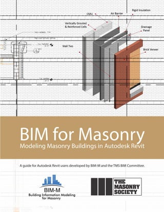
- 1. BIM for MasonryModeling Masonry Buildings in Autodesk Revit A guide for Autodesk Revit users developed by BIM-M and the TMS BIM Committee.
- 2. BIM for Masonry Modeling Masonry Buildings in Autodesk Revit Published by The Masonry Society 105 South Sunset Street, Suite Q Longmont, CO USA 80501- 6172 Copyright © 2016 The Masonry Society February 2016, First Edition Users are free to read, download, distribute, copy, print, search, or link to the full text for any non- commercial purpose. However, all intellectual property rights are reserved. DISCLAIMER OF LIABILITY FOR USE This publication was produced as a TMS Independent Author Publication. The opinions and statements presented herein are solely those of the authors. The Masonry Society is not responsible for the statements or opinions of the authors, nor for any errors or omissions that this text may contain. The Masonry Society disclaims any and all responsibility for the application of the information. TMS Order No. TMS-5901-16
- 3. BIM‐M EXECUTIVE COMMITTEE International Masonry Institute: David Sovinski International Union of Bricklayers and Allied Craftworkers: James Boland National Concrete Masonry Association Foundation: Robert Thomas Mason Contractors Association of America: Jeffrey Buczkiewicz Edward Davenport Western States Clay Products Association: Jeffrey Elder The Masonry Society: Darrell McMillian Daniel Zechmeister Brick Industry Association: Brian Trimble PROJECT PARTICIPANTS TMS BIM Committee Contributing Members Jamie Davis, Chair Tomas Amor, Co‐chair Scott Conwell Jeff Elder Michael Gustafson Mark McGinley Russ Peterson Brian Trimble Tyler Witthuhn Dan Zechmeister Consultants CAD Technology Center, Bloomington, MN Michael Hnastchenko Oliver Turan Shawn Zirbes Saeid Berenjian Integrus Architecture, Seattle, WA Thomas M. Corcoran Michael Adams Clint Bailey Morgan Wiese Michael Tagles Ryan Biggs | Clark Davis, Skaneateles Falls, NY Ross Shepherd Editors Georgia Institute of Technology, Digital Building Laboratory, Atlanta, GA Russell Gentry Jeffrey Collins Funding Partner Charles Pankow Foundation ‐ Mark J. Perniconi BIM‐M Program Coordinator David T. Biggs
- 5. Modeling Masonry Buildings in Autodesk Revit Chapter 1 Page 2 Table of Contents 1. Foreword ........................................................................................................................................................... 1 Table of Contents .................................................................................................................................................. 2 2.1. List of Figures ............................................................................................................................................. 5 2. Introduction ....................................................................................................................................................... 7 2.1. Level of Development ................................................................................................................................ 7 2.2. Fundamentals of Wall Modeling in Revit .................................................................................................. 9 2.3. Challenges of Modeling Masonry in Revit ............................................................................................... 16 2.4. Masonry Features and Conditions ........................................................................................................... 16 2.4.1. Bonding Patterns ............................................................................................................................. 17 2.4.2. Changes in Bonding Pattern ............................................................................................................ 17 2.4.3. Masonry Openings and Lintels ........................................................................................................ 17 2.4.4. Masonry Backup System.................................................................................................................. 17 2.4.5. Stone Accents and Other Non‐Standard Masonry Units ................................................................. 18 2.4.6. Shelf Angles and Other Veneer Supports in Multi‐Story Buildings ................................................. 18 2.4.7. Masonry Arches ............................................................................................................................... 18 2.4.8. Masonry Pilasters ............................................................................................................................ 18 2.4.9. Movement Joints (control and expansion joints) ............................................................................ 18 2.4.10. Masonry Corner Treatments ........................................................................................................... 18 2.4.11. Treatment of Out‐of‐Plane Masonry Conditions ............................................................................. 19 2.4.12. Non‐Planar Walls ............................................................................................................................. 19 2.4.13. Wall Penetrations ............................................................................................................................ 19 2.4.14. Masonry Modularity and Dimensioning Practice ............................................................................ 19 2.4.15. Bond Beams and Masonry Wall Reinforcing ................................................................................... 19 2.4.16. Interior Concrete Masonry Walls .................................................................................................... 19 2.5. Introduction to the Integrus and CTC Models ......................................................................................... 19 3. The Integrus Models ........................................................................................................................................ 21 3.1. Project Summary ..................................................................................................................................... 21 3.2. Contents .................................................................................................................................................. 21 3.3. Items Not Modeled .................................................................................................................................. 22 3.4. Developing Construction Documents ...................................................................................................... 22 3.4.1. Masonry Elements in Revit .............................................................................................................. 23 3.4.2. Walls ................................................................................................................................................ 23
- 6. Modeling Masonry Buildings in Autodesk Revit Chapter 1 Page 3 3.4.3. Differentiating Load‐Bearing and Non Load‐Bearing Walls............................................................. 28 3.4.4. Specialty Courses ............................................................................................................................. 30 3.4.5. Masonry Openings ........................................................................................................................... 32 3.4.6. Arches .............................................................................................................................................. 34 3.4.7. Stone Accents .................................................................................................................................. 34 3.4.8. Shelf Angles and Support for Veneer .............................................................................................. 36 3.4.9. Masonry Pilasters ............................................................................................................................ 38 3.4.10. Movement Joints ............................................................................................................................. 38 3.4.11. Masonry Corner Treatments ........................................................................................................... 40 3.4.12. Treatment of Out‐of‐Plane Masonry Conditions ............................................................................. 40 3.4.13. Wall Penetrations ............................................................................................................................ 42 3.4.14. Masonry Dimensioning Practice ...................................................................................................... 42 3.4.15. Bond Beams and Masonry Wall Reinforcing ................................................................................... 42 3.5. Revit Families, Customization, and Creation Tools ................................................................................. 46 3.5.1. Revit Family Creation – Bond Beam Example .................................................................................. 46 3.6. The Practicality of 3D Elements ............................................................................................................... 55 3.7. Masonry Topics ........................................................................................................................................ 55 3.7.1. Masonry Walls by Discipline ............................................................................................................ 55 3.7.2. Openings in Masonry Walls ............................................................................................................. 56 3.7.3. Exporting Masonry Elements into Analytical Programs .................................................................. 56 3.7.4. Using Clash Detection in Revit ......................................................................................................... 57 3.7.5. Simplifying Masonry Coordination in Revit ..................................................................................... 59 3.7.6. Exporting Masonry Elements for Energy Modeling ......................................................................... 60 3.7.7. Generating Shop Drawings in Revit ................................................................................................. 60 3.7.8. Cost Estimating Masonry Walls in Revit .......................................................................................... 61 3.7.9. Differentiating Critical Masonry Elements ...................................................................................... 62 3.8. Recommendations ................................................................................................................................... 62 3.8.1. Access to Information ...................................................................................................................... 62 3.8.2. Ready Made Families ....................................................................................................................... 62 3.8.3. Block Module Alerts ........................................................................................................................ 62 3.8.4. Reinforcing Tool Update .................................................................................................................. 63 3.8.5. Multi‐Disciplinary Families .............................................................................................................. 64 3.9. Glossary ................................................................................................................................................... 65 4. The CTC Models ............................................................................................................................................... 73
- 7. Modeling Masonry Buildings in Autodesk Revit Chapter 1 Page 4 4.1. Introduction ............................................................................................................................................. 73 4.2. Revit Building Information Model Introduction ....................................................................................... 73 4.2.1. Preliminary Model Description ........................................................................................................ 74 4.2.2. Observations on the Use of Revit for Masonry Projects .................................................................. 77 4.3. CTC Modeling Efforts ............................................................................................................................... 79 4.3.1. Standard Revit Modeling .................................................................................................................. 79 4.3.2. Advanced Revit Modeling ................................................................................................................ 80 4.3.3. Recommendations for Improvements in Revit ................................................................................ 80 4.4. Modeling Standards ................................................................................................................................. 80 4.4.1. Model Management ........................................................................................................................ 80 4.4.2. Worksharing ..................................................................................................................................... 80 4.4.3. Model Linking ................................................................................................................................... 81 4.5. Discipline Ownership ............................................................................................................................... 81 4.6. Level of Development .............................................................................................................................. 82 4.7. View Naming/Organization ...................................................................................................................... 83 4.8. Family and Type Naming .......................................................................................................................... 85 4.9. Modeling Strategies ................................................................................................................................. 86 4.9.1. Modeling Strategy (Overview) ......................................................................................................... 87 4.9.2. Wall Types Used ............................................................................................................................... 88 4.9.3. Bond Patterns .................................................................................................................................. 88 4.9.4. Design Options ................................................................................................................................. 89 4.9.5. Brick with CMU Backup Model Strategy .......................................................................................... 90 4.9.6. Brick with Metal Stud Backup Model Strategy ................................................................................. 91 4.10. Breaking Walls into Parts ..................................................................................................................... 92 4.11. Component Modeling .......................................................................................................................... 93 4.12. Content Management and BIM List ..................................................................................................... 93 4.13. What is in the CTC Office Model .......................................................................................................... 94 4.14. Model Addendum 1.0 .......................................................................................................................... 96 5. Conclusion ....................................................................................................................................................... 98
- 11. Modeling Masonry Buildings in Autodesk Revit Chapter 2 Page 8 to reflect the recommendations from the TMS BIM‐M committee for the development of masonry materials. The BIM Forum document is a free download, and readers of this document are encouraged to review the LOD document and its discussion of masonry systems. There is significant interest in LOD 350, as this has been proposed as appropriate level for “contractor coordination.” As Figure 2‐1 shows, elements at LOD 350 go beyond the typical modeling of masonry walls in Revit today. Figure 2‐1. LOD 350 for Masonry Walls as Proposed by the BIM Forum The challenge of masonry modeling becomes even greater if one is trying to model at LOD 400 – commonly known as the “fabrication” level – which approaches the complexity that we expect in virtual mock‐ups. Most Revit users would look at the graphic representation of masonry at this level (see Figure 2‐2) and would not attempt to produce the complexity shown with Revit. The only way to approach this challenge in Revit is through the insertion of families and components to represent individual masonry elements, wall ties, lintels, etc. Though this may be possible using a plug‐in, the manual creation of such geometry is bound to be labor intensive, with little reward. Most general contractors and construction managers with strong VDC (virtual design and construction) teams create models with this level of complexity using Trimble SketchUp or other lightweight 3‐D modeling tools, and only in areas of buildings where detailed coordination is required. In this guide, we focus on Revit models for masonry models that can take us to LOD 350. The Integrus models in Chapter 3 are more along the lines of contract document models, reaching LOD 300 and approaching LOD 350. Some of the CTC models depicted in Chapter 4 reach and perhaps exceed LOD 350.
- 20. Modeling Masonry Buildings in Autodesk Revit Chapter 2 Page 17 and Integrus to lead them in the development of their masonry Revit models and supporting narrative. Some of the conditions are primarily architectural and aesthetic, and others deal with structural aspects of the wall. In the discussion below, the focus is on defining the wish list and desired BIM functionality. The means of addressing the problems in Revit, whether by expert use of existing Revit features, through a work‐around, or through an existing plug‐in, are the subject of the discussion in Chapters 3 and 4. In some cases, the chapter authors indicate that the desired functionality cannot be achieved in the current version of Revit, and this provides guidance for the future development of BIM‐M software. 2.4.1. Bonding Patterns Masonry is commonly laid in running bond but is often laid in stack bond, Flemish bond, and many other patterns. It is common to show the pattern of the masonry on the wall in elevations, and all BIM applications do this. However, the patterns will be misaligned relative to doors, windows, control joints, shelf angles, etc., if the wall is not dimensioned properly. Masonry BIM applications should provide tools to align the bonding patterns with key elements of the building (floors, corners) and indicate where building elements need to be adjusted to stay with the module of the masonry. 2.4.2. Changes in Bonding Pattern In many cases bonding patterns change at locations on the wall. The new pattern may occur in an inset or region, like a herringbone inlay, or as a course laid with headers or soldiers. The new pattern may need to be indexed relative to the primary pattern, so that the two coordinate, or the changed pattern may be completely disassociated and independent from the primary pattern. 2.4.3. Masonry Openings and Lintels The definition of masonry openings should be driven by a style definition, with operations defined on each layer of the wall based on the act of inserting the window. Of primary consideration in a brick / CMU wall is the treatment that the veneer and structural masonry layers receive. In veneer layers, a steel lintel might be inserted at the top of a masonry wall treatment such as a flat arch or stone lintel could be inserted (all depending on the window style). The sill condition should also be defined in the style and the appropriate masonry accessory like cast stone should be inserted as part of the window. In the structural layers, a masonry lintel or precast lintel could be inserted in the CMU. Based on the size of the window or on wind/seismic provisions, it might be appropriate to insert vertically reinforced cells on one or both sides of the window. 2.4.4. Masonry Backup System The masonry back‐up system, commonly CMU or steel studs, but sometimes cast‐in‐place concrete, should be modeled. The indexing of backup system to veneer should be tracked so that elements that connect the backup to the veneer (like veneer anchors) can be accurately placed in higher LOD models. The coursing on structural layers should index with the coursing on veneer layers.
- 21. Modeling Masonry Buildings in Autodesk Revit Chapter 2 Page 18 2.4.5. Stone Accents and Other Non‐Standard Masonry Units The Revit model should support the insertion of discreet masonry components that are large enough so that their individual size are important. These elements include parapet caps, lintels, sills and quoins. The masonry walls in which these discreet elements are inserted should acknowledge the presence of the inserts instead of propagating through the units – thus creating a clash within the wall. The use of wall sweeps might be used to generate these elements where they are continuous, but the building model should include rules that drive the section of the sweep into individual components. 2.4.6. Shelf Angles and Other Veneer Supports in Multi‐Story Buildings For multi‐story buildings where masonry is carried on shelf angles, it may be advantageous to model these as part of the 3‐D model, and not merely as detailed components. In this case, the top of steel elevations of the shelf angles should be coordinated with the masonry coursing, and this should be linked if possible with the masonry patterning. At this point automation of this task is impossible because Revit is not aware of the masonry coursing. 2.4.7. Masonry Arches Complex masonry feature such as semi‐circular and flat arches should be defined parametrically and be inserted into walls as part of door and window openings. In some cases it may be acceptable to treat the arch as a special pattern inserted into the wall, but in most instances it will be necessary to generate the solid units which make up the arch, perhaps as a nested family. 2.4.8. Masonry Pilasters Structural masonry pilasters should be able to be defined and placed into CMU walls. The spacing of pilasters should be controlled programmatically, and rules for the coordination between pilaster spacing and other masonry elements (such as intersecting walls) should be defined. Pilasters should be part of the wall definition not a column interrupting a continuous wall or a vertical extrusion overlapping a wall. 2.4.9. Movement Joints (control and expansion joints) Horizontal and vertical movement joints should be defined as styles, similar to windows. The rules for applying these joints should be defined so that the joints can be propagated around the building in a semi‐automated fashion. As an example, vertical joints could be propagated around the building at a given offset (say 20 feet) but the user could be provided tools to drag these joints left and right in elevation to affix the joints relative to other elements such as doors, windows, and corners. 2.4.10. Masonry Corner Treatments Corner treatments involve two sets of functionality. The first is the continuation of masonry unit spacing as a wall goes around the corner (which is generally achieved through the coordination of overall dimensions with the masonry module). The masonry model pattern on one wall should associate itself to the pattern on adjacent walls in a way that provides the designer feedback if the masonry bonding is not “wrapping around the corner” properly. In addition to this core functionality, it should also be possible to define masonry corner treatments such as quoins, which may involve the placement of cut or cast stone as a substitute for brick.
- 22. Modeling Masonry Buildings in Autodesk Revit Chapter 2 Page 19 2.4.11. Treatment of Out‐of‐Plane Masonry Conditions Continuous masonry reveals and sweeps are already well supported in BIM tools like Revit (but they are not necessarily checked to see if they work with the defined wall bonding pattern). More complex patterning such as corbeling should also be supported. 2.4.12. Non‐Planar Walls Masonry is known for its ability to accommodate non‐planar conditions such as corbeling. In the simplest non‐ planar form, masonry is used to clad curved walls, which are otherwise plumb. In some circumstances, masonry walls are tilted out of the vertical plane (but still might be planar). It is of some interested to see if and how Revit can accommodate these conditions and whether the propagation of masonry units onto a non‐planar wall is possible in Revit. 2.4.13. Wall Penetrations A key feature needed in masonry building models is the LOD 350 model envisioned for masonry clash detection. This could be defined for example as a clash between masonry and mechanical plumbing or ductwork at one of four levels: (1) mechanical system clashes with unreinforced areas of CMU wall, (2) mechanical system clashes with vertically‐reinforced cells in the interior of walls, (3) mechanical system clashes with horizontally reinforced bond beams, and (4) mechanical system clashes with vertical reinforcement at the jambs of shear walls. This example is provided as a simple example, but it would be most useful if the structural engineer could provide rules to describe the nature of the clash to be determined using the LOD 350 building model. 2.4.14. Masonry Modularity and Dimensioning Practice Of crucial importance is feedback between the overall dimension of the building, and the position of windows and doors, and the modularity of the masonry systems selected for the building. The selection of masonry units and the insertion of doors and windows at one and one‐half masonry unit nominal dimensions is well known. But, there are many other rules for dimensioning masonry buildings so that it can be constructed solely with whole and half units. The building model should assist in laying out buildings according to the modularly of the masonry. 2.4.15. Bond Beams and Masonry Wall Reinforcing The building model should facilitate the representation of bond beams and grouted cells, especially for buildings modeled at LOD 350 and above. The model should support the definition of rules to control the horizontal and vertical propagation of wall reinforcement, along with the rules for adjusting this reinforcement in those instances where the propagation leads to clashes with doors and windows. 2.4.16. Interior Concrete Masonry Walls The building model should also facilitate the representation of interior masonry walls, which might include their own definition for movement joint placements. Rules for controlling the height of interior walls should also be easily defineable. 2.5. Introduction to the Integrus and CTC Models The two firms providing building models for the Revit Best Practices Guide completed their task with a different yet complementary philosophy. Integrus is an integrated architectural‐structural engineering practice and their Revit modeling example and recommendations (Chapter 3) reflect the way that a thoughtful design firm would
- 24. Modeling Masonry Buildings in Autodesk Revit Integrus Report Chapter 3 Page 21 3. The Integrus Models 3.1. Project Summary The example project used for this BIM exercise included an 800‐student middle and a 650‐student elementary school, both combined into one facility of around 177,000 square feet (see Figure 3‐1). For the purpose of this project, the project was condensed to show the elementary school building only. This portion of the project was selected for its wide use of masonry, in both veneer and structural applications. Major project components include load‐bearing masonry walls used for the cafeteria, and multi‐purpose spaces and brick veneer over metal studs used at the two classroom wings, as well as brick veneer over structural CMU at a shear wall location. Figure 3‐1. Integrus Model Building 3.2. Contents The following is a list of the masonry components that the BIM‐M Initiative requested that we include in the model. Unless noted below, all items are modeled in three dimensions. Items not modeled have been pulled, and the reason for their exclusion is discussed in Section 3.3. Bonding Patterns Running bond Stacked bond Flemish bond Changes in Bonding Pattern Soldier courses Header courses Water tables Masonry Openings and Lintels
- 25. Modeling Masonry Buildings in Autodesk Revit Integrus Report Chapter 3 Page 22 Backup System CMU Steel studs Ties between cavity wall systems Stone Accents and Other Non‐Standard Masonry Units Such as Cast and Cut Stone Stone sills Stone lintels Parapets Foundation details such as plinths and water tables Shelf Angles and Other Veneer Supports in Multi‐Story Buildings Arches Masonry Pilasters Movement Joints (control and expansion Joints) Masonry Corner Treatments Quoins Non‐90‐degree corners Treatment of Out‐of‐Plane Masonry Conditions Corbeling Insets and outsets Non‐Planar Walls Curvature in plan Wall Penetrations (mechanical, piping, etc.) Masonry Dimensioning Practice Wall modeling with proper modular dimensions Wall modeling without proper global modular dimensions Bond Beams and Masonry Wall Reinforcing Interior Concrete Masonry Walls Walls that extend to the underside of structure Walls that extend above ceiling level Top‐of‐Wall attachment to structure 3.3. Items Not Modeled Ties between cavity wall systems – To model ties between cavity wall systems would be a very time‐consuming effort requiring a large amount of model memory. Minimal value is gained, as our typical detail covers all changes in tie spacing and configuration. Foundation Details ‐ Foundation details can be very repetitive with slight variations. Thus, it is much easier to rely on typical / two‐dimensional detailing. As building elevations change in size, the foundation detail also changes. This would require an extraordinary amount of time to revise, with very little value gained. 3.4. Developing Construction Documents In its earliest design phases, the project is developed in Trimble’s SketchUp software. SketchUp is a tool that most designers use as a quick way to mock up ideas. It is easy to use and allows a designer to model many different designs in a relatively short time. SketchUp also allows the user to create topography and other site conditions (such as vegetation and entourage) quickly for rendering purposes. If our designers were to attempt
- 45. Modeling Masonry Buildings in Autodesk Revit Integrus Report Chapter 3 Page 42 Figure 3‐23. Typical Integrus Masonry Wall Schedule 3.4.13. Wall Penetrations Where piping and mechanical elements must go through or embed in a wall, we typically have the consultant model them in place. These elements are allowed to occupy the same space as the masonry wall in the model. It is time‐prohibitive to model an opening for every single pipe and duct. These items are excluded from any type of interference check reports. This can cause material take‐offs and assembly quantities to become less accurate, though. 3.4.14. Masonry Dimensioning Practice Currently, no tools exist in Revit to inform the designer that door and window locations are in conflict with the masonry modularity. Revit simply does not know about masonry coursing vertically or horizontally. It is up to the designer to keep these considerations in mind when laying out the building. 3.4.15. Bond Beams and Masonry Wall Reinforcing Three‐dimensionally representing bond beams is not a company standard at Integrus, but we modeled the reinforcement in some walls for this project by following the process described below. Our company standard for bond beams and walls is to depict them in schedules (Figure 3‐23). Each schedule has all the wall types, vertical and horizontal reinforcing, and whether the wall requires solid grout. If additional reinforcement is required for a certain part of the wall (for instance a wall pier on the side of a large opening), then it is depicted on the elevation.