Standard vs Custom Battery Packs - Decoding the Power Play
86202005
1. International Journal of Research in Advent Technology, Vol.8, No.6, June 2019
E-ISSN: 2321-9637
Available online at www.ijrat.org
14
doi: 10.32622/ijrat.86202005
Abstract— The present work envisages a comparative
study between various gantry girder profiles. The design is
performed considering both strength and serviceability
criteria as per IS 800:2007. The analysis for dead load and
live load are done as per IS: 875 -1987 (Part-I) and IS: 875
-1987 (Part-II) respectively. The different combinations of
profile geometry that are chosen includes ‘I’-section with top
and bottom plates, symmetrical plate girder section,
‘I’-section with ‘C’-section as top flange, plate girder with
top flange as rolled ‘C’-section and unsymmetrical plate
girder section. The problems are formulated taking in to
consideration of practical demands of industries. Gantry
girders are analyzed for gantry spans of 5m, 7m, 9m and 12m
each with crane capacity of 100kN, 200kN and 300kN
respectively. An attempt is made to identify the most
optimum combinations of sections for each category of crane
capacity and gantry span. Finally, to aid designers, handouts
in the form of graphs, charts and tables are furnished which
can be used to identify the best possible option of gantry
profile considered in the present study. Other than these
guidelines are also provided to find the most economical
section for combinations of spans and crane capacities that
are not presented in detail in this paper.
Index Terms— Biaxial bending, gantry girder, section
profile, economical.
Nomenclature:
Abbreviations and symbols mentioned below shall have their
following meaning, unless or otherwise specified.
Abbreviations
BM Bending moment (kN-m).
SF Shear force (kN).
I+P ‘I’-section with top and bottom plates.
SPG Symmetrical plate girder section.
I+C ‘I’-section with ‘C’-section as top flange.
PL+C Plate girder with only rolled ‘C’-section as top
flange.
UPG Unsymmetrical plate girder section.
Manuscript revised on June 30, 2020 and published on July 10, 2020
Subham Dutta, Department of Civil Engineering, Heritage Institute of
Technology, Kolkata, India.
Dona Chatterjee, Assistant Professor Department of Civil Engineering,
Heritage Institute of Technology, Kolkata, India.
Symbols
Md Design bending moment (kN-m).
Vcr Shear force corresponding to web buckling
(KN).
Fcdw Buckling strength of unstiffened web.
Fw Local design capacity of web in bearing.
I. INTRODUCTION
Gantry cranes have major priority in heavy industries,
manufacturing plants, shipping docks and railway yards
where transportation of excessive weights occurs routinely.
Gantry girder is the segment which transfers the loads from
the crane to the vertical load bearing members.
Gantry girders are designed in a very conservative
approach for the maximum factored vertical and lateral
bending moment and share forces. So the capacity of the
section can be increased by optimization of the gantry profile
and at the same time, the requirement of steel can also be
reduced.
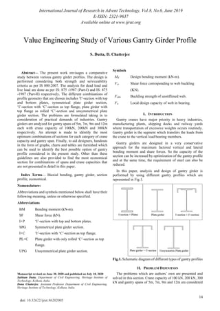
In this paper, analysis and design of gantry girder is
performed by using different gantry profiles which are
represented in Fig.1.
Fig.1. Schematic diagram of different types of gantry profiles
II. PROBLEM DEFINITION
The problems which are authors’ own are presented and
solved in this section. Crane capacity of 100 kN, 200 kN, 300
kN and gantry spans of 5m, 7m, 9m and 12m are considered
Value Engineering Study of Various Gantry Girder Profile
S. Dutta, D. Chatterjee
2. International Journal of Research in Advent Technology, Vol.8, No.6, June 2019
E-ISSN: 2321-9637
Available online at www.ijrat.org
15
doi: 10.32622/ijrat.86202005
for this study. The various other specifications that are taken
as constant for all the cases are mentioned in Table I.
Table I: Design parameters
Self-weight of crane girder excluding
trolley
200 kN
Self-weight of trolley, electric motor,
hook etc.
50 kN
Minimum hook approach 1.2m
Wheel base distance 3.5m
Span of crane girder 20m
Self-weight of rail section 0.3 kN/m
Self-weight of gantry girder section 1.6 kN/m
Diameter of crane wheel 150mm
Grade of steel used E250
Design procedure:
Step1: Calculation of maximum wheel load
• For calculating maximum wheel load the hook of the
trolley should be at a distance of minimum hook approach
from the end of the crane girder.
• Due to impact loading 25% extra load should be
considered (as per IS 875(2):1987 clause 6.3) [7].
• A load factor of 1.5 should be multiplied with the obtained
value [6].
Step2: Calculation of surge load
• Total lateral surge load should be considered as 10% of the
crane load plus trolley load.
• A load factor of 1.5 should be multiplied with the obtained
value.
Step3: Calculation of longitudinal breaking load
• Longitudinal breaking load should be calculated as 5% of
the static wheel load.
• A load factor of 1.5 should be multiplied with the obtained
value.
Step4: Calculation of bending moment
• Bending moment due to wheel load should be calculated
using absolute maximum bending moment theorem.
• Bending moment produced by self-weight of gantry girder
and rail section and bending moment due to longitudinal
breaking load should be considered.
• Summation of all these bending moments is the total
bending moment generated in the gantry girder. A load factor
of 1.5 should be multiplied with the obtained bending
moment to find out the factored bending moment.
• Bending moment due to lateral surge load should take into
consideration which acts in the horizontal direction.
Step5: Calculation of shear force
• Maximum shear force due to wheel load can be obtained
when one set of crane wheel is placed just at the support.
• Shear force due to self-weight of gantry girder and rail
section and reaction due to drag should be considered.
• Summation of these entire shear forces is the total shear
force generated in the gantry girder. A load factor of 1.5
should be multiplied with the obtained shear force to find out
the factored shear force.
Step6: Assumption of section
• The assumed depth of the gantry girder section should be
within the economic depth and the shear depth.
• Area of flanges should be calculated from the bending
moment criteria. As the gantry girder has to withstand
bi-axial bending so the assumed area of flanges should be
increased by 30-40%.
Step7: Check for bending moment capacity of the section
• Vertical and lateral bending moment capacities of the
provided section should be calculated as per IS 800:2007
clause 8.2.2. [5].
• If the interaction ratio for bi-axial bending is less than one
then the section is safe against bending.
Step8: Check for share force capacity of the section
• Shear force corresponding to web buckling Vcr is
calculated as per clause 8.4.2.2 of IS 800:2007 [5].
• If the calculated share force capacity of the section is
greater than the factored share force then the section is safe
against share.
Step9: Check for web buckling
• Buckling strength of unstiffened web Fcdw can be
calculated as per clause 8.7.3.1 of IS 800:2007 [1] [5].
Step10: Check for web crippling
• Local design capacity of web in bearing Fw can be
calculated as per clause 8.7.4 of IS 800:2007 [5].
Step11: Check for deflection
• Lateral and horizontal deflection of gantry girder under
service loads should be less than (gantry span/750) in mm [4].
III. RESULTS AND DISCUSSION
The generated factored vertical bending moments (MZZ),
lateral bending moments (MYY) and factored shear forces
(SF) of different gantry spans are tabulated in Table 2. These
entities are load dependent entities and remain constant for all
types of gantry profiles.
Table II: Developed bending moments and shear forces for
different combinations of gantry span and crane capacities
Gantry
span
Crane
capacity
MZZ
(kN-m)
MYY
(kN-m)
SF
(kN)
5 m
100 kN 249.76 5.94 302.2
200 kN 343.7 9.9 417.29
300 kN 437.64 13.86 532.38
7 m
100 kN 464.81 11.07 349.85
200 kN 639.3 18.46 482.42
300 kN 813.79 25.84 614.98
3. International Journal of Research in Advent Technology, Vol.8, No.6, June 2019
E-ISSN: 2321-9637
Available online at www.ijrat.org
16
doi: 10.32622/ijrat.86202005
9 m
100 kN 691.36 16.43 377.59
200 kN 949.76 27.38 519.86
300 kN 1208.2 38.33 662.14
12 m
100 kN 1043.26 24.62 403.64
200 kN 1430.17 41.04 554.41
300 kN 1817.07 57.46 705.18
The section properties of the various combinations of profile
sections and bending moment and shear force capacities are
tabulated in Table 3 to Table 5. Sections properties which
include vertical bending moment capacity (MZZ), lateral
bending moment capacity (MYY), shear force capacity (SF),
cross sectional area (C/S) and weight per meter length of the
given sections are tabulated for different gantry spans and
gantry profiles. Fig 2 to Fig 4 shows the graphical
representation of weight of steel required per meter length
different gantry profiles.
Table III: Sectional properties and load carrying capacities of different profile geometry for crane capacity of 100KN
Gantry
profile
Gantry
span
(m)
MZZ
(kN-m)
MYY
(kN-m)
SF
(kN)
C/S
Area
(mm2
)
Weight
of steel
(kg/m)
Remarks
5 346.15 26.18 555.04 12027 94.41
Easy to design the
section but not
economical for higher
gantry spans like 9m
and 12m.
7 650.96 53.18 944.75 19121 150.1
9 862.67 94.64 881.77 23038 180.85
12 1305 146 929 31686 286.74
5 313.88 32.18 602.76 10476 82.24 Easy to design but
symmetric sections
are not optimized for
biaxial bending.
7 559.12 64.1 922.33 16470 129.3
9 817.86 105.55 1055.1 21610 169.64
12 1228 181.9 1472 30200 237.07
5 335.14 53.45 555 11665 91.57
Optimized geometry
for biaxial bending.
But rolled I and C
sections are not
available for higher
gantry spans.
7 537.51 92.18 808.3 16512 129.62
9 785.95 181.1 944.8 20987 164.75
12
Not
possible
Not
possible
Not
possible
Not
possible
Not
possible
5 304.94 65.45 866 10301 80.86
Very optimized
geometry for biaxial
bending but for higher
gantry spans,
available rolled
‘C’-sections is not
proper.
7 502.72 156 938.2 13616 106.89
9 753.85 205.64 1154.7 17443 136.93
12 1219.4 205.64 1558.8 28343 222.49
5 278.31 61.36 794 10400 81.64
Very optimized
geometry for biaxial
bending. As no rolled
sections are used so
for bigger spans it is
highly customizable.
7 530.57 163.4 938.2 15070 118.3
9 766.46 258.55 1118.6 19350 151.9
12 1112.9 412.9 1559 26120 205
From Table 3 clearly indicates for low crane capacity like
100 kN and for gantry spans 5m, 7m and 9m the most
economic gantry profile is “Plate girder with only rolled
‘C’-section as top flange” but for gantry span of 12 m
“Unsymmetrical plate girder section” is the most economic
profile.
4. International Journal of Research in Advent Technology, Vol.8, No.6, June 2019
E-ISSN: 2321-9637
Available online at www.ijrat.org
17
doi: 10.32622/ijrat.86202005
Table IV: Sectional properties and load carrying capacities of different profile geometry for crane capacity of 200KN
Gantry
profile
Gantry
span
(m)
MZZ
(kN-m)
MYY
(kN-m)
SF
(kN)
C/S
Area
(mm2
)
Weight
of steel
(kg/m)
Remarks
5 518.96 40.36 669.2 14784 116.76
For higher gantry
spans like 9m, 12m
and for higher crane
capacity this profile is
very uneconomic.
7 885.37 70.64 944.75 21861 171.61
9 1251.78 124.1 929 28566 224.24
12 2040.6 236.5 929 40986 321.74
5 475.3 45.55 819.85 13680 107.4
Easy to design but
symmetric sections are
not optimized for
biaxial bending.
7 799.94 86.45 1030.6 18840 147.89
9 1492.83 160.1 1163.4 25660 201.43
12 1887.7 257.7 1635.1 36528 286.7
5 488.75 85.64 669.2 14375 112.84
Because of depth
limitations of rolled
‘I’-section this profile
is not possible for
higher gantry spans
like 9m and 12 m.
7 798.92 144.82 944.7 20185 158.45
9
Not
possible
Not
possible
Not
possible
Not
possible
Not
possible
12
Not
possible
Not
possible
Not
possible
Not
possible
Not
possible
5 410.69 115.64 866.04 11564 90.78
Very optimized
geometry for biaxial
bending but for higher
gantry spans and crane
capacity available
rolled ‘C’-section is
not proper.
7 694.87 205.64 1082.5 15543 122
9 1076.93 205.64 1515.6 22643 177.75
12 1821.43 205.64 1732 34739 272.7
5 402.35 84.27 902.12 12100 94.98
Most economical
profile for higher
gantry spans and crane
capacities. As no
rolled sections are
used it is easily
customizable.
7 705.93 214.91 1082.5 17320 135.96
9 1091.78 329.18 1472.3 23520 184.6
12 1583 545.7 1732 30300 237.8
From Table 4 clearly indicates for medium crane capacity
like 200 kN and for gantry spans 5m, 7m and 9m the most
economic gantry profile is “Plate girder with only rolled
‘C’-section as top flange” but for gantry span 12m
“Unsymmetrical plate girder section” is the most economic
profile.
Table V: Sectional properties and load carrying capacities of different profile geometry for crane capacity of 300KN
Gantry
Profile
Gantry
Span
(m)
MZZ
(kN-m)
MYY
(kN-m)
SF
(kN)
C/A
Area
(mm2
)
Weight
of steel
(kg/m)
Remarks
5 649.15 48 808.29 17011 133.54
Depth limitation of
rolled ‘I’-section make
this profile
uneconomical for
higher gantry spans
and crane capacities.
7 1103.38 99.55 881.71 24238 190.26
9 1678.5 170.45 929 33886 266
12 2748.6 359.5 929 49986 392.4
5. International Journal of Research in Advent Technology, Vol.8, No.6, June 2019
E-ISSN: 2321-9637
Available online at www.ijrat.org
18
doi: 10.32622/ijrat.86202005
5 598.02 55.09 892 14980 117.6
Easy to design but
symmetric sections are
not optimized for
biaxial bending.
7 1089.1 111.27 1316.4 23120 181.5
9 1611.74 181.91 1515.6 30500 239.42
12 2268.4 287.2 2059.2 40866 320.8
5 622.55 92.18 808.3 16512 129.6
Because of depth
limitations of rolled
‘I’-section this profile
is not possible for
higher gantry spans
like 9m and 12m.
7 973.34 171.55 929 23050 180.94
9
Not
possible
Not
possible
Not
possible
Not
possible
Not
possible
12
Not
possible
Not
possible
Not
possible
Not
possible
Not
possible
5 505.6 115.64 974.3 12564 98.63
Very optimized
geometry for biaxial
bending but for higher
gantry spans like 12m
rolled ‘C’-section is
not available.
7 939.9 205.64 1429 18993 149.1
9 1477.1 205.64 1602.2 27393 215
12
Not
possible
Not
possible
Not
possible
Not
possible
Not
possible
5 519.41 120.8 938.21 13150 103.23
Most economical
profile for higher
gantry spans and crane
capacities. As no
rolled sections are
used it is easily
customizable.
7 928.54 240.5 1428.9 19620 154
9 1368.6 385.36 1645.5 25620 201.2
12 2033.8 660.3 2172 35650 279.85
From Table 5 clearly indicates for high crane capacity like
300 kN and for gantry spans 5m and 7m the most economic
gantry profile is “Plate girder with only rolled ‘C’-section as
top flange” but for gantry span 9m and 12m “Unsymmetrical
plate girder section” is the most economic profile.
Fig.2. Steel requirements of different gantry profiles for crane capacity 100 kN
6. International Journal of Research in Advent Technology, Vol.8, No.6, June 2019
E-ISSN: 2321-9637
Available online at www.ijrat.org
19
doi: 10.32622/ijrat.86202005
Fig.3. Steel requirement of different gantry profiles for crane capacity 200 kN
Fig.4. Steel requirement of different gantry profiles for crane capacity 400 kN
*The blank bar represents that the gantry profile is not possible for
that particular gantry span because of the unavailability of the rolled
section.
Figure 4-6 depicts the weight of steel required per meter
length of gantry girders of various gantry profiles for crane
capacities of 100kN, 200kN and 300kN respectively. The
percentage of extra steel required for different gantry profiles
with respect to the most economic gantry profile for a
particular gantry span are also indicated.
7. International Journal of Research in Advent Technology, Vol.8, No.6, June 2019
E-ISSN: 2321-9637
Available online at www.ijrat.org
20
doi: 10.32622/ijrat.86202005
IV. DESIGN METHODOLOGY
The design is initiated with a very basic symmetrical sections
like “rolled I-section with top and bottom plates” and
“symmetrical plate girder section” [2] [3]. But the problem
with the first gantry profile is the depth of the rolled section is
limited so for higher gantry spans and crane capacities the
available profile becomes very uneconomical.
For gantry girders as the horizontal surge load is transferred
at the top flange level (specifically at the contact point of
crane wheel and gantry rail) so using unsymmetrical section
with bigger compression flange is found to be more
economical. So in the subsequent trial the gantry profiles are
considered as “rolled I-section with rolled C-section as top
flange” and “web and bottom flange as plate section with top
flange as rolled C-section”. As a result the sections are found
to be very economical but the problem is the rolled sections
are not available for the higher gantry spans and crane
capacities.
To eliminate this problem in the third and final trial keeping
the same geometry as per second trial the whole gantry
profile is designed as plate girder section with bigger
compression flange as C-section. This results into the most
economic section for gantry span of 9m and 12m.
V. CONCLUSIONS
• Load calculations for gantry girders are done in a
very conservative way so by optimizing the gantry
girder profile economy can be achieved.
• Gantry girders are such kind of steel beams where
vertical and lateral bending moments can come at a
same time. So the designed sections need to be safe
against bi-axial bending.
• For gantry girders horizontal loads are released at
the top flange level so unsymmetrical sections (with
a bigger compression flange) will be more
economical than symmetrical sections.
CONFLICT OF INTEREST
On behalf of all authors, the corresponding author states that
there is no conflict of interest.
REFERENCES
[1] Alandkar,P.M. and Limaye,A. 2013. Strength of Welded Plate Girder
with Corrugated Web Plate. Journal of Engineering Research and
Applications, 3(5): 1925-1930.
[2] Garg,A. 2016. Gantry girders in India. International Journal of Civil,
Mechanical and Energy Science, 2(6): 15-19.
[3] Iyappan,S. Kumar,P.V. Sarathy,R.V. Tamilvanan,G. Venkatesh,A. and
Vignesh,S. 2016. Design of an overhead plate gantry
girder.International Journal of Development Research, 6(5):
7821-7823.
[4] Subramanian,N. 2010. Steel Structures Design and Practice, Oxford
University Press, New Delhi.
[5] IS 800:2007, Code of practice for general construction in steel, Bureau
of Indian Standards, New Delhi.
[6] IS 875(part I):2003, Code of practice for design loads (other than
earthquake) for buildings and structures, Bureau of Indian Standards,
New Delhi.
[7] IS 875(part II):2010, Code of practice for design loads (other than
earthquake) for buildings and structures, Bureau of Indian Standards,
New Delhi.
AUTHORS PROFILE
Subham Dutta is pursuing his B.Tech degree in Civil
Engineering from Heritage Institute of Technology,
Kolkata.
Dona Chatterjee received B.E. and M.E. degrees in
Civil Engineering and Structural Engineering from
Jadavpur University, Kolkata in the year 2010 and
2015, respectively. Author has 3 years of industrial
experience and 6 years of academic and research
experience mainly in areas of structural engineering.
![International Journal of Research in Advent Technology, Vol.8, No.6, June 2019
E-ISSN: 2321-9637
Available online at www.ijrat.org
15
doi: 10.32622/ijrat.86202005
for this study. The various other specifications that are taken
as constant for all the cases are mentioned in Table I.
Table I: Design parameters
Self-weight of crane girder excluding
trolley
200 kN
Self-weight of trolley, electric motor,
hook etc.
50 kN
Minimum hook approach 1.2m
Wheel base distance 3.5m
Span of crane girder 20m
Self-weight of rail section 0.3 kN/m
Self-weight of gantry girder section 1.6 kN/m
Diameter of crane wheel 150mm
Grade of steel used E250
Design procedure:
Step1: Calculation of maximum wheel load
• For calculating maximum wheel load the hook of the
trolley should be at a distance of minimum hook approach
from the end of the crane girder.
• Due to impact loading 25% extra load should be
considered (as per IS 875(2):1987 clause 6.3) [7].
• A load factor of 1.5 should be multiplied with the obtained
value [6].
Step2: Calculation of surge load
• Total lateral surge load should be considered as 10% of the
crane load plus trolley load.
• A load factor of 1.5 should be multiplied with the obtained
value.
Step3: Calculation of longitudinal breaking load
• Longitudinal breaking load should be calculated as 5% of
the static wheel load.
• A load factor of 1.5 should be multiplied with the obtained
value.
Step4: Calculation of bending moment
• Bending moment due to wheel load should be calculated
using absolute maximum bending moment theorem.
• Bending moment produced by self-weight of gantry girder
and rail section and bending moment due to longitudinal
breaking load should be considered.
• Summation of all these bending moments is the total
bending moment generated in the gantry girder. A load factor
of 1.5 should be multiplied with the obtained bending
moment to find out the factored bending moment.
• Bending moment due to lateral surge load should take into
consideration which acts in the horizontal direction.
Step5: Calculation of shear force
• Maximum shear force due to wheel load can be obtained
when one set of crane wheel is placed just at the support.
• Shear force due to self-weight of gantry girder and rail
section and reaction due to drag should be considered.
• Summation of these entire shear forces is the total shear
force generated in the gantry girder. A load factor of 1.5
should be multiplied with the obtained shear force to find out
the factored shear force.
Step6: Assumption of section
• The assumed depth of the gantry girder section should be
within the economic depth and the shear depth.
• Area of flanges should be calculated from the bending
moment criteria. As the gantry girder has to withstand
bi-axial bending so the assumed area of flanges should be
increased by 30-40%.
Step7: Check for bending moment capacity of the section
• Vertical and lateral bending moment capacities of the
provided section should be calculated as per IS 800:2007
clause 8.2.2. [5].
• If the interaction ratio for bi-axial bending is less than one
then the section is safe against bending.
Step8: Check for share force capacity of the section
• Shear force corresponding to web buckling Vcr is
calculated as per clause 8.4.2.2 of IS 800:2007 [5].
• If the calculated share force capacity of the section is
greater than the factored share force then the section is safe
against share.
Step9: Check for web buckling
• Buckling strength of unstiffened web Fcdw can be
calculated as per clause 8.7.3.1 of IS 800:2007 [1] [5].
Step10: Check for web crippling
• Local design capacity of web in bearing Fw can be
calculated as per clause 8.7.4 of IS 800:2007 [5].
Step11: Check for deflection
• Lateral and horizontal deflection of gantry girder under
service loads should be less than (gantry span/750) in mm [4].
III. RESULTS AND DISCUSSION
The generated factored vertical bending moments (MZZ),
lateral bending moments (MYY) and factored shear forces
(SF) of different gantry spans are tabulated in Table 2. These
entities are load dependent entities and remain constant for all
types of gantry profiles.
Table II: Developed bending moments and shear forces for
different combinations of gantry span and crane capacities
Gantry
span
Crane
capacity
MZZ
(kN-m)
MYY
(kN-m)
SF
(kN)
5 m
100 kN 249.76 5.94 302.2
200 kN 343.7 9.9 417.29
300 kN 437.64 13.86 532.38
7 m
100 kN 464.81 11.07 349.85
200 kN 639.3 18.46 482.42
300 kN 813.79 25.84 614.98](data:image/gif;base64,R0lGODlhAQABAIAAAAAAAP///yH5BAEAAAAALAAAAAABAAEAAAIBRAA7)