1. IOSR Journal of Mechanical and Civil Engineering (IOSR-JMCE)
e-ISSN: 2278-1684,p-ISSN: 2320-334X, Volume 13, Issue 2 Ver. II (Mar. - Apr. 2016), PP 26-28
www.iosrjournals.org
DOI: 10.9790/1684-1302022628 www.iosrjournals.org 26 | Page
Design And Fabrication Of Downdraft Gasifier Applied To I.C.
Engine
1
kunal Bankhile, 2
chirag Basrur, 3
anvay Churi, 4
yash Kawediya
1,2,3,4
Mechanical Engineering Department, V.C.E.T Vasai.
Abstract: Today’s Energy Hungry World is consuming non-renewable sources of energy such as fossil fuels at
alarming rates, which has increased the importance of developing renewable energy sources. Biomass is one
such source of renewable energy which is abundantly available in India in the form of industrial and
agricultural by-products. In this project we aim to contribute in a small way to this changing face of sustainable
energy resources by designing and fabricating a downdraft gasifier using two sources of biomass viz. rice husk
and wood pellets. The syn-gas subsequently produced would be used to run an I.C. Engine and a performance
analysis would be conducted.
I. Introduction
Biomass gasification is basically the conversion of solid biofuels into a combustible gas mixture known
as „syn-gas‟ or „producer gas.‟ A gasifier is a chemical reactor that performs this conversion
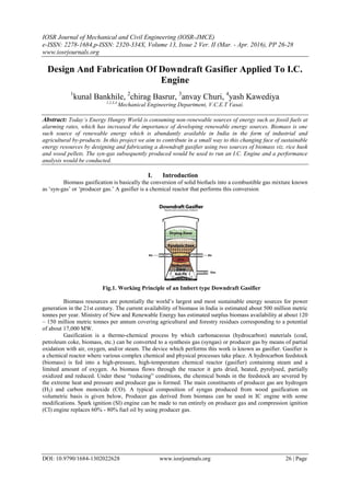
Fig.1. Working Principle of an Imbert type Downdraft Gasifier
Biomass resources are potentially the world‟s largest and most sustainable energy sources for power
generation in the 21st century. The current availability of biomass in India is estimated about 500 million metric
tonnes per year. Ministry of New and Renewable Energy has estimated surplus biomass availability at about 120
– 150 million metric tonnes per annum covering agricultural and forestry residues corresponding to a potential
of about 17,000 MW.
Gasification is a thermo-chemical process by which carbonaceous (hydrocarbon) materials (coal,
petroleum coke, biomass, etc.) can be converted to a synthesis gas (syngas) or producer gas by means of partial
oxidation with air, oxygen, and/or steam. The device which performs this work is known as gasifier. Gasifier is
a chemical reactor where various complex chemical and physical processes take place. A hydrocarbon feedstock
(biomass) is fed into a high-pressure, high-temperature chemical reactor (gasifier) containing steam and a
limited amount of oxygen. As biomass flows through the reactor it gets dried, heated, pyrolysed, partially
oxidized and reduced. Under these “reducing” conditions, the chemical bonds in the feedstock are severed by
the extreme heat and pressure and producer gas is formed. The main constituents of producer gas are hydrogen
(H2) and carbon monoxide (CO). A typical composition of syngas produced from wood gasification on
volumetric basis is given below, Producer gas derived from biomass can be used in IC engine with some
modifications. Spark ignition (SI) engine can be made to run entirely on producer gas and compression ignition
(CI) engine replaces 60% - 80% fuel oil by using producer gas.
2. Design And Fabrication Of Downdraft Gasifier Applied To I.C. Engine
DOI: 10.9790/1684-1302022628 www.iosrjournals.org 27 | Page
II. Experimental Details
2.1. Design Procedure
The first step was to select an engine. Considering the budget of our project we select an genset having
an output of 4KW. The next steps involved some calculations of stroke volume and gas output that the gasifier
would have to produce considering an air gas ratio of 1.1:1.
The crucial part involved the selection of the Hearth Load. An important factor in the sizing of any
gasifier is the superficial velocity of the gas when it passes through the narrowest part of the gasification zone. It
actually represents the specific gas production rate i.e. gas volume per unit cross sectional area per unit time. A
closely related term is the maximum hearth load which is expressed as gas volume/hearth area-hour. This term
enables one to compare the performance of a wide range of gasifiers on a common basis.
For an Imbert Downdraft Gasifier the maximum Hearth Load is 0.9 m3
/cm2
-h, which is has been
determined by experimental tests. Using this term, we calculated the throat diameter. Subsequently a standard
set of dimensions was chosen from the following standard table from the SERI Handbook.
Subsequently, the biomass consumption rate was calculated with certain assumptions.
2.1. Final Design
The initial design was presented to the fabricator. He suggested certain improvements in the design
which were implemented and the gasifier was redesigned. A sectional view of the design of the throat section is
shown below.
The other components include a hopper section, ash section and flanges.
2.3. Material Procurement and Fabrication
Once the design was finalised, we had to determine the amount of material that would be required for
the various components. Stainless steel was chosen as it can sustain the high temperatures of up to 1200o
C
3. Design And Fabrication Of Downdraft Gasifier Applied To I.C. Engine
DOI: 10.9790/1684-1302022628 www.iosrjournals.org 28 | Page
which would be attained at the throat section. Initially we procured suitable scrap materials in order to reduce
the cost and the remaining materials where ordered from a vendor. Once all the required
materials were procured the fabrication was started. It took approximately 2 weeks for the fabrication to
complete. The only problem faced was in procurement of pipes, as pipes of the required diameter were not
available, they had to be machined on a lathe machine. The wood
pellets having moisture content less than 14% were then subsequently procured.
2.4. Experimentation and Analysis
Once the complete assembly of the gasifier is finished, it would be operated using wood pellets as
biomass and charcoal grate for initial starting. The gas generated would be tested to determine its composition,
calorific value and most importantly tar content. A
photograph of the fabricated gasifier is shown below.
III. Results And Discussion
From the above description, we can conclude that such a downdraft gasifier will be applicable to many
small scale industries. Especially the industries which produce large quantities of biomass byproducts would
largely benenift from the implementation of such a gasifier based system, which would see a drastic fall in the
fuel requirements and in turn would increase profits.
An added advantage of downdraft gasifiers over other types is that the gas produced has minimal tar
content which enables the gas to be used in a I.C. Engine with minimal or no prior conditioning.
IV. Conclusions
1. Drastic reduction in fuel consumption.
2. Low Tar content.
3. Easily implemented in small scale industries, which would cause saving of non-renewable energy resources
and provide an alternate sustainable energy source.
Acknowledgments
The team members pay sincere gratitude to Prof. Dipak Choudhari, Head of Department, Civil
Engineering V.C.E.T, Vasai for guiding us on the topic and encouraging us to participate in the paper
presentation event. We thank him for sharing his vital inputs on the topic and developing an interest to learn and
understand new technologies introduced in the field we are studying.
References
[1]. Handbook of Biomass Downdraft Gasifier Engine Systems a Solar Technical Information Program by U.S. Department of Energy.
[2]. Wood Gas as Engine Fuel – Food and Agriculture Organization of the United Nations.
[3]. International Journal of Mechanical Engineering-Paper on Design and Development of Downdraft Gasifier- Paper No – ISSN 2319-
2240.
[4]. A thesis on Design and Development of downdraft Gasifier for operating C.I. Engine on dual fuel mode- National Institute of
Technology Rourkela.