
Recommandé
Contenu connexe
Tendances
Tendances (20)
Similaire à Smith Catalog
Similaire à Smith Catalog (20)
Plus de Ir. Hadi Budiman
Smith Catalog
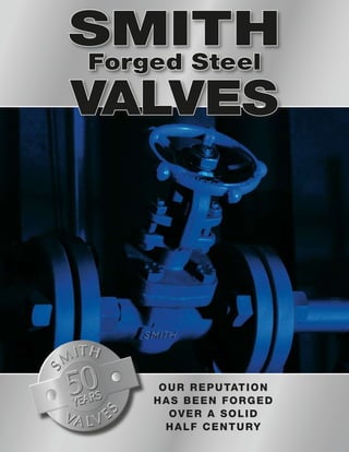
- 1. Our Reputation Has Been Forged Over A Solid Half Century SMITH Forged Steel Valves
- 2. In the Beginning When he founded his company in the mid 1950s, James Dewolf Smith focused on the production of forged gate, globe and check valves for use primarily in the petrochemical industry. Ten years later he added a forged brass ball valve line to the production stream. By the mid 1970s, Smith was one of the industry’s largest producers of industrial gate, globe, check, and ball valves under the 2.5" size. The oil business was booming and producers were ordering valves at a remarkable rate. The End of an Era By now Tony Smith had taken over his father’s business, added exotic stainless and alloy items to the product offerings, and relocated to a brand new production facility. Then U.S. oil production came to a virtual halt. A dramatic downturn in market conditions and increased competition forced Tony to make substantial changes, laying off workers and moving most production offshore. He began producing private label valves and licensed his industrial ball valves to raise cash. Eventually the economy forced Tony to sell to Cornerstone Financial and a chain of corporate owners ensued. Finally Smith’s production facilities were moved to Longview, Texas. But the company continued to falter. New Beginnings With the turn of the century came new life for Smith. In March of 2000, the Newdell Company bought Smith’s assets and moved production to Italy. The downward trend was reversed and sales began to climb. In the fall of 2006, production was returned to the USA, this time to Houston, Texas where the owners had just completed a new manufacturing and warehousing facility. Smith is now producing valves at a rate of 20,000 per month and is growing rapidly. Throughout the company history, one thing has never changed with the Smith brand: product quality. Yes, the Newdell Company has made substantial investments in technology resulting in improved engineering and manufacturing practices. Yet the time-tested Smith designs and the unique color-coding system remain essentially unchanged. You see, the Smith brand has a reputation to uphold. A reputation for quality that has been forged over a solid half-century. A reputation that will only be enhanced as we move into our second half-century of production. 1956 80’s 2001
- 3. Coding Information.........................................................................................................2, 3 G A T E V A L V E S Class 800 Conventional Port........................................0800/0870.................................................5 Full Port.......................................................0888/5870.................................................6 Inside Screw, Conventional Port.................0850/0890.................................................7 Conventional Port, Butt Weld......................0800B........................................................9 Integrally Reinforced Extended Body..........0874/0875...............................................15 Extended Body............................................0811-0814/0876-0879............................16 Class 1500 Conventional Port........................................1500/1570.................................................8 Conventional Port, Butt Weld........................1500B........................................................9 Full Port........................................................1588/1578................................................10 Class 2500 Full Port........................................................2578........................................................11 Class 150, 300, 600, 1500 Conventional Port, Flanged...........................0815/0830/0860.......................................12 Full Port, Flanged.........................................5815/5830................................................13 Full Port, Flanged, Butt Weld........................0895/0895B..............................................14 G L O B E V A L V E S Class 800 Throttle Valve...............................................0G80/0G87..............................................18 Flow Control.................................................FG80........................................................22 Class 1500 Throttle Valve...............................................G150/G157..............................................19 Class 150, 300, 600, 1500 Flanged........................................................0G81/0G83/0G86/G895......................20, 21 Class 1690/2690 Y-Pattern, Non-rotating Stem.......................Y162-Y262..............................................35 Y-Pattern, Rotating Stem..............................Y167-Y267...............................................36 C H E C K V A L V E S Class 800 Ball...............................................................0B80/SB80..............................................24 Piston...........................................................0C80/SC80.............................................25 Swing...........................................................SW80......................................................25 Y-Pattern, Ball/Piston....................................YB80/YC80.............................................27 Class 1500 Ball...............................................................B150/SB15..............................................26 Piston...........................................................C150/SC15.............................................26 Class 150, 300, 600 Flanged, Piston.............................................0C81/SC81, 0C83/SC83, 0C86/SC86.......................................28, 29 Flanged, Ball.................................................0B81/SB81, 0B83/SB83, 0B86/SB86........................................30, 31 S P E C I AL I T Y V A L V E S.........................................................................32, 33 Class 1690/2690 Y-Pattern......................................................YC16/YC26.............................................37 C R Y O G E N I C V A L V E S............................................................................38-42 B e l l o w s S e a l .......................................................................................... 43 T E C H N I C AL ..................................................................................................44-47 Index
- 5. END CAPS GATE GLOBE VALVES Handwheels Powder coat Handwheel color indicates Body-Bonnet Material or Special Packing BLUE ASTM A105 Carbon Steel ORANGE ASTM A350 LF2 Low Temp. PURPLE MONEL WHITE ASTM 182 F5 5 Cr, 1 /2 Mo GREEN ASTM 182 F9 9 Cr, 1 Mo RED Teflon Packing Gaskets or Seals 500°F/250°C Max Temp. PINK F20 (ALLOY 20) BROWN ASTM A182 F22 21 /2 Cr, 1 Mo Name Plates are Stainless Steel Nameplate color indicates Trim Material (Gate, Globe and Check) Unique Color Coding SILVER ASTM A182 F316 ASTM A182 F316L 316 S.S. YELLOW ASTM A182 F11 11 /4 Cr, 1 /2 Mo
- 6. Gate Valves
- 7. CLASS 800 CONVENTIONAL PORT BOLTED BONNET GATE VALVE - THREADED or SOCKET WELD - INCHES (MM) VALVE SIZE NPS (DIN) END TO END CENTER TO TOP (OPEN) HANDWHEEL DIAMETER PORT DIAMETER SOCKET DEPTH SOCKET DIAMETER NPT THRD APPROX. WEIGHT LBS (KG) 1/4 (8) 3.25 (83) 6.31 (160) 4.00 (102) 0.31 (8) 0.39 (10) 0.56 (14) 1/4-18 3.8 (1.7) 3/8 (10) 3.25 (83) 6.31 (160) 4.00 (102) 0.39 (10) 0.39 (10) 0.69 (18) 3/8-18 3.8 (1.7) 1/2 (15) 3.25 (83) 6.31 (160) 4.00 (102) 0.39 (10) 0.39 (10) 0.86 (22) 1/2-14 3.8 (1.7) 3/4 (20) 3.50 (89) 6.50 (165) 4.00 (102) 0.50 (13) 0.51 (13) 1.07 (27) 3/4-14 4.5 (2.0) 1 (25) 3.88 (98) 7.25 (184) 4.00 (102) 0.75 (19) 0.51 (13) 1.34 (34) 1-11 1/2 6.3 (2.8) 1 1/4 (32) 4.75 (121) 9.13 (232) 5.50 (140) 1.19 (30) 0.51 (13) 1.68 (43) 1 1/4-11 1/2 9.5 (4.3) 1 1/2 (40) 4.75 (121) 9.13 (232) 5.50 (140) 1.19 (30) 0.51 (13) 1.92 (49) 1 1/2-11 1/2 12.0 (5.4) 2 (50) 5.50 (140) 11.06 (281) 6.63 (168) 1.50 (38) 0.63 (16) 2.41 (61) 2-11 1/2 20.5 (9.3) 0800-0870 Gate Valves Forged Steel OSY—Conventional Port Valves comply with applicable portions of API 602 and ASME B16.34 CLASS 800 CONVENTIONAL PORT WELDED BONNET GATE VALVE - THREADED or SOCKET WELD - INCHES (MM) VALVE SIZE NPS (DIN) END TO END CENTER TO TOP (OPEN) HANDWHEEL DIAMETER PORT DIAMETER SOCKET DEPTH SOCKET DIAMETER NPT THRD APPROX. WEIGHT LBS (KG) 1/4 (8) 3.25 (83) 6.19 (157) 4.00 (102) 0.31 (8) 0.39 (10) 0.56 (14) 1/4-18 3.3 (1.5) 3/8 (10) 3.25 (83) 6.25 (159) 4.00 (102) 0.39 (10) 0.39 (10) 0.69 (18) 3/8-18 3.3 (1.5) 1/2 (15) 3.25 (83) 6.25 (159) 4.00 (102) 0.39 (10) 0.39 (10) 0.86 (22) 1/2-14 3.3 (1.5) 3/4 (20) 3.50 (89) 6.50 (165) 4.00 (102) 0.50 (13) 0.51 (13) 1.07 (27) 3/4-14 3.8 (1.7) 1 (25) 3.88 (98) 7.25 (184) 4.00 (102) 0.75 (19) 0.51 (13) 1.34 (34) 1-11 1/2 5.3 (2.4) 1 1/4 (32) 4.75 (121) 9.13 (232) 5.50 (140) 1.19 (30) 0.51 (13) 1.68 (43) 1 1/4-11 1/2 10.3 (4.6) 1 1/2 (40) 4.75 (121) 9.13 (232) 5.50 (140) 1.19 (30) 0.51 (13) 1.92 (49) 1 1/2-11 1/2 9.8 (4.4) 2 (50) 5.50 (140) 11.00 (279) 6.63 (168) 1.50 (38) 0.63 (16) 2.41 (61) 2-11 1/2 16.0 (7.3) 08700800 Class 800 1/4 - 2
- 8. CLASS 800 FULL PORT BOLTED BONNET GATE VALVE - THREADED or SOCKET WELD - INCHES (MM) VALVE SIZE NPS (DIN) END TO END CENTER TO TOP (OPEN) HANDWHEEL DIAMETER PORT DIAMETER SOCKET DEPTH SOCKET DIAMETER NPT THRD APPROX. WEIGHT LBS (KG) 1/4 (8) 3.25 (83) 6.25 (159) 4.00 (102) 0.31 (8) 0.39 (10) 0.56 (14) 1/4-18 3.8 (1.7) 3/8 (10) 3.25 (83) 6.31 (160) 4.00 (102) 0.39 (10) 0.39 (10) 0.69 (18) 3/8-18 3.8 (1.7) 1/2 (15) 3.50 (89) 6.50 (165) 4.00 (102) 0.50 (13) 0.39 (10) 0.86 (22) 1/2-14 4.8 (2.2) 3/4 (20) 3.88 (98) 7.25 (184) 4.00 (102) 0.75 (19) 0.51 (13) 1.07 (27) 3/4-14 6.3 (2.8) 1 (25) 4.75 (121) 9.13 (232) 4.00 (102) 0.94 (24) 0.51 (13) 1.34 (34) 1-11 1/2 9.8 (4.4) 1 1/4 (32) 4.75 (121) 9.13 (232) 5.50 (140) 1.19 (30) 0.51 (13) 1.68 (43) 1 1/4-11 1/2 11.5 (5.2) 1 1/2 (40) 5.50 (140) 11.06 (281) 6.63 (168) 1.50 (38) 0.51 (13) 1.92 (49) 1 1/2-11 1/2 21.8 (9.9) 2 (50) 5.69 (144) 12.38 (314) 6.63 (168) 2.00 (51) 0.51 (13) 1.92 (49) 1 1/2-11 1/2 24.0 (10.9) CLASS 800 FULL PORT WELDED BONNET GATE VALVE - THREADED or SOCKET WELD - INCHES (MM) VALVE SIZE NPS (DIN) END TO END CENTER TO TOP (OPEN) HANDWHEEL DIAMETER PORT DIAMETER SOCKET DEPTH SOCKET DIAMETER NPT THRD APPROX. WEIGHT LBS (KG) 1/4 (8) 3.25 (83) 6.25 (159) 4.00 (102) 0.31 (8) 0.39 (10) 0.56 (14) 1/4-18 3.3 (1.5) 3/8 (10) 3.25 (83) 6.25 (159) 4.00 (102) 0.39 (10) 0.39 (10) 0.69 (18) 3/8-18 3.3 (1.5) 1/2 (15) 3.50 (89) 6.50 (165) 4.00 (102) 0.50 (13) 0.39 (10) 0.86 (22) 1/2-14 4.3 (1.9) 3/4 (20) 3.94 (100) 7.25 (184) 4.00 (102) 0.75 (19) 0.51 (13) 1.07 (27) 3/4-14 5.8 (2.6) 1 (25) 4.75 (121) 8.94 (227) 5.50 (140) 0.94 (24) 0.51 (13) 1.34 (34) 1-11 1/2 10.5 (4.8) 1 1/4 (32) 4.75 (121) 9.13 (232) 5.50 (140) 1.19 (30) 0.51 (13) 1.68 (43) 1 1/4-11 1/2 10.3 (4.6) 1 1/2 (40) 5.50 (140) 11.00 (279) 6.63 (168) 1.50 (38) 0.51 (13) 1.92 (49) 1 1/2-11 1/2 17.0 (7.7) 0888-5870 Gate Valves Forged Steel OSY — Full Port Valves comply with applicable portions of API 602 and ASME B16.34 58700888 Class 800 1/4 - 2
- 9. Forged Steel, Inside Screw — Conventional Port Valves comply with applicable portions of API 602 and ASME B16.34 CLASS 800 INSIDE SCREW RISING STEM BOLTED BONNET GATE VALVE - THREADED or SOCKET WELD - INCHES (MM) VALVE SIZE NPS (DIN) END TO END CENTER TO TOP (OPEN) HANDWHEEL DIAMETER PORT DIAMETER SOCKET DEPTH SOCKET DIAMETER NPT THRD APPROX. WEIGHT LBS (KG) 1/4 (8) 3.25 (83) 6.13 (156) 4.00 (102) 0.31 (8) 0.39 (10) 0.56 (14) 1/4-18 3.5 (1.6) 3/8 (10) 3.25 (83) 6.19 (157) 4.00 (102) 0.39 (10) 0.39 (10) 0.69 (18) 3/8-18 3.5 (1.6) 1/2 (15) 3.25 (83) 6.19 (157) 4.00 (102) 0.39 (10) 0.39 (10) 0.86 (22) 1/2-14 3.5 (1.6) 3/4 (20) 3.50 (89) 6.38 (162) 4.00 (102) 0.50 (13) 0.51 (13) 1.07 (27) 3/4-14 4.3 (1.9) 1 (25) 3.88 (98) 7.75 (197) 4.63 (117) 0.75 (19) 0.51 (13) 1.34 (34) 1-11 1/2 6.0 (2.7) 1 1/4 (32) 4.75 (121) 10.25 (260) 4.63 (117) 1.19 (30) 0.51 (13) 1.68 (43) 1 1/4-11 1/2 12.3 (5.6) 1 1/2 (40) 4.75 (121) 10.25 (260) 5.50 (140) 1.19 (30) 0.51 (13) 1.92 (49) 1 1/2-11 1/2 11.8 (5.3) 2 (50) 5.50 (140) 11.75 (298) 5.50 (140) 1.50 (38) 0.63 (16) 2.41 (61) 2-11 1/2 19.0 (8.6) CLASS 800 INSIDE SCREW RISING STEM WELDED BONNET GATE VALVE - THREADED or SOCKET WELD - INCHES (MM) VALVE SIZE NPS (DIN) END TO END CENTER TO TOP (OPEN) HANDWHEEL DIAMETER PORT DIAMETER SOCKET DEPTH SOCKET DIAMETER NPT THRD APPROX. WEIGHT LBS (KG) 1/4 (8) 3.25 (83) 6.13 (156) 4.00 (102) 0.31 (8) 0.39 (10) 0.56 (14) 1/4-18 3.3 (1.5) 3/8 (10) 3.25 (83) 6.13 (156) 4.00 (102) 0.39 (10) 0.39 (10) 0.69 (18) 3/8-18 3.0 (1.4) 1/2 (15) 3.25 (83) 6.19 (157) 4.00 (102) 0.39 (10) 0.39 (10) 0.86 (22) 1/2-14 3.0 (1.4) 3/4 (20) 3.50 (89) 6.19 (157) 4.00 (102) 0.50 (13) 0.51 (13) 1.07 (27) 3/4-14 3.8 (1.7) 1 (25) 3.88 (98) 7.75 (197) 4.63 (117) 0.75 (19) 0.51 (13) 1.34 (34) 1-11 1/2 5.5 (2.5) 1 1/4 (32) 4.75 (121) 10.25 (260) 4.63 (117) 1.19 (30) 0.51 (13) 1.68 (43) 1 1/4-11 1/2 10.3 (4.6) 1 1/2 (40) 4.75 (121) 10.25 (260) 5.50 (140) 1.19 (30) 0.51 (13) 1.92 (49) 1 1/2-11 1/2 9.8 (4.4) 2 (50) 5.50 (140) 11.75 (298) 5.50 (140) 1.50 (38) 0.63 (16) 2.41 (61) 2-11 1/2 15.3 (6.9) 08900850 0850-0890 Gate Valves Class 800 1/4 - 2
- 10. CLASS 1500 CONVENTIONAL PORT BOLTED BONNET GATE VALVE - THREADED or SOCKET WELD - INCHES (MM) VALVE SIZE NPS (DIN) END TO END CENTER TO TOP (OPEN) HANDWHEEL DIAMETER PORT DIAMETER SOCKET DEPTH SOCKET DIAMETER NPT THRD APPROX. WEIGHT LBS (KG) 1/4 (8) 3.50 (89) 6.50 (165) 4.00 (102) 0.31 (8) 0.39 (10) 0.56 (14) 1/4-18 5.3 (2.4) 3/8 (10) 3.50 (89) 6.50 (165) 4.00 (102) 0.39 (10) 0.39 (10) 0.69 (18) 3/8-18 5.3 (2.4) 1/2 (15) 3.50 (89) 6.50 (165) 4.00 (102) 0.39 (10) 0.39 (10) 0.86 (22) 1/2-14 5.0 (2.3) 3/4 (20) 3.88 (98) 7.25 (184) 4.00 (102) 0.50 (13) 0.51 (13) 1.07 (27) 3/4-14 7.3 (3.3) 1 (25) 4.75 (121) 8.94 (227) 5.50 (140) 0.75 (19) 0.51 (13) 1.34 (34) 1-11 1/2 14.0 (6.4) 1 1/4 (32) 5.50 (140) 11.00 (279) 6.63 (168) 1.19 (30) 0.51 (13) 1.68 (43) 1 1/4-11 1/2 23.0 (10.4) 1 1/2 (40) 5.50 (140) 11.00 (279) 6.63 (168) 1.19 (30) 0.51 (13) 1.92 (49) 1 1/2-11 1/2 22.5 (10.2) 2 (50) 6.25 (159) 11.56 (294) 6.63 (168) 1.50 (38) 0.63 (16) 2.41 (61) 2-11 1/2 29.5 (13.4) CLASS 1500 CONVENTIONAL PORT WELDED BONNET GATE VALVE - THREADED or SOCKET WELD - INCHES (MM) VALVE SIZE NPS (DIN) END TO END CENTER TO TOP (OPEN) HANDWHEEL DIAMETER PORT DIAMETER SOCKET DEPTH SOCKET DIAMETER NPT THRD APPROX. WEIGHT LBS (KG) 1/4 (8) 3.50 (89) 6.31 (160) 4.00 (102) 0.31 (8) 0.39 (10) 0.56 (14) 1/4-18 4.8 (2.2) 3/8 (10) 3.50 (89) 6.38 (162) 4.00 (102) 0.39 (10) 0.39 (10) 0.69 (18) 3/8-18 4.8 (2.2) 1/2 (15) 3.50 (89) 6.38 (162) 4.00 (102) 0.39 (10) 0.39 (10) 0.86 (22) 1/2-14 4.5 (2.0) 3/4 (20) 3.88 (98) 7.00 (178) 4.00 (102) 0.50 (13) 0.51 (13) 1.07 (27) 3/4-14 6.0 (2.7) 1 (25) 4.75 (121) 8.75 (222) 5.50 (140) 0.75 (19) 0.51 (13) 1.34 (34) 1-11 1/2 11.3 (5.1) 1 1/4 (32) 5.50 (140) 10.69 (272) 6.63 (168) 1.19 (30) 0.51 (13) 1.68 (43) 1 1/4-11 1/2 17.8 (8.1) 1 1/2 (40) 5.50 (140) 10.69 (272) 6.63 (168) 1.19 (30) 0.51 (13) 1.92 (49) 1 1/2-11 1/2 17.5 (7.9) 2 (50) 6.25 (159) 11.06 (281) 6.63 (168) 1.50 (38) 0.63 (16) 2.41 (61) 2-11 1/2 24.2 (11.0) 1500-1570 Gate Valves Forged Steel OSY — Conventional Port Valves comply with applicable portions of API 602 and ASME B16.34 15701500 Class 1500 1/4 - 2
- 11. 0800B-1500B Gate Valves Forged Steel OSY — Conventional Port Valves comply with applicable portions of API 602 and ASME B16.34 CLASS 800 CONVENTIONAL PORT BOLTED BONNET GATE VALVE - BUTT WELD ENDS-INCHES (MM) VALVE SIZE NPS (DIN) END TO END CENTER TO TOP (OPEN) HANDWHEEL DIAMETER PORT DIAMETER APPROX. WEIGHT LBS (KG) 1/2 (15) 3.25 (83) 6.31 (160) 4.00 (102) 0.31 (8) 3.8 (1.7) 3/4 (20) 3.50 (89) 6.50 (165) 4.00 (102) 0.50 (13) 4.5 (2.0) 1 (25) 3.88 (98) 7.25 (184) 4.00 (102) 0.66 (17) 6.3 (2.8) 1 1/4 (32) 4.75 (121) 9.13 (232) 5.50 (140) 1.19 (30) 9.5 (4.3) 1 1/2 (40) 4.75 (121) 9.13 (232) 5.50 (140) 1.19 (30) 12.0 (5.4) 2 (50) 5.50 (140) 11.06 (281) 6.63 (168) 1.50 (38) 20.5 (9.3) CLASS 1500 CONVENTIONAL PORT BOLTED BONNET GATE VALVE - BUTT WELD ENDS-INCHES (MM) VALVE SIZE NPS (DIN) END TO END CENTER TO TOP (OPEN) HANDWHEEL DIAMETER PORT DIAMETER APPROX. WEIGHT LBS (KG) 1/2 (15) 3.50 (89) 6.50 (165) 4.00 (102) 0.31 (8) 5.0 (2.3) 3/4 (20) 3.88 (98) 7.25 (184) 4.00 (102) 0.50 (13) 7.3 (3.3) 1 (25) 4.75 (121) 8.94 (227) 5.50 (140) 0.66 (17) 14.0 (6.4) 1 1/4 (32) 5.50 (140) 11.00 (279) 6.63 (168) 1.19 (30) 23.0 (10.4) 1 1/2 (40) 5.50 (140) 11.00 (279) 6.63 (168) 1.19 (30) 22.5 (10.2) 2 (50) 6.25 (159) 11.56 (294) 6.63 (168) 1.50 (38) 29.5 (13.4) * Also available in Class 1500, see below for dimensional information 0800B Class 800 1/2 - 2
- 12. 10 Class 1500 1/4 - 1-1/2 CLASS 1500 FULL PORT BOLTED BONNET GATE VALVE - THREADED or SOCKET WELD - INCHES (MM) VALVE SIZE NPS (DIN) END TO END CENTER TO TOP (OPEN) HANDWHEEL DIAMETER PORT DIAMETER SOCKET DEPTH SOCKET DIAMETER NPT THRD APPROX. WEIGHT LBS (KG) 1/4 (8) 3.50 (89) 6.44 (164) 4.00 (102) 0.31 (8) 0.39 (10) 0.56 (14) 1/4-18 5.3 (2.4) 3/8 (10) 3.50 (89) 6.50 (165) 4.00 (102) 0.39 (10) 0.39 (10) 0.69 (18) 3/8-18 5.3 (2.4) 1/2 (15) 3.94 (100) 6.88 (175) 4.00 (102) 0.50 (13) 0.39 (10) 0.86 (22) 1/2-14 7.5 (3.4) 3/4 (20) 4.75 (121) 8.94 (227) 4.00 (102) 0.75 (19) 0.51 (13) 1.07 (27) 3/4-14 14.8 (6.7) 1 (25) 4.75 (121) 9.06 (230) 5.50 (140) 0.94 (24) 0.51 (13) 1.34 (34) 1-11 1/2 23.5 (10.7) 1 1/4 (32) 5.50 (140) 11.00 (279) 6.63 (168) 1.19 (30) 0.51 (13) 1.68 (43) 1 1/4-11 1/2 23.0 (10.4) 1 1/2 (40) 6.25 (159) 11.56 (294) 6.63 (168) 1.50 (38) 0.51 (13) 1.92 (49) 1 1/2-11 1/2 30.5 (13.8) CLASS 1500 FULL PORT WELDED BONNET GATE VALVE - THREADED or SOCKET WELD - INCHES (MM) VALVE SIZE NPS (DIN) END TO END CENTER TO TOP (OPEN) HANDWHEEL DIAMETER PORT DIAMETER SOCKET DEPTH SOCKET DIAMETER NPT THRD APPROX. WEIGHT LBS (KG) 1/4 (8) 3.50 (89) 6.31 (160) 4.00 (102) 0.31 (8) 0.39 (10) 0.56 (14) 1/4-18 4.8 (2.2) 3/8 (10) 3.50 (89) 6.38 (162) 4.00 (102) 0.39 (10) 0.39 (10) 0.69 (18) 3/8-18 4.8 (2.2) 1/2 (15) 3.88 (98) 7.00 (178) 4.00 (102) 0.50 (13) 0.39 (10) 0.86 (22) 1/2-14 6.3 (2.8) 3/4 (20) 4.75 (121) 8.75 (222) 4.00 (102) 0.75 (19) 0.51 (13) 1.07 (27) 3/4-14 11.5 (5.2) 1 (25) 4.75 (121) 8.94 (227) 5.50 (140) 0.94 (24) 0.51 (13) 1.34 (34) 1-11 1/2 19.0 (8.6) 1 1/4 (32) 5.50 (140) 10.69 (272) 6.63 (168) 1.19 (30) 0.51 (13) 1.68 (43) 1 1/4-11 1/2 17.8 (8.1) 1 1/2 (40) 6.25 (159) 11.06 (281) 6.63 (168) 1.50 (38) 0.51 (13) 1.92 (49) 1 1/2-11 1/2 25.0 (11.3) 1588-1578 Gate Valves Forged Steel OSY – Full Port Valves comply with applicable portions of API 602 and ASME B16.34 15781588
- 13. 11 Class 2500 1/2 - 2 CLASS 2500 FULL PORT WELDED BONNET GATE VALVE - THREADED or SOCKET ENDS - INCHES (MM) VALVE SIZE NPS (DIN) END TO END CENTER TO TOP (OPEN) HANDWHEEL DIAMETER PORT DIAMETER SOCKET DEPTH SOCKET DIAMETER NPT THRD APPROX. WEIGHT LBS (KG) 1/2 (15) 3.88 (98) 7.26 (184) 4.00 (102) 0.50 (13) 0.39 (10) 0.86 (22) 1/2-14 6.3 (2.8) 3/4 (20) 4.65 (118) 9.05 (230) 5.50 (140) 0.75 (19) 0.51 (13) 1.07 (27) 3/4-14 11.3 (5.1) 1 (25) 5.40 (137) 9.44 (240) 5.50 (140) 0.94 (24) 0.51 (13) 1.34 (34) 1-11 1/2 17.8 (8.1) 1 1/2 (40) 6.15 (156) 12.06 (306) 6.63 (168) 1.50 (38) 0.51 (13) 1.93 (49) 1 1/2-11 1/2 18.5 (8.4) 2 (50) 6.15 (156) 12.06 (306) 6.63 (168) 1.50 (38) 0.63 (16) 2.42 (61) 2-11 1/2 18.5 (8.4) 2578 Gate Valves Forged Steel OSY – Full Port Valves comply with applicable portions of API 602 and ASME B16.34 2578
- 14. 12 0815-0830-0860 Gate Valves Forged Steel OSY – Conventional Port Valves comply with applicable portions of API 602 and ASME B16.34 CLASS 150 CONVENTIONAL PORT BOLTED BONNET GATE VALVE - FLANGED ENDS - INCHES (MM) VALVE SIZE NPS (DIN) FACE TO FACE CENTER TO TOP (OPEN) HANDWHEEL DIAMETER PORT DIAMETER FLANGE DIAMETER RAISED DIAMETER BOLT HOLE BOLT HOLE DIAMETER BOLT CIRCLE APPROX. WEIGHT LBS (KG) 1/2 (15) 4.25 (108) 7.00 (178) 4.00 (102) 0.39 (10) 3.54 (90) 1.38 (35) 4 0.63 (16) 2.38 (60) 6.5 (2.9) 3/4 (20) 4.63 (118) 7.06 (179) 4.00 (102) 0.50 (13) 3.94 (100) 1.69 (43) 4 0.63 (16) 2.75 (70) 9.0 (4.1) 1 (25) 5.00 (127) 7.69 (195) 4.00 (102) 0.75 (19) 4.25 (108) 2.00 (51) 4 0.63 (16) 3.13 (79) 9.8 (4.4) 1 1/2 (40) 6.50 (165) 9.13 (232) 5.50 (140) 1.19 (30) 5.00 (127) 2.88 (73) 4 0.63 (16) 3.88 (98) 18.2 (8.3) 2 (50) 7.00 (178) 11.06 (281) 6.63 (168) 1.50 (38) 6.00 (152) 3.63 (92) 4 0.75 (19) 4.75 (121) 33.5 (15.2) 3 (80) 8.00 (203) 13.69 (348) 7.38 (187) 2.00 (51) 7.50 (191) 5.00 (127) 4 0.75 (19) 6.00 (152) 54.0 (24.5) CLASS 300 CONVENTIONAL PORT BOLTED BONNET GATE VALVE - FLANGED ENDS - INCHES (MM) VALVE SIZE NPS (DIN) FACE TO FACE CENTER TO TOP (OPEN) HANDWHEEL DIAMETER PORT DIAMETER FLANGE DIAMETER RAISED DIAMETER BOLT HOLE BOLT HOLE DIAMETER BOLT CIRCLE APPROX. WEIGHT LBS (KG) 1/2 (15) 5.50 (140) 6.25 (159) 4.00 (102) 0.39 (10) 3.75 (95) 1.38 (35) 4 0.63 (16) 2.63 (67) 7.0 (3.2) 3/4 (20) 6.00 (152) 6.38 (162) 4.00 (102) 0.50 (13) 4.63 (118) 1.69 (43) 4 0.75 (19) 3.25 (83) 10.3 (4.6) 1 (25) 6.50 (165) 7.25 (184) 4.00 (102) 0.75 (19) 4.94 (125) 2.00 (51) 4 0.75 (19) 3.50 (89) 12.8 (5.8) 1 1/2 (40) 7.50 (191) 9.13 (232) 5.50 (140) 1.19 (30) 6.13 (156) 2.88 (73) 4 0.88 (22) 4.50 (114) 25.0 (11.3) 2 (50) 8.50 (216) 11.06 (281) 6.63 (168) 1.50 (38) 6.50 (165) 3.63 (92) 8 0.75 (19) 5.00 (127) 35.5 (16.1) 3 (80) 11.13 (283) 13.63 (346) 7.38 (187) 2.00 (51) 8.25 (210) 5.00 (127) 8 0.88 (22) 6.63 (168) 64.5 (29.3) 08300815 Class 150/300/600 1/2 - 3 CLASS 600 CONVENTIONAL PORT BOLTED BONNET GATE VALVE - FLANGED ENDS - INCHES (MM) VALVE SIZE NPS (DIN) FACE TO FACE CENTER TO TOP (OPEN) HANDWHEEL DIAMETER PORT DIAMETER FLANGE DIAMETER RAISED DIAMETER BOLT HOLE BOLT HOLE DIAMETER BOLT CIRCLE APPROX. WEIGHT LBS (KG) 1/2 (15) 6.50 (165) 6.25 (159) 4.00 (102) 0.39 (10) 3.75 (95) 1.38 (35) 4 0.63 (16) 2.63 (67) 7.5 (3.4) 3/4 (20) 7.50 (191) 6.44 (164) 4.00 (102) 0.50 (13) 4.63 (118) 1.69 (43) 4 0.75 (19) 3.25 (83) 11.8 (5.3) 1 (25) 8.50 (216) 7.25 (184) 4.00 (102) 0.75 (19) 4.94 (125) 2.00 (51) 4 0.75 (19) 3.50 (89) 15.0 (6.8) 1 1/2 (40) 9.50 (241) 9.13 (232) 5.50 (140) 1.19 (30) 6.13 (156) 2.88 (73) 4 0.88 (22) 4.50 (114) 31.0 (14.1) 2 (50) 11.50 (292) 11.06 (281) 6.63 (168) 1.50 (38) 6.50 (165) 3.63 (92) 8 0.75 (19) 5.00 (127) 44.2 (20.1) 0860
- 15. 13 5815-5830 Gate Valves Forged Steel OSY – Full Port Valves comply with applicable portions of API 602 and ASME B16.34 Class 150/300 3/4 - 1-1/2 CLASS 150 FULL PORT BOLTED BONNET GATE VALVE - FLANGED ENDS - INCHES (MM) VALVE SIZE NPS (DIN) FACE TO FACE CENTER TO TOP (OPEN) HANDWHEEL DIAMETER PORT DIAMETER FLANGE DIAMETER RAISED DIAMETER BOLT HOLE BOLT HOLE DIAMETER BOLT CIRCLE APPROX. WT. LBS (KG) 3/4 (20) 4.63 (118) 7.63 (194) 4.00 (102) 0.75 (19) 3.94 (100) 1.69 (43) 4 0.63 (16) 2.75 (70) 9.1 (4.1) 1 (25) 5.00 (127) 8.87 (225) 4.00 (102) 0.94 (24) 4.33 (110) 2.00 (51) 4 0.63 (16) 3.13 (79) 14.2 (6.4) 1 1/2 (40) 6.50 (165) 11.01 (280) 5.50 (140) 1.50 (38) 5.00 (127) 2.88 (73) 4 0.63 (16) 3.88 (98) 26.8 (12.2) CLASS 300 FULL PORT BOLTED BONNET GATE VALVE - FLANGED ENDS - INCHES (MM) VALVE SIZE NPS (DIN) FACE TO FACE CENTER TO TOP (OPEN) HANDWHEEL DIAMETER PORT DIAMETER FLANGE DIAMETER RAISED DIAMETER BOLT HOLE BOLT HOLE DIAMETER BOLT CIRCLE APPROX. WT. LBS (KG) 3/4 (20) 6.00 (152) 7.28 (185) 4.00 (102) 0.75 (19) 4.63 (118) 1.69 (43) 4 0.75 (19) 3.25 (83) 11.6 (5.2) 1 (25) 6.50 (165) 9.14 (232) 4.00 (102) 0.94 (24) 4.92 (125) 2.00 (51) 4 0.75 (19) 3.50 (89) 19.5 (8.8) 1 1/2 (40) 7.50 (191) 11.04 (280) 5.50 (140) 1.50 (38) 6.12 (156) 2.88 (73) 4 0.88 (22) 4.50 (114) 30.4 (13.8) 58305815
- 16. 14 Class 1500 1/2 - 2 CLASS 1500 FULL PORT BOLTED BONNET GATE VALVE - FLANGED ENDS - INCHES (MM) VALVE SIZE NPS (DIN) FACE TO FACE CENTER TO TOP (OPEN) HANDWHEEL DIAMETER PORT DIAMETER FLANGE DIAMETER RAISED DIAMETER BOLT HOLE BOLT HOLE DIAMETER BOLT CIRCLE APPROX. WT. LBS (KG) 1/2 (15) 8.50 (216) 8.18 (208) 4.00 (102) 0.50 (13) 4.75 (121) 1.38 (35) 4 0.88 (22) 3.25 (83) 17.0 (7.7) 3/4 (20) 9.00 (229) 9.47 (241) 5.50 (140) 0.75 (19) 5.13 (130) 1.69 (43) 4 0.88 (22) 3.50 (89) 23.0 (10.4) 1 (25) 10.00 (254) 9.93 (252) 5.50 (140) 0.94 (24) 5.88 (149) 2.00 (51) 4 1.00 (25) 4.00 (102) 34.0 (15.4) 1 1/2 (40) 12.00 (305) 12.82 (326) 6.63 (168) 1.50 (38) 7.00 (178) 2.88 (73) 4 1.13 (29) 4.88 (124) 54.0 (24.5) 2 (50) 14.50 (368) 13.46 (342) 6.63 (168) 2.00 (51) 8.50 (216) 3.63 (92) 8 1.00 (25) 6.50 (165) 97.0 (44.0) 0895-0895B Gate Valves Forged Steel OSY – Full Port Valves comply with applicable portions of API 602 and ASME B16.34 CLASS 1500 FULL PORT BOLTED BONNET GATE VALVE - BUTT WELD - INCHES (MM) VALVE SIZE NPS (DIN) END TO END CENTER TO TOP (OPEN) HANDWHEEL DIAMETER PORT DIAMETER APPROX. WEIGHT LBS (KG) 1/2 (15) 8.50 (216) 8.18 (208) 4.00 (102) 0.50 (13) 13.6 (6.2) 3/4 (20) 9.00 (229) 9.47 (241) 4.00 (102) 0.75 (19) 18.4 (8.4) 1 (25) 10.00 (254) 9.93 (252) 5.50 (140) 0.94 (24) 27.4 (12.4) 1 1/2 (40) 12.00 (305) 12.82 (326) 6.63 (168) 1.50 (38) 43.6 (19.8) 2 (50) 14.50 (368) 13.46 (342) 6.63 (168) 2.00 (51) 79.9 (36.2) 0895B0895
- 17. 15 CLASS 800 BOLTED BONNET INTEGRALLY REINFORCED EXTENDED BODY GATE VALVE - INCHES (MM) VALVE SIZE NPS (DIN) END TO END CENTER TO TOP (OPEN) HANDWHEEL DIAMETER PORT DIAMETER CENTER TO END APPROX. WEIGHT LBS (KG) 1/2 (15) 7.75 (197) 6.00 (152) 4.00 (102) 0.39 (10) 6.13 (156) 5.5 (2.5) 3/4 (20) 8.63 (219) 6.44 (164) 4.00 (102) 0.50 (13) 6.88 (175) 7.0 (3.2) 1 (25) 9.56 (243) 7.25 (184) 4.00 (102) 0.75 (19) 7.63 (194) 10.5 (4.8) 1 1/2 (40) 10.38 (264) 9.13 (232) 5.50 (140) 1.19 (30) 8.00 (203) 16.5 (7.5) 2 (50) 12.00 (305) 11.06 (281) 6.63 (168) 1.50 (38) 9.25 (235) 27.4 (12.4) CLASS 800 WELDED BONNET INTEGRALLY REINFORCED EXTENDED BODY GATE VALVE - INCHES (MM) VALVE SIZE NPS (DIN) END TO END CENTER TO TOP (OPEN) HANDWHEEL DIAMETER PORT DIAMETER CENTER TO END APPROX. WEIGHT LBS (KG) 1/2 (15) 7.75 (197) 6.00 (152) 4.00 (102) 0.39 (10) 6.13 (156) 5.0 (2.3) 3/4 (20) 8.63 (219) 6.44 (164) 4.00 (102) 0.50 (13) 6.88 (175) 6.5 (2.9) 1 (25) 9.56 (243) 7.25 (184) 4.00 (102) 0.75 (19) 7.63 (194) 9.8 (4.4) 1 1/2 (40) 10.38 (264) 9.13 (232) 5.50 (140) 1.19 (30) 8.00 (203) 14.3 (6.5) 2 (50) 12.00 (305) 11.06 (281) 6.63 (168) 1.50 (38) 9.25 (235) 22.9 (10.4) 0874-0875 Gate Valves Forged Steel OSY Integrally Reinforced Extended Body – Conventional Port Valves comply with applicable portions of API 602 and ASME B16.34 0875 0874 Class 800 1/2 - 2
- 18. 16 0811-0814/0876-0879 Gate Valves Forged Steel OSY Male End – Conventional Port Valves comply with applicable portions of API 602 and ASME B16.34 CLASS 800 CONVENTIONAL PORT BOLTED BONNET GATE TAKE OFF DESIGN - INCHES (MM) VALVE SIZE NPS (DIN) END TO END CENTER TO TOP (OPEN) HANDWHEEL DIAMETER PORT DIAMETER CENTER TO END APPROX. WEIGHT LBS (KG) 1/2 (15) 5.63 (143) 6.25 (159) 4.00 (102) 0.31 (8) 4.00 (102) 4.3 (1.9) 3/4 (20) 5.75 (146) 6.50 (165) 4.00 (102) 0.50 (13) 4.00 (102) 5.0 (2.3) 1 (25) 5.94 (151) 7.25 (184) 4.00 (102) 0.66 (17) 4.00 (102) 6.8 (3.1) 1 1/2 (40) 7.38 (187) 9.13 (232) 5.50 (140) 1.19 (30) 5.00 (127) 10.2 (4.6) 2 (50) 7.88 (200) 11.06 (281) 6.63 (168) 1.50 (38) 5.13 (130) 12.8 (5.8) 0811-0814 CLASS 800 CONVENTIONAL PORT WELDED BONNET GATE TAKE OFF DESIGN - INCHES (MM) VALVE SIZE NPS (DIN) END TO END CENTER TO TOP (OPEN) HANDWHEEL DIAMETER PORT DIAMETER CENTER TO END APPROX. WEIGHT LBS (KG) 1/2 (15) 5.63 (143) 6.19 (157) 4.00 (102) 0.31 (8) 4.00 (102) 3.8 (1.7) 3/4 (20) 5.75 (146) 6.44 (164) 4.00 (102) 0.50 (13) 4.00 (102) 4.2 (1.9) 1 (25) 5.94 (151) 7.19 (183) 4.00 (102) 0.66 (17) 4.00 (102) 5.8 (2.6) 1 1/2 (40) 7.38 (187) 9.13 (232) 5.50 (140) 1.19 (30) 5.00 (127) 10.5 (4.8) 2 (50) 7.88 (200) 11.00 (279) 6.63 (168) 1.50 (38) 5.13 (130) 17.0 (7.7) 0876-0879 Class 800 1/2 - 2 0876 Male Thread x Female Thread 0877 Male Plain x Female Thread 0878 Male Thread x Female S/W 0879 Male Plain x Female S/W 0811 Male Thread x Female Thread 0812 Male Plain x Female Thread 0813 Male Thread x Female S/W 0814 Male Plain x Female S/W
- 19. 17 Globe Valves NameplateHandwheel Handwheel Nut Yoke Nut Stem Tack Weld Bonnet Body Bonnet Bolt Gland Stud Nut Gland Stud Packing Gasket Disc Seat Gland Gland Flange
- 20. 18 CLASS 800 BOLTED BONNET GLOBE VALVE - THREADED or SOCKET WELD - INCHES (MM) VALVE SIZE NPS (DIN) END TO END CENTER TO TOP (OPEN) HANDWHEEL DIAMETER PORT DIAMETER SOCKET DEPTH SOCKET DIAMETER NPT THRD APPROX. WT. LBS (KG) 1/4 (8) 3.25 (83) 6.31 (160) 4.00 (102) 0.25 (6) 0.39 (10) 0.56 (14) 1/4-18 3.8 (1.7) 3/8 (10) 3.25 (83) 6.31 (160) 4.00 (102) 0.25 (6) 0.39 (10) 0.69 (18) 3/8-18 3.8 (1.7) 1/2 (15) 3.25 (83) 6.31 (160) 4.00 (102) 0.38 (10) 0.39 (10) 0.86 (22) 1/2-14 3.8 (1.7) 3/4 (20) 3.50 (89) 6.50 (165) 4.00 (102) 0.50 (13) 0.51 (13) 1.07 (27) 3/4-14 4.8 (2.2) 1 (25) 4.50 (114) 6.81 (173) 4.00 (102) 0.75 (19) 0.51 (13) 1.34 (34) 1-11 1/2 6.3 (2.8) 1 1/4 (32) 6.25 (159) 8.13 (206) 4.63 (118) 1.00 (25) 0.51 (13) 1.68 (43) 1 1/4-11 1/2 12.8 (5.8) 1 1/2 (40) 6.25 (159) 8.13 (206) 4.63 (118) 1.19 (30) 0.51 (13) 1.92 (49) 1 1/2-11 1/2 12.3 (5.6) 2 (50) 7.25 (184) 9.94 (252) 6.63 (168) 1.44 (37) 0.63 (16) 2.41 (61) 2-11 1/2 22.5 (10.2) CLASS 800 WELDED BONNET GLOBE VALVE - THREADED or SOCKET WELD - INCHES (MM) VALVE SIZE NPS (DIN) END TO END CENTER TO TOP (OPEN) HANDWHEEL DIAMETER PORT DIAMETER SOCKET DEPTH SOCKET DIAMETER NPT THRD APPROX. WT. LBS (KG) 1/4 (8) 3.25 (83) 6.38 (162) 4.00 (102) 0.25 (6) 0.39 (10) 0.56 (14) 1/4-18 3.5 (1.6) 3/8 (10) 3.25 (83) 6.38 (162) 4.00 (102) 0.25 (6) 0.39 (10) 0.69 (18) 3/8-18 3.5 (1.6) 1/2 (15) 3.25 (83) 6.38 (162) 4.00 (102) 0.38 (10) 0.39 (10) 0.86 (22) 1/2-14 3.5 (1.6) 3/4 (20) 3.50 (89) 6.50 (165) 4.00 (102) 0.50 (13) 0.51 (13) 1.07 (27) 3/4-14 4.5 (2.0) 1 (25) 4.50 (114) 6.81 (173) 4.00 (102) 0.75 (19) 0.51 (13) 1.34 (34) 1-11 1/2 6.0 (2.7) 1 1/4 (32) 6.25 (159) 8.19 (208) 4.63 (118) 1.00 (25) 0.51 (13) 1.68 (43) 1 1/4-11 1/2 12.3 (5.6) 1 1/2 (40) 6.25 (159) 8.19 (208) 4.63 (118) 1.19 (30) 0.51 (13) 1.92 (49) 1 1/2-11 1/2 11.8 (5.3) 2 (50) 7.25 (184) 10.00 (254) 6.63 (168) 1.44 (37) 0.63 (16) 2.41 (61) 2-11 1/2 22.0 (10.0) OG80-OG87 Globe Valves Forged Steel OSY Valves comply with applicable portions of API 602 and ASME B16.34 OG87OG80 Class 800 1/4 - 2
- 21. 19 CLASS 1500 BOLTED BONNET GLOBE VALVE - THREADED or SOCKET WELD - INCHES (MM) VALVE SIZE NPS (DIN) END TO END CENTER TO TOP (OPEN) HANDWHEEL DIAMETER PORT DIAMETER SOCKET DEPTH SOCKET DIAMETER NPT THRD APPROX. WEIGHT LBS (KG) 1/4 (8) 3.50 (89) 6.63 (168) 4.00 (102) 0.25 (6) 0.39 (10) 0.56 (14) 1/4-18 6.0 (2.7) 3/8 (10) 3.50 (89) 6.63 (168) 4.00 (102) 0.25 (6) 0.39 (10) 0.69 (18) 3/8-18 6.0 (2.7) 1/2 (15) 3.50 (89) 6.63 (168) 4.00 (102) 0.38 (10) 0.39 (10) 0.86 (22) 1/2-14 5.8 (2.6) 3/4 (20) 4.50 (114) 6.75 (171) 4.00 (102) 0.50 (13) 0.51 (13) 1.07 (27) 3/4-14 8.5 (3.9) 1 (25) 6.25 (159) 7.88 (200) 4.63 (118) 0.75 (19) 0.51 (13) 1.34 (34) 1-11 1/2 14.8 (6.7) 1 1/4 (32) 7.25 (184) 9.94 (252) 6.63 (168) 1.00 (25) 0.51 (13) 1.68 (43) 1 1/4-11 1/2 27.0 (12.2) 1 1/2 (40) 7.25 (184) 9.94 (252) 6.63 (168) 1.19 (30) 0.51 (13) 1.92 (49) 1 1/2-11 1/2 27.0 (12.2) 2 (50) 7.25 (184) 10.75 (273) 6.63 (168) 1.44 (37) 0.63 (16) 2.41 (61) 2-11 1/2 31.0 (14.1) CLASS 1500 WELDED BONNET GLOBE VALVE - THREADED or SOCKET WELD - INCHES (MM) VALVE SIZE NPS (DIN) END TO END CENTER TO TOP (OPEN) HANDWHEEL DIAMETER PORT DIAMETER SOCKET DEPTH SOCKET DIAMETER NPT THRD APPROX. WEIGHT LBS (KG) 1/4 (8) 3.50 (89) 6.56 (167) 4.00 (102) 0.25 (6) 0.39 (10) 0.56 (14) 1/4-18 4.3 (1.9) 3/8 (10) 3.50 (89) 6.56 (167) 4.00 (102 0.25 (6) 0.39 (10) 0.69 (18) 3/8-18 4.3 (1.9) 1/2 (15) 3.50 (89) 6.56 (167) 4.00 (102) 0.38 (10) 0.39 (10) 0.86 (22) 1/2-14 4.0 (1.8) 3/4 (20) 4.50 (114) 6.88 (175) 4.00 (102) 0.50 (13) 0.51 (13) 1.07 (27) 3/4-14 6.0 (2.7) 1 (25) 6.25 (159) 8.19 (208) 4.63 (118) 0.75 (19) 0.51 (13) 1.34 (34) 1-11 1/2 12.5 (5.7) 1 1/4 (32) 7.25 (184) 10.31 (262) 6.63 (168) 1.00 (25) 0.51 (13) 1.68 (43) 1 1/4-11 1/2 19.5 (8.8) 1 1/2 (40) 7.25 (184) 10.31 (262) 6.63 (168) 1.19 (30) 0.51 (13) 1.92 (49) 1 1/2-11 1/2 19.5 (8.8) 2 (50) 7.25 (184) 10.38 (264) 6.63 (168) 1.44 (37) 0.63 (16) 2.41 (61) 2-11 1/2 24.0 (10.9) G150 G157 G150-G157 Globe Valves Forged Steel OSY Valves comply with applicable portions of API 602 and ASME B16.34 Class 1500 1/4 - 2
- 22. 20 0G81-0G83 Globe Valves Forged Steel OSY Valves comply with applicable portions of API 602 and ASME B16.34 CLASS 150 BOLTED BONNET GLOBE VALVE - FLANGED ENDS - INCHES (MM) VALVE SIZE NPS (DIN) FACE TO FACE CENTER TO TOP (OPEN) HANDWHEEL DIAMETER PORT DIAMETER FLANGE DIAMETER RAISED DIAMETER BOLT HOLE BOLT HOLE DIAMETER BOLT CIRCLE APPROX. WEIGHT LBS (KG) 1/2 (15) 4.25 (108) 5.69 (144) 3.25 (83) 0.38 (10) 3.54 (90) 1.38 (35) 4 0.63 (16) 2.38 (61) 3.7 (1.7) 3/4 (20) 4.63 (118) 5.94 (151) 3.94 (100) 0.50 (13) 3.94 (100) 1.69 (43) 4 0.63 (16) 2.75 (70) 5.3 (2.4) 1 (25) 5.00 (127) 6.75 (171) 3.94 (100) 0.75 (19) 4.25 (108) 2.00 (51) 4 0.63 (16) 3.13 (79) 9.8 (4.4) 1 1/2 (40) 6.50 (165) 8.44 (214) 5.50 (140) 1.19 (30) 5.00 (127) 2.88 (73) 4 0.63 (16) 3.88 (98) 18.5 (8.4) 2 (50) 8.00 (203) 9.69 (246) 6.25 (159) 1.44 (37) 6.00 (152) 3.63 (92) 4 0.75 (19) 4.75 (121) 36.0 (16.3) CLASS 300 BOLTED BONNET GLOBE VALVE - FLANGED ENDS - INCHES (MM) VALVE SIZE NPS (DIN) FACE TO FACE CENTER TO TOP (OPEN) HANDWHEEL DIAMETER PORT DIAMETER FLANGE DIAMETER RAISED DIAMETER BOLT HOLE BOLT HOLE DIAMETER BOLT CIRCLE APPROX. WEIGHT LBS (KG) 1/2 (15) 6.00 (152) 6.31 (160) 4.00 (102) 0.38 (10) 3.75 (95) 1.38 (35) 4 0.63 (16) 2.63 (67) 7.3 (3.3) 3/4 (20) 7.00 (178) 6.50 (165) 4.00 (102) 0.50 (13) 4.63 (118) 1.69 (43) 4 0.75 (19) 3.25 (83) 11.0 (5.0) 1 (25) 8.00 (203) 7.19 (183) 4.00 (102) 0.75 (19) 4.92 (125) 2.00 (51) 4 0.75 (19) 3.50 (89) 14.5 (6.6) 1 1/2 (40) 9.00 (229) 8.88 (225) 4.63 (118) 1.19 (30) 6.13 (156) 2.88 (73) 4 0.88 (22) 4.50 (114) 31.0 (14.1) 2 (50) 10.50 (267) 10.63 (270) 6.63 (168) 1.44 (37) 6.50 (165) 3.63 (92) 8 0.75 (19) 5.00 (127) 41.2 (18.7) 0G81 0G83 Class 150/300 1/2 - 2
- 23. 21 CLASS 600 BOLTED BONNET GLOBE VALVE - FLANGED ENDS - INCHES (MM) VALVE SIZE NPS (DIN) FACE TO FACE CENTER TO TOP (OPEN) HANDWHEEL DIAMETER PORT DIAMETER FLANGE DIAMETER RAISED DIAMETER BOLT HOLE BOLT HOLE DIAMETER BOLT CIRCLE APPROX. WEIGHT LBS (KG) 1/2 (15) 6.50 (165) 6.31 (160) 4.00 (102) 0.38 (10) 3.75 (95) 1.38 (35) 4 0.63 (16) 2.63 (67) 7.8 (3.5) 3/4 (20) 7.50 (191) 6.50 (165) 4.00 (102) 0.50 (13) 4.63 (118) 1.69 (43) 4 0.75 (19) 3.25 (83) 11.8 (5.3) 1 (25) 8.50 (216) 7.19 (183) 4.00 (102) 0.75 (19) 4.94 (125) 2.00 (51) 4 0.75 (19) 3.50 (89) 15.3 (6.9) 1 1/2 (40) 9.50 (241) 8.88 (225) 4.63 (118) 1.19 (30) 6.13 (156) 2.88 (73) 4 0.88 (22) 4.50 (114) 31.8 (14.4) 2 (50) 11.50 (292) 10.63 (270) 6.63 (168) 1.44 (37) 6.50 (165) 3.63 (92) 8 0.75 (19) 5.00 (127) 46.8 (21.2) 0G86 0G86-G895 Globe Valves Forged Steel OSY Valves comply with applicable portions of API 602 and ASME B16.34 G895 CLASS 1500 BOLTED BONNET GLOBE VALVE - FLANGED ENDS - INCHES (MM) VALVE SIZE NPS (DIN) FACE TO FACE CENTER TO TOP (OPEN) HANDWHEEL DIAMETER PORT DIAMETER FLANGE DIAMETER RAISED DIAMETER BOLT HOLE BOLT HOLE DIAMETER BOLT CIRCLE 1/2 (15) 8.50 (216) 7.98 (203) 4.00 (102) 0.38 (10) 4.75 (121) 1.38 (35) 4 0.88 (22) 3.25 (83) 3/4 (20) 9.00 (229) 8.69 (221) 5.50 (140) 0.50 (13) 5.13 (130) 1.69 (43) 4 0.88 (22) 3.50 (89) 1 (25) 10.00 (254) 10.00 (254) 5.50 (140) 0.75 (19) 5.88 (149) 2.00 (51) 4 1.00 (25) 4.00 (102) 1 1/2 (40) 12.00 (305) 11.89 (302) 6.63 (168) 1.19 (30) 7.00 (178) 2.88 (73) 4 1.13 (29) 4.88 (124) 2 (50) 14.50 (368) 12.98 (330) 6.63 (168) 1.44 (37) 8.50 (216) 3.63 (92) 8 1.00 (25) 6.50 (165) Class 600/1500 1/2 - 2
- 24. 22 CLASS 800 FLOW CONTROL GLOBE VALVE - THREADED or SOCKET WELD - INCHES (MM) VALVE SIZE NPS (DIN) END TO END CENTER TO TOP (OPEN) HANDWHEEL DIAMETER PORT DIAMETER SOCKET DEPTH SOCKET DIAMETER NPT THRD APPROX. WEIGHT LBS (KG) 1/2 (15) 3.25 (83) 6.50 (165) 4.00 (102) 0.39 (10) 0.39 (10) 0.86 (22) 1/2”-14 4.3 (2.0) 3/4 (20) 3.50 (89) 6.58 (167) 4.00 (102) 0.50 (13) 0.51 (13) 1.07 (27) 3/4”-14 5.3 (2.4) 1 (25) 3.88 (98) 6.71 (170) 4.00 (102) 0.75 (19) 0.51 (13) 1.34 (34) 1”-11 1/2 7.0 (3.2) FG80 Globe Valves Forged Steel OSY Valves comply with applicable portions of API 602 and ASME B16.34 Class 800 1/2 - 1 FG80
- 25. 23 Check Valves
- 26. 24 0B80 CLASS 800 BOLTED CAP BALL TYPE CHECK VALVE - THREADED or SOCKET WELD - INCHES (MM) VALVE SIZE NPS (DIN) END TO END CENTER TO TOP (OPEN) PORT DIAMETER SOCKET DEPTH SOCKET DIAMETER NPT THRD APPROX. WEIGHT LBS (KG) CRACKING PRESSURE PSI (BAR) 1/4 (8) 3.25 (83) 2.00 (51) 0.25 (6) 0.39 (10) 0.56 (14) 1/4-18 2.5 (1.1) 0.2 (0.01) 3/8 (10) 3.25 (83) 2.00 (51) 0.25 (6) 0.39 (10) 0.69 (18) 3/8-18 2.5 (1.1) 0.2 (0.01) 1/2 (15) 3.25 (83) 2.00 (51) 0.38 (10) 0.39 (10) 0.86 (22) 1/2-14 2.3 (1.0) 0.2 (0.01) 3/4 (20) 3.50 (89) 2.25 (57) 0.50 (13) 0.51 (13) 1.07 (27) 3/4-14 3.3 (1.5) 0.3 (0.02) 1 (25) 4.50 (114) 2.25 (57) 0.75 (19) 0.51 (13) 1.34 (34) 1-11 1/2 5.0 (2.3) 0.3 (0.02) 1 1/4 (32) 6.25 (159) 2.88 (73) 1.00 (25) 0.51 (13) 1.68 (43) 1 1/4-11 1/2 10.5 (4.8) 0.4 (0.03) 1 1/2 (40) 6.25 (159) 2.88 (73) 1.19 (30) 0.51 (13) 1.92 (49) 1 1/2-11 1/2 10.0 (4.5) 0.4 (0.03) 2 (50) 7.25 (184) 3.56 (90) 1.44 (37) 0.63 (16) 2.41 (61) 2-11 1/2 18.2 (8.3) 0.5 (0.03) 0B80-SB80-0C80-SC80-SW80 Check Valves SB80 CLASS 800 BOLTED CAP SPRING BALL TYPE CHECK VALVE - THREADED or SOCKET WELD - INCHES (MM) VALVE SIZE NPS (DIN) END TO END CENTER TO TOP (OPEN) PORT DIAMETER SOCKET DEPTH SOCKET DIAMETER NPT THRD APPROX. WEIGHT LBS (KG) CRACKING PRESSURE PSI (BAR) 1/4 (8) 3.25 (83) 2.00 (51) 0.25 (6) 0.39 (10) 0.56 (14) 1/4-18 2.5 (1.1) 2.1 (0.14) 3/8 (10) 3.25 (83) 2.00 (51) 0.25 (6) 0.39 (10) 0.69 (18) 3/8-18 2.5 (1.1) 2.1 (0.14) 1/2 (15) 3.25 (83) 2.00 (51) 0.38 (10) 0.39 (10) 0.86 (22) 1/2-14 2.3 (1.0) 2.1 (0.14) 3/4 (20) 3.50 (89) 2.25 (57) 0.50 (13) 0.51 (13) 1.07 (27) 3/4-14 3.3 (1.5) 2.1 (0.14) 1 (25) 4.50 (114) 2.25 (57) 0.75 (19) 0.51 (13) 1.34 (34) 1-11 1/2 5.0 (2.3) 3.5 (0.24) 1 1/4 (32) 6.25 (159) 2.88 (73) 1.00 (25) 0.51 (13) 1.68 (43) 1 1/4-11 1/2 10.5 (4.8) 2.7 (0.19) 1 1/2 (40) 6.25 (159) 2.88 (73) 1.19 (30) 0.51 (13) 1.92 (49) 1 1/2-11 1/2 10.0 (4.5) 2.7 (0.19) 2 (50) 7.25 (184) 3.56 (90) 1.44 (37) 0.63 (16) 2.41 (61) 2-11 1/2 18.2 (8.3) 6.0 (0.41) SB800B80 SC800C80 Forged Steel, Bolted Cap, Horizontal, Ball, Piston, Swing type Valves comply with applicable portions of API 602 and ASME B16.34 Class 800 1/4 - 2 SW80
- 27. 25 0B80-SB80-0C80-SC80-SW80 Check Valves 0C80 CLASS 800 BOLTED CAP PISTON TYPE CHECK VALVE - THREADED or SOCKET WELD - INCHES (MM) VALVE SIZE NPS (DIN) END TO END CENTER TO TOP (OPEN) PORT DIAMETER SOCKET DEPTH SOCKET DIAMETER NPT THRD APPROX. WEIGHT LBS (KG) CRACKING PRESSURE PSI (BAR) 1/4 (8) 3.25 (83) 2.00 (51) 0.25 (6) 0.39 (10) 0.56 (14) 1/4-18 2.5 (1.1) 0.3 (0.02) 3/8 (10) 3.25 (83) 2.00 (51) 0.25 (6) 0.39 (10) 0.69 (18) 3/8-18 2.5 (1.1) 0.3 (0.02) 1/2 (15) 3.25 (83) 2.00 (51) 0.38 (10) 0.39 (10) 0.86 (22) 1/2-14 2.3 (1.0) 0.3 (0.02) 3/4 (20) 3.50 (89) 2.25 (57) 0.50 (13) 0.51 (13) 1.07 (27) 3/4-14 3.3 (1.5) 0.3 (0.02) 1 (25) 4.50 (114) 2.25 (57) 0.75 (19) 0.51 (13) 1.34 (34) 1-11 1/2 5.0 (2.3) 0.3 (0.02) 1 1/4 (32) 6.25 (159) 2.88 (73) 1.00 (25) 0.51 (13) 1.68 (43) 1 1/4-11 1/2 10.5 (4.8) 0.3 (0.02) 1 1/2 (40) 6.25 (159) 2.88 (73) 1.19 (30) 0.51 (13) 1.92 (49) 1 1/2-11 1/2 10.0 (4.5) 0.3 (0.02) 2 (50) 7.25 (184) 3.56 (90) 1.44 (37) 0.63 (16) 2.41 (61) 2-11 1/2 18.2 (8.3) 0.4 (0.03) SC80 CLASS 800 BOLTED CAP SPRING PISTON TYPE CHECK VALVE - THREADED or SOCKET WELD - INCHES (MM) VALVE SIZE NPS (DIN) END TO END CENTER TO TOP (OPEN) PORT DIAMETER SOCKET DEPTH SOCKET DIAMETER NPT THRD APPROX. WEIGHT LBS (KG) CRACKING PRESSURE PSI (BAR) 1/4 (8) 3.25 (83) 2.00 (51) 0.25 (6) 0.39 (10) 0.56 (14) 1/4-18 2.5 (1.1) 1.8 (0.12) 3/8 (10) 3.25 (83) 2.00 (51) 0.25 (6) 0.39 (10) 0.69 (18) 3/8-18 2.5 (1.1) 1.8 (0.12) 1/2 (15) 3.25 (83) 2.00 (51) 0.38 (10) 0.39 (10) 0.86 (22) 1/2-14 2.3 (1.0) 1.8 (0.12) 3/4 (20) 3.50 (89) 2.25 (57) 0.50 (13) 0.51 (13) 1.07 (27) 3/4-14 3.3 (1.5) 1.0 (0.07) 1 (25) 4.50 (114) 2.25 (57) 0.75 (19) 0.51 (13) 1.34 (34) 1-11 1/2 5.0 (2.3) 0.6 (0.04) 1 1/4 (32) 6.25 (159) 2.88 (73) 1.00 (25) 0.51 (13) 1.68 (43) 1 1/4-11 1/2 10.5 (4.8) 0.5 (0.03) 1 1/2 (40) 6.25 (159) 2.88 (73) 1.19 (30) 0.51 (13) 1.92 (49) 1 1/2-11 1/2 10.0 (4.5) 0.5 (0.03) 2 (50) 7.25 (184) 3.56 (90) 1.44 (37) 0.63 (16) 2.41 (61) 2-11 1/2 18.2 (8.3) 0.7 (0.05) SW80 CLASS 800 BOLTED CAP SWING TYPE CHECK VALVE - THREADED or SOCKET WELD - INCHES (MM) VALVE SIZE NPS (DIN) END TO END CENTER TO TOP (OPEN) PORT DIAMETER SOCKET DEPTH SOCKET DIAMETER NPT THRD APPROX. WEIGHT LBS (KG) CRACKING PRESSURE PSI (BAR) 1/2 (15) 2.94 (75) 1.88 (48) 0.50 (13) 0.39 (10) 0.86 (22) 1/2-14 2.1 (1.0) 0.1 (0.01) 3/4 (20) 3.38 (86) 2.00 (51) 0.69 (17) 0.51 (13) 1.07 (27) 3/4-14 3.1 (1.4) 0.1 (0.01) 1 (25) 4.00 (102) 2.56 (65) 0.94 (24) 0.51 (13) 1.34 (34) 1-11 1/2 4.2 (1.9) 0.1 (0.01) 1 1/2 (40) 4.50 (114) 2.94 (75) 1.44 (37) 0.51 (13) 1.92 (49) 1 1/2-11 1/2 8.6 (3.9) 0.1 (0.01) 2 (50) 5.50 (140) 3.75 (95) 1.75 (44) 0.63 (16) 2.41 (61) 2-11 1/2 13.2 (6.0) 0.1 (0.01) Forged Steel, Bolted Cap, Horizontal, Ball, Piston, Swing type Valves comply with applicable portions of API 602 and ASME B16.34 Class 800 1/4 - 2
- 28. 26 CLASS 1500 BOLTED CAP PISTON TYPE CHECK VALVE - THREADED or SOCKET ENDS - INCHES (MM) VALVE SIZE NPS (DIN) END TO END CENTER TO TOP (OPEN) PORT DIAMETER SOCKET DEPTH SOCKET DIAMETER NPT THRD APPROX. WEIGHT LBS (KG) C150 CRACKING PRESSURE PSI (BAR) SC15 CRACKING PRESSURE PSI (BAR) 1/4 (8) 3.50 (89) 2.38 (60) 0.25 (6) 0.39 (10) 0.56 (14) 1/4-18 4.8 (2.2) 0.3 (0.02) 1.8 (0.12) 3/8 (10) 3.50 (89) 2.38 (60) 0.25 (6) 0.39 (10) 0.69 (18) 3/8-18 4.8 (2.2) 0.3 (0.02) 1.8 (0.12) 1/2 (15) 3.50 (89) 2.38 (60) 0.38 (10) 0.39 (10) 0.86 (22) 1/2-14 4.5 (2.0) 0.3 (0.02) 1.8 (0.12) 3/4 (20) 4.50 (114) 2.44 (62) 0.50 (13) 0.51 (13) 1.07 (27) 3/4-14 7.0 (3.2) 0.3 (0.02) 1.0 (0.07) 1 (25) 6.25 (159) 3.13 (79) 0.75 (19) 0.51 (13) 1.34 (34) 1-11 1/2 12.8 (5.8) 0.3 (0.02) 0.6 (0.04) 1 1/4 (32) 7.25 (184) 3.94 (100) 1.00 (25) 0.51 (13) 1.68 (43) 1 1/4-11 1/2 22.5 (10.2) 0.3 (0.02) 0.5 (0.03) 1 1/2 (40) 7.25 (184) 3.94 (100) 1.19 (30) 0.51 (13) 1.92 (49) 1 1/2-11 1/2 22.2 (10.1) 0.3 (0.02) 0.5 (0.03) 2 (50) 7.25 (184) 4.50 (114) 1.44 (37) 0.63 (16) 2.41 (61) 2-11 1/2 26.5 (12.0) 0.4 (0.03) 0.7 (0.05) CLASS 1500 BOLTED CAP PISTON TYPE CHECK VALVE - THREADED or SOCKET WELD - INCHES (MM) B150-SB15/C150-SC15 Check Valves Forged Steel, Bolted Cap, Horizontal, Ball and Piston-type Valves comply with applicable portions of API 602 and ASME B16.34 CLASS 1500 BOLTED CAP BALL TYPE CHECK VALVE - THREADED or SOCKET ENDS - INCHES (MM) VALVE SIZE NPS (DIN) END TO END CENTER TO TOP (OPEN) PORT DIAMETER SOCKET DEPTH SOCKET DIAMETER NPT THRD APPROX. WEIGHT LBS (KG) B150 CRACKING PRESSURE PSI (BAR) SB15 CRACKING PRESSURE PSI (BAR) 1/4 (8) 3.50 (89) 2.38 (60) 0.25 (6) 0.39 (10) 0.56 (14) 1/4-18 4.8 (2.2) 0.2 (0.01) 2.1 (0.14) 3/8 (10) 3.50 (89) 2.38 (60) 0.25 (6) 0.39 (10) 0.69 (18) 3/8-18 4.8 (2.2) 0.2 (0.01) 2.1 (0.14) 1/2 (15) 3.50 (89) 2.38 (60) 0.38 (10) 0.39 (10) 0.86 (22) 1/2-14 4.5 (2.0) 0.2 (0.01) 2.1 (0.14) 3/4 (20) 4.50 (114) 2.44 (62) 0.50 (13) 0.51 (13) 1.07 (27) 3/4-14 7.0 (3.2) 0.3 (0.02) 2.1 (0.14) 1 (25) 6.25 (159) 3.13 (79) 0.75 (19) 0.51 (13) 1.34 (34) 1-11 1/2 12.8 (5.8) 0.3 (0.02) 3.5 (0.24) 1 1/4 (32) 7.25 (184) 3.94 (100) 1.00 (25) 0.51 (13) 1.68 (43) 1 1/4-11 1/2 22.5 (10.2) 0.4 (0.03) 2.7 (0.19) 1 1/2 (40) 7.25 (184) 3.94 (100) 1.19 (30) 0.51 (13) 1.92 (49) 1 1/2-11 1/2 22.2 (10.1) 0.4 (0.03) 2.7 (0.19) 2 (50) 7.25 (184) 4.50 (114) 1.44 (37) 0.63 (16) 2.41 (61) 2-11 1/2 26.5 (12.0) 0.5 (0.03) 6.0 (0.41) CLASS 1500 BOLTED CAP BALL TYPE CHECK VALVE - THREADED or SOCKET WELD - INCHES (MM) C150 - SC15 B150-SB15 Class 1500 1/4 - 2
- 29. 27 YB80-YC80 Y-Pattern Check Valves Forged Steel, Bolted Cap, Y-Pattern, Horizontal, Ball and Piston-type Valves comply with applicable portions of API 602 and ASME B16.34 YB80 Class 800 1/2 - 2 YC80 CLASS 800 Y-PATTERN BALL TYPE CHECK VALVE - THREADED or SOCKET WELD - INCHES (MM) VALVE SIZE NPS (DIN) END TO END CENTER TO TOP PORT DIAMETER SOCKET DEPTH SOCKET DIAMETER NPT THRD APPROX. WEIGHT LBS (KG) CRACKING PRESSURE PSI (BAR) 1/2 (15) 4.17 (106) 3.46 (88) 0.38 (10) 0.39 (10) 0.86 (22) 1/2”-14 3.9 (1.7) 8.7 (0.60) 3/4 (20) 4.17 (106) 3.46 (88) 0.50 (13) 0.51 (13) 1.07 (27) 3/4”-14 3.9 (1.7) 8.7 (0.60) 1 (25) 4.72 (120) 3.98 (101) 0.69 (18) 0.51 (13) 1.34 (34) 1”-11 1/2 6.2 (2.8) 7.3 (0.50) 1 1/2 (40) 5.98 (152) 4.88 (124) 1.12 (28) 0.51 (13) 1.92 (49) 1 1/2”-11 1/2 11.7 (5.3) 4.4 (0.30) 2 (50) 7.09 (180) 5.59 (142) 1.38 (35) 0.63 (16) 2.41 (61) 2”-11 1/2 18.7 (8.5) 2.9 (0.20) CLASS 800 Y-PATTERN PISTON TYPE CHECK VALVE - THREADED or SOCKET WELD - INCHES (MM) VALVE SIZE NPS (DIN) END TO END CENTER TO TOP PORT DIAMETER SOCKET DEPTH SOCKET DIAMETER NPT THRD APPROX. WEIGHT LBS (KG) CRACKING PRESSURE PSI (BAR) 1/2 (15) 4.17 (106) 3.46 (88) 0.38 (10) 0.39 (10) 0.86 (22) 1/2”-14 3.9 (1.7) 36.3 (2.50) 3/4 (20) 4.17 (106) 3.46 (88) 0.50 (13) 0.51 (13) 1.07 (27) 3/4”-14 3.9 (1.7) 36.3 (2.50) 1 (25) 4.72 (120) 3.98 (101) 0.69 (18) 0.51 (13) 1.34 (34) 1”-11 1/2 6.2 (2.8) 16.0 (1.10) 1 1/2 (40) 5.98 (152) 4.88 (124) 1.12 (28) 0.51 (13) 1.92 (49) 1 1/2”-11 1/2 11.7 (5.3) 14.5 (1.00) 2 (50) 7.09 (180) 5.59 (142) 1.38 (35) 0.63 (16) 2.41 (61) 2”-11 1/2 18.7 (8.5) 16.0 (1.10)
- 30. 28 0C81-SC81-0C83-SC83-0C86-SC86 Check Valves 0C81 CLASS 150 BOLTED CAP PISTON TYPE CHECK VALVE - FLANGED ENDS - INCHES (MM) VALVE SIZE NPS (DIN) FACE TO FACE CENTER TO TOP (OPEN) PORT DIAMETER FLANGE DIAMETER RAISED DIAMETER BOLT HOLE BOLT HOLE DIAMETER BOLT CIRCLE APPROX. WEIGHT LBS (KG) CRACKING PRESSURE PSI (BAR) 1/2 (15) 4.25 (108) 1.88 (48) 0.38 (10) 3.54 (90) 1.38 (35) 4 0.63 (16) 2.38 (60) 4.4 (2.0) 0.7 (0.05) 3/4 (20) 4.63 (118) 2.00 (51) 0.50 (13) 3.94 (100) 1.69 (43) 4 0.63 (16) 2.75 (70) 5.5 (2.5) 0.7 (0.05) 1 (25) 5.00 (127) 2.56 (65) 0.69 (17) 4.25 (108) 2.00 (51) 4 0.63 (16) 3.13 (79) 8.8 (4.0) 0.7 (0.05) 1 1/2 (40) 6.50 (165) 2.94 (75) 1.19 (30) 5.00 (127) 2.88 (73) 4 0.63 (16) 3.88 (98) 17.6 (8.0) 0.8 (0.05) 2 (50) 8.00 (203) 3.75 (95) 1.44 (37) 6.00 (152) 3.63 (92) 4 0.75 (19) 4.75 (121) 25.4 (11.5) 0.7 (0.05) SC81 CLASS 150 BOLTED CAP SPRING PISTON TYPE CHECK VALVE - FLANGED ENDS - INCHES (MM) VALVE SIZE NPS (DIN) FACE TO FACE CENTER TO TOP (OPEN) PORT DIAMETER FLANGE DIAMETER RAISED DIAMETER BOLT HOLE BOLT HOLE DIAMETER BOLT CIRCLE APPROX. WEIGHT LBS (KG) CRACKING PRESSURE PSI (BAR) 1/2 (15) 4.25 (108) 1.88 (48) 0.38 (10) 3.54 (90) 1.38 (35) 4 0.63 (16) 2.38 (60) 4.4 (2.0) 1.6 (0.11) 3/4 (20) 4.63 (118) 2.00 (51) 0.50 (13) 3.94 (100) 1.69 (43) 4 0.63 (16) 2.75 (70) 5.5 (2.5) 2.1 (0.15) 1 (25) 5.00 (127) 2.56 (65) 0.69 (17) 4.25 (108) 2.00 (51) 4 0.63 (16) 3.13 (79) 8.8 (4.0) 2.0 (0.13) 1 1/2 (40) 6.50 (165) 2.94 (75) 1.19 (30) 5.00 (127) 2.88 (73) 4 0.63 (16) 3.88 (98) 17.6 (8.0) 2.5 (0.17) 2 (50) 8.00 (203) 3.75 (95) 1.44 (37) 6.00 (152) 3.63 (92) 4 0.75 (19) 4.75 (121) 25.4 (11.5) 2.6 (0.18) Forged Steel, Bolted Cap, Horizontal, Piston-type Valves comply with applicable portions of API 602 and ASME B16.34 Class 150/300/600 1/2 - 2 0C81 SC81 0C83 SC83 0C86 SC86
- 31. 29 0C81-SC81-0C83-SC83-0C86-SC86 Check Valves Forged Steel, Bolted Cap, Horizontal, Piston-type Valves comply with applicable portions of API 602 and ASME B16.34 Class 150/300/600 1/2 - 2 0C83 CLASS 300 BOLTED CAP PISTON TYPE CHECK VALVE - FLANGED ENDS - INCHES (MM) VALVE SIZE NPS (DIN) FACE TO FACE CENTER TO TOP (OPEN) PORT DIAMETER FLANGE DIAMETER RAISED DIAMETER BOLT HOLE BOLT HOLE DIAMETER BOLT CIRCLE APPROX. WEIGHT LBS (KG) CRACKING PRESSURE PSI (BAR) 1/2 (15) 6.00 (152) 2.00 (51) 0.38 (10) 3.75 (95) 1.38 (35) 4 0.63 (16) 2.63 (67) 5.8 (2.6) 0.3 (0.02) 3/4 (20) 7.00 (178) 2.25 (57) 0.50 (13) 4.63 (118) 1.69 (43) 4 0.75 (19) 3.25 (83) 9.5 (4.3) 0.3 (0.02) 1 (25) 8.00 (203) 2.63 (67) 0.75 (19) 4.92 (125) 2.00 (51) 4 0.75 (19) 3.50 (89) 13.3 (6.0) 0.3 (0.02) 1 1/2 (40) 9.00 (229) 3.69 (94) 1.19 (30) 6.13 (156) 2.88 (73) 4 0.88 (22) 4.50 (114) 28.8 (13.0) 0.3 (0.02) 2 (50) 10.50 (267) 4.25 (108) 1.44 (37) 6.50 (165) 3.63 (92) 8 0.75 (19) 5.00 (127) 37.0 (16.8) 0.4 (0.03) SC83 CLASS 300 BOLTED CAP SPRING PISTON TYPE CHECK VALVE - FLANGED ENDS - INCHES (MM) VALVE SIZE NPS (DIN) FACE TO FACE CENTER TO TOP (OPEN) PORT DIAMETER FLANGE DIAMETER RAISED DIAMETER BOLT HOLE BOLT HOLE DIAMETER BOLT CIRCLE APPROX. WEIGHT LBS (KG) CRACKING PRESSURE PSI (BAR) 1/2 (15) 6.00 (152) 2.00 (51) 0.38 (10) 3.75 (95) 1.38 (35) 4 0.63 (16) 2.63 (67) 5.8 (2.6) 1.8 (0.12) 3/4 (20) 7.00 (178) 2.25 (57) 0.50 (13) 4.63 (118) 1.69 (43) 4 0.75 (19) 3.25 (83) 9.5 (4.3) 1.0 (0.07) 1 (25) 8.00 (203) 2.63 (67) 0.75 (19) 4.92 (125) 2.00 (51) 4 0.75 (19) 3.50 (89) 13.3 (6.0) 0.6 (0.04) 1 1/2 (40) 9.00 (229) 3.69 (94) 1.19 (30) 6.13 (156) 2.88 (73) 4 0.88 (22) 4.50 (114) 28.8 (13.0) 0.5 (0.03) 2 (50) 10.50 (267) 4.25 (108) 1.44 (37) 6.50 (165) 3.63 (92) 8 0.75 (19) 5.00 (127) 37.0 (16.8) 0.7 (0.05) 0C86 CLASS 600 BOLTED CAP PISTON TYPE CHECK VALVE - FLANGED ENDS - INCHES (MM) VALVE SIZE NPS (DIN) FACE TO FACE CENTER TO TOP (OPEN) PORT DIAMETER FLANGE DIAMETER RAISED DIAMETER BOLT HOLE BOLT HOLE DIAMETER BOLT CIRCLE APPROX. WEIGHT LBS (KG) CRACKING PRESSURE PSI (BAR) 1/2 (15) 6.50 (165) 2.00 (51) 0.38 (10) 3.75 (95) 1.38 (35) 4 0.63 (16) 2.63 (67) 6.3 (2.8) 0.3 (0.02) 3/4 (20) 7.50 (191) 2.25 (57) 0.50 (13) 4.63 (118) 1.69 (43) 4 0.75 (19) 3.25 (83) 10.5 (4.8) 0.3 (0.02) 1 (25) 8.50 (216) 2.63 (67) 0.75 (19) 4.94 (125) 2.00 (51) 4 0.75 (19) 3.50 (89) 13.5 (6.1) 0.3 (0.02) 1 1/2 (40) 9.50 (241) 3.69 (94) 1.19 (30) 6.13 (156) 2.88 (73) 4 0.88 (22) 4.50 (114) 29.5 (13.4) 0.3 (0.02) 2 (50) 11.50 (292) 4.25 (108) 1.44 (37) 6.50 (165) 3.63 (92) 8 0.75 (19) 5.00 (127) 43.5 (19.7) 0.4 (0.03) SC86 CLASS 600 BOLTED CAP SPRING PISTON TYPE CHECK VALVE - FLANGED ENDS - INCHES (MM) VALVE SIZE NPS (DIN) FACE TO FACE CENTER TO TOP (OPEN) PORT DIAMETER FLANGE DIAMETER RAISED DIAMETER BOLT HOLE BOLT HOLE DIAMETER BOLT CIRCLE APPROX. WEIGHT LBS (KG) CRACKING PRESSURE PSI (BAR) 1/2 (15) 6.50 (165) 2.00 (51) 0.38 (10) 3.75 (95) 1.38 (35) 4 0.63 (16) 2.63 (67) 6.3 (2.8) 1.8 (0.12) 3/4 (20) 7.50 (191) 2.25 (57) 0.50 (13) 4.63 (118) 1.69 (43) 4 0.75 (19) 3.25 (83) 10.5 (4.8) 1.0 (0.07) 1 (25) 8.50 (216) 2.63 (67) 0.75 (19) 4.92 (125) 2.00 (51) 4 0.75 (19) 3.50 (89) 13.5 (6.1) 0.6 (0.04) 1 1/2 (40) 9.50 (241) 3.69 (94) 1.19 (30) 6.13 (156) 2.88 (73) 4 0.88 (22) 4.50 (114) 29.5 (13.4) 0.5 (0.03) 2 (50) 11.50 (292) 4.25 (108) 1.44 (37) 6.50 (165) 3.63 (92) 8 0.75 (19) 5.00 (127) 43.5 (19.7) 0.7 (0.05)
- 32. 30 0B81 CLASS 150 BOLTED CAP BALL TYPE CHECK VALVE - FLANGED ENDS - INCHES (MM) VALVE SIZE NPS (DIN) FACE TO FACE CENTER TO TOP (OPEN) PORT DIAMETER FLANGE DIAMETER RAISED DIAMETER BOLT HOLE BOLT HOLE DIAMETER BOLT CIRCLE APPROX. WEIGHT LBS (KG) CRACKING PRESSURE PSI (BAR) 1/2 (15) 4.25 (108) 1.88 (48) 0.38 (10) 3.54 (90) 1.38 (35) 4 0.63 (16) 2.38 (60) 4.4 (2.0) 0.7 (0.05) 3/4 (20) 4.63 (118) 2.00 (51) 0.50 (13) 3.94 (100) 1.69 (43) 4 0.63 (16) 2.75 (70) 5.5 (2.5) 0.7 (0.05) 1 (25) 5.00 (127) 2.56 (65) 0.69 (17) 4.25 (108) 2.00 (51) 4 0.63 (16) 3.13 (79) 8.8 (4.0) 0.7 (0.05) 1 1/2 (40) 6.50 (165) 2.94 (75) 1.19 (30) 5.00 (127) 2.88 (73) 4 0.63 (16) 3.88 (98) 17.6 (8.0) 0.8 (0.05) 2 (50) 8.00 (203) 3.75 (95) 1.44 (37) 6.00 (152) 3.63 (92) 4 0.75 (19) 4.75 (121) 25.4 (11.5) 0.7 (0.05) SB81 CLASS 150 BOLTED CAP SPRING BALL TYPE CHECK VALVE - FLANGED ENDS - INCHES (MM) VALVE SIZE NPS (DIN) FACE TO FACE CENTER TO TOP (OPEN) PORT DIAMETER FLANGE DIAMETER RAISED DIAMETER BOLT HOLE BOLT HOLE DIAMETER BOLT CIRCLE APPROX. WEIGHT LBS (KG) CRACKING PRESSURE PSI (BAR) 1/2 (15) 4.25 (108) 1.88 (48) 0.38 (10) 3.54 (90) 1.38 (35) 4 0.63 (16) 2.38 (60) 4.4 (2.0) 1.6 (0.11) 3/4 (20) 4.63 (118) 2.00 (51) 0.50 (13) 3.94 (100) 1.69 (43) 4 0.63 (16) 2.75 (70) 5.5 (2.5) 2.1 (0.15) 1 (25) 5.00 (127) 2.56 (65) 0.69 (17) 4.25 (108) 2.00 (51) 4 0.63 (16) 3.13 (79) 8.8 (4.0) 2.0 (0.13) 1 1/2 (40) 6.50 (165) 2.94 (75) 1.19 (30) 5.00 (127) 2.88 (73) 4 0.63 (16) 3.88 (98) 17.6 (8.0) 2.5 (0.17) 2 (50) 8.00 (203) 3.75 (95) 1.44 (37) 6.00 (152) 3.63 (92) 4 0.75 (19) 4.75 (121) 25.4 (11.5) 2.6 (0.18) 0B81-SB81-0B83-SB83-0B86-SB86 Check Valves Forged Steel, Bolted Cap, Horizontal, Ball-type Valves comply with applicable portions of API 602 and ASME B16.34 Class 150/300/600 1/2 - 2 SB81 SB83 SB86 0B81 0B83 0B86
- 33. 31 0B86 CLASS 600 BOLTED CAP BALL TYPE CHECK VALVE - FLANGED ENDS - INCHES (MM) VALVE SIZE NPS (DIN) FACE TO FACE CENTER TO TOP (OPEN) PORT DIAMETER FLANGE DIAMETER RAISED DIAMETER BOLT HOLE BOLT HOLE DIAMETER BOLT CIRCLE APPROX. WEIGHT LBS (KG) CRACKING PRESSURE PSI (BAR) 1/2 (15) 6.50 (165) 2.00 (51) 0.38 (10) 3.75 (95) 1.38 (35) 4 0.63 (16) 2.63 (67) 6.3 (2.8) 0.2 (0.01) 3/4 (20) 7.50 (191) 2.25 (57) 0.50 (13) 4.63 (118) 1.69 (43) 4 0.75 (19) 3.25 (83) 10.5 (4.8) 0.3 (0.02) 1 (25) 8.50 (216) 2.63 (67) 0.75 (19) 4.94 (125) 2.00 (51) 4 0.75 (19) 3.50 (89) 13.5 (6.1) 0.3 (0.02) 1 1/2 (40) 9.50 (241) 3.69 (94) 1.19 (30) 6.13 (156) 2.88 (73) 4 0.88 (22) 4.50 (114) 29.5 (13.4) 0.4 (0.03) 2 (50) 11.50 (292) 4.25 (108) 1.44 (37) 6.50 (165) 3.63 (92) 8 0.75 (19) 5.00 (127) 43.5 (19.7) 0.5 (0.03) SB86 CLASS 600 BOLTED CAP SPRING BALL TYPE CHECK VALVE - FLANGED ENDS - INCHES (MM) VALVE SIZE NPS (DIN) FACE TO FACE CENTER TO TOP (OPEN) PORT DIAMETER FLANGE DIAMETER RAISED DIAMETER BOLT HOLE BOLT HOLE DIAMETER BOLT CIRCLE APPROX. WEIGHT LBS (KG) CRACKING PRESSURE PSI (BAR) 1/2 (15) 6.50 (165) 2.00 (51) 0.38 (10) 3.75 (95) 1.38 (35) 4 0.63 (16) 2.63 (67) 6.3 (2.8) 2.1 (0.15) 3/4 (20) 7.50 (191) 2.25 (57) 0.50 (13) 4.63 (118) 1.69 (43) 4 0.75 (19) 3.25 (83) 10.5 (4.8) 2.1 (0.15) 1 (25) 8.50 (216) 2.63 (67) 0.75 (19) 4.92 (125) 2.00 (51) 4 0.75 (19) 3.50 (89) 13.5 (6.1) 3.5 (0.24) 1 1/2 (40) 9.50 (241) 3.69 (94) 1.19 (30) 6.13 (156) 2.88 (73) 4 0.88 (22) 4.50 (114) 29.5 (13.4) 2.7 (0.19) 2 (50) 11.50 (292) 4.25 (108) 1.44 (37) 6.50 (165) 3.63 (92) 8 0.75 (19) 5.00 (127) 43.5 (19.7) 6.0 (0.41) 0B81-SB81-0B83-SB83-0B86-SB86 Check Valves Forged Steel, Bolted Cap, Horizontal, Ball-type Valves comply with applicable portions of API 602 and ASME B16.34 Class 150/300/600 1/2 - 2 0B83 CLASS 300 BOLTED CAP BALL TYPE CHECK VALVE - FLANGED ENDS - INCHES (MM) VALVE SIZE NPS (DIN) FACE TO FACE CENTER TO TOP (OPEN) PORT DIAMETER FLANGE DIAMETER RAISED DIAMETER BOLT HOLE BOLT HOLE DIAMETER BOLT CIRCLE APPROX. WEIGHT LBS (KG) CRACKING PRESSURE PSI (BAR) 1/2 (15) 6.00 (152) 2.00 (51) 0.38 (10) 3.75 (95) 1.38 (35) 4 0.63 (16) 2.63 (67) 5.8 (2.6) 0.2 (0.01) 3/4 (20) 7.00 (178) 2.25 (57) 0.50 (13) 4.63 (118) 1.69 (43) 4 0.75 (19) 3.25 (83) 9.5 (4.3) 0.3 (0.02) 1 (25) 8.00 (203) 2.63 (67) 0.75 (19) 4.92 (125) 2.00 (51) 4 0.75 (19) 3.50 (89) 13.3 (6.0) 0.3 (0.02) 1 1/2 (40) 9.00 (229) 3.69 (94) 1.19 (30) 6.13 (156) 2.88 (73) 4 0.88 (22) 4.50 (114) 28.8 (13.0) 0.4 (0.03) 2 (50) 10.50 (267) 4.25 (108) 1.44 (37) 6.50 (165) 3.63 (92) 8 0.75 (19) 5.00 (127) 37.0 (16.8) 0.5 (0.03) SB83 CLASS 300 BOLTED CAP SPRING BALL TYPE CHECK VALVE - FLANGED ENDS - INCHES (MM) VALVE SIZE NPS (DIN) FACE TO FACE CENTER TO TOP (OPEN) PORT DIAMETER FLANGE DIAMETER RAISED DIAMETER BOLT HOLE BOLT HOLE DIAMETER BOLT CIRCLE APPROX. WEIGHT LBS (KG) CRACKING PRESSURE PSI (BAR) 1/2 (15) 6.00 (152) 2.00 (51) 0.38 (10) 3.75 (95) 1.38 (35) 4 0.63 (16) 2.63 (67) 5.8 (2.6) 2.1 (0.15) 3/4 (20) 7.00 (178) 2.25 (57) 0.50 (13) 4.63 (118) 1.69 (43) 4 0.75 (19) 3.25 (83) 9.5 (4.3) 2.1 (0.15) 1 (25) 8.00 (203) 2.63 (67) 0.75 (19) 4.92 (125) 2.00 (51) 4 0.75 (19) 3.50 (89) 13.3 (6.0) 3.5 (0.24) 1 1/2 (40) 9.00 (229) 3.69 (94) 1.19 (30) 6.13 (156) 2.88 (73) 4 0.88 (22) 4.50 (114) 28.8 (13.0) 2.7 (0.19) 2 (50) 10.50 (267) 4.25 (108) 1.44 (37) 6.50 (165) 3.63 (92) 8 0.75 (19) 5.00 (127) 37.0 (16.8) 6.0 (0.41)
- 34. 32 Chlorine Valves The following combinations are generally used for chlorine service: ODXXO/U/W.... Monel trim OQXXO/U/W.... Monel Teflon trim When requested, valves for chlorine service are specially cleaned and packaged. PACKING........ Teflon V-ring STEM............. Monel GASKET......... Monel Teflon SEAT RINGS WEDGE or DISC............... Monel or Monel w/Teflon* *Gate Valve - Teflon in seats *Globe Valve – Teflon in Disc Sour Service Valves Smith manufactures a complete line of valves in full compliance to NACE Standards. All Body/Bonnet, Packing, and Gasket materials shown on page 2 are acceptable for sour gas service. However, NACE valves have special limitations on bolting and trim materi- als to ensure their resistance to corrosion by sulfides (“sour gas”) found in processing crude oil. Customer must specify desired material as there is no single “NACE Valve”. HF Acid Service Valves (HF=hydrofluoric acid) Chlorine valves can be used for Hydrofluoric acid (HF) service. However, some users require the following additional features: STEM................... K-Monel WEDGE or Disc.... Additional side clearance for medial build up STUDS................. ASTM A 193-B7M NUTS.................... ASTM A 194-2HM (instead of bolts) These valves are coded: SCOMO/U/W......... Monel trim Body and Bonnet flange and end connections are painted with “ON GUARD” acid alert system. Teflon soft goods and Double Ball Grease Injectors are available upon request. Consult factory for valves prohibiting the use of stainless steel external parts. Oxygen Service For adequate contamination control in oxygen-enriched systems and environments, different cleanliness levels from a simple degreasing wash to the removal of both organic and inorganic contaminates are offered by Smith. Smith valves can be cleaned to achieve ASTM specifications or other specific industry or customer standards. Please, contact your Smith representative. Specialty Valves
- 35. 33 Specialty Seating Gate, Globe, Check Valves
- 37. 35 Y162-Y262 Y-Pattern Globe Valves Forged Steel OSY Valves comply with applicable portions of API 602 and ASME B16.34 Non-Rotating Stem CLASS 1690 BONNETLESS Y-PATTERN GLOBE VALVE - THREADED or SOCKET WELD - INCHES (MM) VALVE SIZE NPS (DIN) END TO END CENTER TO TOP (OPEN) HANDWHEEL DIAMETER PORT DIAMETER SOCKET DEPTH SOCKET DIAMETER NPT THRD APPROX. WEIGHT LBS (KG) 1/2 (15) 5.50 (140) 11.31 (287) 9.81 (249) 0.47 (12) 0.39 (10) 0.86 (22) 1/2-14 22.1 (10.0) 3/4 (20) 5.50 (140) 11.31 (287) 9.81 (249) 0.71 (18) 0.51 (13) 1.07 (27) 3/4-14 21.7 (9.8) 1 (25) 7.13 (181) 11.88 (302) 9.81 (249) 0.91 (23) 0.51 (13) 1.34 (34) 1-11 1/2 27.2 (12.4) 1 1/2 (40) 8.25 (210) 17.69 (449) 15.75 (400) 1.38 (35) 0.51 (13) 1.92 (49) 1 1/2-11 1/2 84.7 (38.4) 2 (50) 10.25 (260) 21.50 (546) 19.69 (500) 1.69 (43) 0.63 (16) 2.41 (61) 2-11 1/2 138.1 (62.6) CLASS 2690 BONNETLESS Y-PATTERN GLOBE VALVE - THREADED or SOCKET WELD - INCHES (MM) VALVE SIZE NPS (DIN) END TO END CENTER TO TOP (OPEN) HANDWHEEL DIAMETER PORT DIAMETER SOCKET DEPTH SOCKET DIAMETER NPT THRD APPROX. WEIGHT LBS (KG) 1/2 (15) 5.50 (140) 11.31 (287) 9.81 (249) 0.47 (12) 0.39 (10) 0.86 (22) 1/2-14 22.1 (10.0) 3/4 (20) 5.50 (140) 11.31 (287) 9.81 (249) 0.71 (18) 0.51 (13) 1.07 (27) 3/4-14 21.7 (9.8) 1 (25) 7.13 (181) 11.88 (302) 9.81 (249) 0.91 (23) 0.51 (13) 1.34 (34) 1-11 1/2 27.2 (12.4) 1 1/2 (40) 8.25 (210) 17.69 (449) 15.75 (400) 1.38 (35) 0.51 (13) 1.92 (49) 1 1/2-11 1/2 84.7 (38.4) 2 (50) 10.25 (260) 21.50 (546) 19.69 (500) 1.69 (43) 0.63 (16) 2.41 (61) 2-11 1/2 138.1 (62.6) Y162-Y262 Class 1690/2690 1/2 - 2
- 38. 36 Y167-Y267 Y-Pattern Globe Valves Forged Steel OSY Valves comply with applicable portions of API 602 and ASME B16.34 Rotating Stem CLASS 1690 WELDED BONNET Y-PATTERN GLOBE VALVE - THREADED or SOCKET WELD - INCHES (MM) VALVE SIZE NPS (DIN) END TO END CENTER TO TOP (OPEN) HANDWHEEL DIAMETER PORT DIAMETER SOCKET DEPTH SOCKET DIAMETER NPT THRD APPROX. WEIGHT LBS (KG) 1/2 (15) 4.13 (105) 8.50 (216) 3.94 (100) 0.47 (12) 0.39 (10) 0.86 (22) 1/2-14 7.7 (3.5) 3/4 (20) 4.75 (121) 10.00 (254) 5.50 (140) 0.56 (14) 0.51 (13) 1.07 (27) 3/4-14 12.1 (5.5) 1 (25) 6.50 (165) 11.00 (279) 5.50 (140) 0.75 (19) 0.51 (13) 1.34 (34) 1-11 1/2 24.3 (11.0) 1 1/2 (40) 7.50 (191) 14.94 (379) 6.88 (175) 1.25 (32) 0.51 (13) 1.92 (49) 1 1/2-11 1/2 36.4 (16.5) 2 (50) 8.69 (221) 17.69 (449) 9.25 (235) 1.56 (40) 0.63 (16) 2.41 (61) 2-11 1/2 57.3 (26.0) CLASS 2690 WELDED BONNET Y-PATTERN GLOBE VALVE - THREADED or SOCKET WELD - INCHES (MM) VALVE SIZE NPS (DIN) END TO END CENTER TO TOP (OPEN) HANDWHEEL DIAMETER PORT DIAMETER SOCKET DEPTH SOCKET DIAMETER NPT THRD APPROX. WEIGHT LBS (KG) 1/2 (15) 4.75 (121) 9.44 (240) 5.50 (140) 0.44 (11) 0.39 (10) 0.86 (22) 1/2-14 11.0 (5.0) 3/4 (20) 6.50 (165) 11.25 (286) 5.50 (140) 0.59 (15) 0.51 (13) 1.07 (27) 3/4-14 19.8 (9.0) 1 (25) 6.50 (165) 12.19 (310) 5.50 (140) 0.75 (19) 0.51 (13) 1.34 (34) 1-11 1/2 22.0 (10.0) 1 1/2 (40) 7.50 (191) 14.94 (379) 6.88 (175) 1.13 (29) 0.51 (13) 1.92 (49) 1 1/2-11 1/2 35.3 (16.0) 2 (50) 8.69 (221) 18.12 (460) 9.25 (235) 1.50 (38) 0.63 (16) 2.41 (61) 2-11 1/2 55.1 (25.0) Y167-Y267 Class 1690/2690 1/2 - 2
- 39. 37 YC16-YC26 Y-Pattern Check Valves Forged Steel Valves comply with applicable portions of API 602 and ASME B16.34 CLASS 1690 WELDED CAP SPRING TYPE PISTON CHECK - THREADED or SOCKET WELD - INCHES (MM) VALVE SIZE NPS (DIN) END TO END CENTER TO TOP (OPEN) PORT DIAMETER SOCKET DEPTH SOCKET DIAMETER NPT THRD APPROX. WEIGHT LBS (KG) 1/2 (15) 4.75 (121) 3.75 (95) 0.43 (11) 0.39 (10) 0.86 (22) 1/2-14 8.0 (3.6) 3/4 (20) 6.50 (165) 4.50 (114) 0.57 (15) 0.51 (13) 1.07 (27) 3/4-14 20.0 (9.1) 1 (25) 6.50 (165) 4.75 (121) 0.75 (19) 0.51 (13) 1.34 (34) 1-11 1/2 19.4 (8.8) 1 1/2 (40) 7.50 (191) 5.69 (145) 1.10 (28) 0.51 (13) 1.92 (49) 1 1/2-11 1/2 28.0 (12.7) 2 (50) 8.63 (219) 7.25 (184) 1.50 (38) 0.63 (16) 2.41 (61) 2-11 1/2 51.0 (23.1) CLASS 2690 WELDED CAP SPRING TYPE PISTON CHECK - THREADED or SOCKET WELD - INCHES (MM) VALVE SIZE NPS (DIN) END TO END CENTER TO TOP (OPEN) PORT DIAMETER SOCKET DEPTH SOCKET DIAMETER NPT THRD APPROX. WEIGHT LBS (KG) 1/2 (15) 4.75 (121) 3.75 (95) 0.43 (11) 0.39 (10) 0.86 (22) 1/2-14 8.0 (3.6) 3/4 (20) 6.50 (165) 4.50 (114) 0.57 (15) 0.51 (13) 1.07 (27) 3/4-14 20.0 (9.1) 1 (25) 6.50 (165) 4.75 (121) 0.75 (19) 0.51 (13) 1.34 (34) 1-11 1/2 19.4 (8.8) 1 1/2 (40) 7.50 (191) 5.69 (145) 1.10 (28) 0.51 (13) 1.92 (49) 1 1/2-11 1/2 28.0 (12.7) 2 (50) 8.63 (219) 7.25 (184) 1.50 (38) 0.63 (16) 2.41 (61) 2-11 1/2 51.0 (23.1) YC16-YC26 Class 1690/2690 1/2 - 2
- 40. 38 Cryogenic Valves Nameplate Lock Washer Handwheel Handwheel Nut Yoke Nut Stem Bonnet Thrust Washer Body Bonnet Bolt Gland Stud Nut Extension Tube Gland Stud Packing Gasket Wedge Seat Gland Gland Flange
- 41. 39 CLASS 800 BOLTED BONNET CRYOGENIC GATE VALVE - THREADED or SOCKET WELD - INCHES (MM) VALVE SIZE NPS (DIN) END TO END CENTER TO TOP (OPEN) HANDWHEEL DIAMETER PORT DIAMETER SOCKET DEPTH SOCKET DIAMETER NPT THRD APPROX. WEIGHT LBS (KG) 1/2 (15) 3.25 (83) 18.25 (464) 4.00 (102) 0.39 (10) 0.39 (10) 0.86 (22) 1/2-14 8.0 (3.6) 3/4 (20) 3.50 (89) 18.44 (468) 4.00 (102) 0.50 (13) 0.51 (13) 1.07 (27) 3/4-14 8.7 (3.9) 1 (25) 3.88 (98) 19.81 (503) 4.00 (102) 0.75 (19) 0.51 (13) 1.34 (34) 1-11 1/2 12.1 (5.5) 1 1/2 (40) 4.75 (121) 21.12 (537) 5.50 (140) 1.19 (30) 0.51 (13) 1.92 (49) 1 1/2-11 1/2 19.3 (8.8) 2 (50) 5.50 (140) 23.00 (584) 6.63 (168) 1.50 (38) 0.63 (16) 2.41 (61) 2-11 1/2 30.0 (13.6) CLASS 800 WELDED BONNET CRYOGENIC GATE VALVE - THREADED or SOCKET WELD - INCHES (MM) VALVE SIZE NPS (DIN) END TO END CENTER TO TOP (OPEN) HANDWHEEL DIAMETER PORT DIAMETER SOCKET DEPTH SOCKET DIAMETER NPT THRD APPROX. WEIGHT LBS (KG) 1/2 (15) 3.25 (83) 18.25 (464) 4.00 (102) 0.39 (10) 0.39 (10) 0.86 (22) 1/2-14 10.6 (4.8) 3/4 (20) 3.50 (89) 18.50 (470) 4.00 (102) 0.50 (13) 0.51 (13) 1.07 (27) 3/4-14 11.8 (5.4) 1 (25) 3.88 (98) 19.19 (487) 4.00 (102) 0.75 (19) 0.51 (13) 1.34 (34) 1-11 1/2 15.6 (7.1) 1 1/2 (40) 4.75 (121) 21.19 (538) 5.50 (140) 1.19 (30) 0.51 (13) 1.92 (49) 1 1/2-11 1/2 22.2 (10.1) 2 (50) 5.50 (140) 23.12 (587) 6.63 (168) 1.50 (38) 0.63 (16) 2.41 (61) 2-11 1/2 32.3 (14.7) C800-C870 Cryogenic Gate Valves Forged Steel OSY – Conventional Port Valves comply with applicable portions of API 602 and ASME B16.34 C800 C870 Class 800 1/2 - 2
- 42. 40 C815-C830-C860 Cryogenic Gate Valves Forged Steel OSY – Conventional Port Valves comply with applicable portions of API 602 and ASME B16.34 CLASS 150 CONVENTIONAL PORT CRYOGENIC BOLTED BONNET GATE VALVE - FLANGED ENDS - INCHES (MM) VALVE SIZE NPS (DIN) FACE TO FACE CENTER TO TOP (OPEN) HANDWHEEL DIAMETER PORT DIAMETER FLANGE DIAMETER RAISED DIAMETER BOLT HOLE BOLT HOLE DIAMETER BOLT CIRCLE APPROX. WEIGHT LBS (KG) 1/2 (15) 4.25 (108) 18.88 (479) 4.00 (102) 0.39 (10) 3.54 (90) 1.38 (35) 4 0.63 (16) 2.38 (60) 10.8 (4.9) 3/4 (20) 4.63 (118) 19.06 (484) 4.00 (102) 0.50 (13) 3.94 (100) 1.69 (43) 4 0.63 (16) 2.75 (70) 13.3 (6.0) 1 (25) 5.00 (127) 20.25 (514) 4.00 (102) 0.75 (19) 4.25 (108) 2.00 (51) 4 0.63 (16) 3.13 (79) 15.2 (6.9) 1 1/2 (40) 6.50 (165) 21.12 (537) 5.50 (140) 1.19 (30) 5.00 (127) 2.88 (73) 4 0.63 (16) 3.88 (98) 25.0 (11.3) 2 (50) 7.00 (178) 23.00 (584) 6.63 (168) 1.50 (38) 6.00 (152) 3.63 (92) 4 0.75 (19) 4.75 (121) 42.2 (19.1) CLASS 300 CONVENTIONAL PORT CRYOGENIC BOLTED BONNET GATE VALVE - FLANGED ENDS - INCHES (MM) VALVE SIZE NPS (DIN) FACE TO FACE CENTER TO TOP (OPEN) HANDWHEEL DIAMETER PORT DIAMETER FLANGE DIAMETER RAISED DIAMETER BOLT HOLE BOLT HOLE DIAMETER BOLT CIRCLE APPROX. WEIGHT LBS (KG) 1/2 (15) 5.50 (140) 18.19 (462) 4.00 (102) 0.39 (10) 3.75 (95) 1.38 (35) 4 0.63 (16) 2.63 (67) 11.3 (5.1) 3/4 (20) 6.00 (152) 18.38 (467) 4.00 (102) 0.50 (13) 4.63 (118) 1.69 (43) 4 0.75 (19) 3.25 (83) 14.5 (6.6) 1 (25) 6.50 (165) 19.81 (503) 4.00 (102) 0.75 (19) 4.94 (125) 2.00 (51) 4 0.75 (19) 3.50 (89) 18.2 (8.3) 1 1/2 (40) 7.50 (191) 21.13 (537) 5.50 (140) 1.19 (30) 6.13 (156) 2.88 (73) 4 0.88 (22) 4.50 (114) 31.3 (14.2) 2 (50) 8.50 (216) 23.00 (584) 6.63 (168) 1.50 (38) 6.50 (165) 3.63 (92) 8 0.75 (19) 5.00 (127) 44.2 (20.1) CLASS 600 CONVENTIONAL PORT CRYOGENIC BOLTED BONNET GATE VALVE - FLANGED ENDS - INCHES (MM) VALVE SIZE NPS (DIN) FACE TO FACE CENTER TO TOP (OPEN) HANDWHEEL DIAMETER PORT DIAMETER FLANGE DIAMETER RAISED DIAMETER BOLT HOLE BOLT HOLE DIAMETER BOLT CIRCLE APPROX. WEIGHT LBS (KG) 1/2 (15) 6.50 (165) 18.19 (462) 4.00 (102) 0.39 (10) 3.75 (95) 1.38 (35) 4 0.63 (16) 2.63 (67) 11.8 (5.4) 3/4 (20) 7.50 (191) 18.38 (467) 4.00 (102) 0.50 (13) 4.63 (118) 1.69 (43) 4 0.75 (19) 3.25 (83) 16.0 (7.3) 1 (25) 8.50 (216) 19.81 (503) 4.00 (102) 0.75 (19) 4.94 (125) 2.00 (51) 4 0.75 (19) 3.50 (89) 20.5 (9.3) 1 1/2 (40) 9.50 (241) 21.12 (537) 5.50 (140) 1.19 (30) 6.13 (156) 2.88 (73) 4 0.88 (22) 4.50 (114) 37.2 (16.9) 2 (50) 11.50 (292) 23.00 (584) 6.63 (168) 1.50 (38) 6.50 (165) 3.63 (92) 8 0.75 (19) 5.00 (127) 53.9 (24.4) C830C815 C860 Class 150/300/600 1/2 - 2
- 43. 41 CG81-CG83-CG86 Cryogenic Globe Valves Forged Steel OSY Valves comply with applicable portions of API 602 and ASME B16.34 CLASS 150 CRYOGENIC BOLTED BONNET GLOBE VALVE - FLANGED ENDS - INCHES (MM) VALVE SIZE NPS (DIN) FACE TO FACE CENTER TO TOP (OPEN) HANDWHEEL DIAMETER PORT DIAMETER FLANGE DIAMETER RAISED DIAMETER BOLT HOLE BOLT HOLE DIAMETER BOLT CIRCLE APPROX. WT LBS (KG) 1/2 (15) 4.25 (108) 18.31 (465) 4.00 (102) 0.38 (10) 3.54 (90) 1.38 (35) 4 0.63 (16) 2.38 (60) 10.8 (4.9) 3/4 (20) 4.63 (118) 18.50 (470) 4.00 (102) 0.50 (13) 3.94 (100) 1.69 (43) 4 0.63 (16) 2.75 (70) 13.3 (6.0) 1 (25) 5.00 (127) 18.75 (476) 4.00 (102) 0.75 (19) 4.33 (110) 2.00 (51) 4 0.63 (16) 3.13 (79) 15.2 (6.9) 1 1/2 (40) 6.50 (165) 20.13 (511) 5.50 (140) 1.19 (30) 5.00 (127) 2.88 (73) 4 0.63 (16) 3.88 (98) 25.0 (11.3) 2 (50) 8.00 (203) 21.94 (557) 6.63 (168) 1.44 (37) 6.00 (152) 3.63 (92) 4 0.75 (19) 4.75 (121) 42.2 (19.1) CLASS 300 CRYOGENIC BOLTED BONNET GLOBE VALVE - FLANGED ENDS - INCHES (MM) VALVE SIZE NPS (DIN) FACE TO FACE CENTER TO TOP (OPEN) HANDWHEEL DIAMETER PORT DIAMETER FLANGE DIAMETER RAISED DIAMETER BOLT HOLE BOLT HOLE DIAMETER BOLT CIRCLE APPROX. WT LBS (KG) 1/2 (15) 6.00 (152) 18.31 (465) 4.00 (102) 0.38 (10) 3.75 (95) 1.38 (35) 4 0.63 (16) 2.63 (67) 11.3 (5.1) 3/4 (20) 7.00 (178) 18.50 (470) 4.00 (102) 0.50 (13) 4.63 (118) 1.69 (43) 4 0.75 (19) 3.25 (83) 14.5 (6.6) 1 (25) 8.00 (203) 19.13 (486) 4.00 (102) 0.75 (19) 4.94 (125) 2.00 (51) 4 0.75 (19) 3.50 (89) 18.2 (8.3) 1 1/2 (40) 9.02 (229) 21.00 (533) 4.63 (118) 1.19 (30) 6.13 (156) 2.88 (73) 4 0.88 (22) 4.50 (114) 31.3 (14.2) 2 (50) 10.51 (267) 22.63 (575) 6.63 (168) 1.44 (37) 6.50 (165) 3.63 (92) 8 0.75 (19) 5.00 (127) 44.2 (20.1) CG83CG81 Class 150/300/600 1/2 - 2 CLASS 600 CRYOGENIC BOLTED BONNET GLOBE VALVE - FLANGED ENDS - INCHES (MM) VALVE SIZE NPS (DIN) FACE TO FACE CENTER TO TOP (OPEN) HANDWHEEL DIAMETER PORT DIAMETER FLANGE DIAMETER RAISED DIAMETER BOLT HOLE BOLT HOLE DIAMETER BOLT CIRCLE APPROX. WT LBS (KG) 1/2 (15) 6.50 (165) 18.19 (462) 4.00 (102) 0.39 (10) 3.75 (95) 1.38 (35) 4 0.63 (16) 2.63 (67) 11.8 (5.4) 3/4 (20) 7.50 (191) 18.38 (467) 4.00 (102) 0.50 (13) 4.63 (118) 1.69 (43) 4 0.75 (19) 3.25 (83) 16.0 (7.3) 1 (25) 8.50 (216) 19.81 (503) 4.00 (102) 0.75 (19) 4.94 (125) 2.00 (51) 4 0.75 (19) 3.50 (89) 20.5 (9.3) 1 1/2 (40) 9.50 (241) 21.13 (537) 5.50 (140) 1.19 (30) 6.13 (156) 2.88 (73) 4 0.88 (22) 4.50 (114) 37.2 (16.9) 2 (50) 11.50 (292) 23.00 (584) 6.63 (168) 1.44 (37) 6.50 (165) 3.63 (92) 8 0.75 (19) 5.00 (127) 53.9 (24.4) CG86
- 44. 42 CG80-CG87 Cryogenic Globe Valves Forged Steel OSY Valves comply with applicable portions of API 602 and ASME B16.34 CLASS 800 BOLTED BONNET CRYOGENIC GLOBE VALVE - THREADED or SOCKET WELD - INCHES (MM) VALVE SIZE NPS (DIN) END TO END CENTER TO TOP (OPEN) HANDWHEEL DIAMETER PORT DIAMETER SOCKET DEPTH SOCKET DIAMETER NPT THRD APPROX.WEIGHT LBS (KG) 1/2 (15) 3.25 (83) 18.31 (465) 4.00 (102) 0.38 (10) 0.39 (10) 0.86 (22) 1/2-14 8.0 (3.6) 3/4 (20) 3.50 (89) 18.50 (470) 4.00 (102) 0.50 (13) 0.51 (13) 1.07 (27) 3/4-14 8.9 (4.0) 1 (25) 4.50 (114) 18.75 (476) 4.00 (102) 0.75 (19) 0.51 (13) 1.34 (34) 1-11 1/2 12.1 (5.5) 1 1/2 (40) 6.25 (159) 20.13 (511) 5.50 (140) 1.19 (30) 0.51 (13) 1.92 (49) 1 1/2-11 1/2 19.5 (8.8) 2 (50) 7.25 (184) 21.94 (557) 6.63 (168) 1.44 (37) 0.63 (16) 2.41 (61) 2-11 1/2 32.0 (14.5) CLASS 800 WELDED BONNET CRYOGENIC GLOBE VALVE - THREADED or SOCKET WELD - INCHES (MM) VALVE SIZE NPS (DIN) END TO END CENTER TO TOP (OPEN) HANDWHEEL DIAMETER PORT DIAMETER SOCKET DEPTH SOCKET DIAMETER NPT THRD APPROX.WEIGHT LBS (KG) 1/2 (15) 3.25 (83) 18.38 (467) 4.00 (102) 0.38 (10) 0.39 (10) 0.86 (22) 1/2-14 10.9 (4.9) 3/4 (20) 3.50 (89) 18.56 (472) 4.00 (102) 0.50 (13) 0.51 (13) 1.07 (27) 3/4-14 12.6 (5.7) 1 (25) 4.50 (114) 18.81 (478) 4.00 (102) 0.75 (19) 0.51 (13) 1.34 (34) 1-11 1/2 16.4 (7.4) 1 1/2 (40) 6.25 (159) 20.06 (510) 5.50 (140) 1.19 (30) 0.51 (13) 1.92 (49) 1 1/2-11 1/2 24.2 (11.0) 2 (50) 7.25 (184) 22.12 (562) 6.63 (168) 1.44 (37) 0.63 (16) 2.41 (61) 2-11 1/2 38.3 (17.4) CG87CG80 Class 800 1/2 - 2
- 45. 43 CLASS 800 CONVENTIONAL PORT WELDED BONNET BELLOWS GATE - THREADED or SOCKET WELD - INCHES (MM) VALVE SIZE NPS (DIN) END TO END CENTER TO TOP (OPEN) HANDWHEEL DIAMETER PORT DIAMETER SOCKET DEPTH SOCKET DIAMETER NPT THRD APPROX. WEIGHT LBS (KG) 1/2 (15) 3.25 (83) 10.38 (264) 4.00 (102) 0.39 (10) 0.39 (10) 0.86 (22) 1/2-14 8.1 (3.7) 3/4 (20) 3.50 (89) 10.24 (260) 4.00 (102) 0.50 (13) 0.51 (13) 1.07 (27) 3/4-14 8.8 (4.0) 1 (25) 3.88 (98) 11.97 (304) 4.00 (102) 0.75 (19) 0.51 (13) 1.34 (34) 1-11 1/2 12.0 (5.4) 1 1/2 (40) 4.75 (121) 15.04 (382) 5.50 (140) 1.19 (30) 0.51 (13) 1.92 (49) 1 1/2-11 1/2 18.3 (8.3) 2 (50) 5.50 (140) 18.75 (476) 6.63 (168) 1.50 (38) 0.63 (16) 2.41 (61) 2-11 1/2 29.2 (13.2) B870 Bellows Seal Gate Valves Forged Steel OSY – Conventional Port Valves comply with applicable portions of API 602 and ASME B16.34 B870 Class 800 1/2 - 2
- 46. 44 Pressure Temperature Chart, PSI
- 47. 45 NOMENCLATURE Cv = Valve flow coefficient, dimensionless Q = Volumetric flow rate, gpm q = Volumetric flow rate, scfh Gf = Liquid specific gravity at upstream conditions [ratio of density of liquid at flowing temperature to density of water at 15.6°C (60°F)], dimensionless Gg = Gas specific gravity (ratio of flowing gas to density of air with both at standard conditions, which is equal to the ratio of the molecular weight of gas to the molecular weight of air), dimensionless DP = Pressure differential, psi T1 = Absolute upstream temperatures (in °R) P1 = Upstream absolute static pressure, psia P2 = Downstream absolute static pressure, psia Y = Expansion factor, ratio of flow coefficient for a gas to that for a liquid at the same Reynolds Num- ber, dimensionless (Y = 0.667 when P2 = 0.5 times P1 for choked or critical flow, Y = 1.000 when P2 0.5 times P1 for very low pressure differential) Disclaimer The above sizing equations are provided as courtesy and are derived from ISA-75.01 and ISA-75.02. They have been simplified to include a piping geometry factor of 1.0. Refer back to ISA-75 in case actual application differ from the assumptions taken in the herein. FLOW COEFFICIENT, FLOW RATE, PRESSURE DROP EQUATIONS Cv – Flow Coefficient = Index of Flow Capacity equivalent to the gallons per minute of water at standard temperature (60°F = 16°C) which will flow through a valve or fitting at a pressure differential across the valve of 1 psi. Flow Coefficient Flow Coefficient
- 48. 46 Standard Bills of Materials
- 49. 47 Standard Bills of Materials
- 50. 48 Notes
- 51. 49
- 52. CORPORATE HEADQUARTERS 13750 Hollister Road Houston, Texas 77086-1213 713.590.1312 Fax: 713.590.1319 1.877.510.7853 www.newdellco.com Cat. 2009 The data presented in this catalog is for general information only. Manufacturer is not responsible for acceptability of these products in relation to system requirements. Also, contents of this catalog can be changed with improvements of product design and performance without notice. Copyright © Newdell. Printed in the USA