SlideShare une entreprise Scribd logo
1  sur  33
Télécharger pour lire hors ligne
ASTM ‐ A 36
TIPO
TIPO
ASTM ‐ A 36
DIMENSIONES (mm)
PROPIEDADES
d bf
18 0 2,530.00 4,080.00 1.5 1.2
Kg/cm2
mm mm mm
Rx cm Zx cm3
VIGA
Fy Fu Ry Rt
Kg/cm2
Iy cm4
Sy cm3
Ry cm Zy cm3
IPE360 57.1 360 170 8 12.7
EJE Y ‐ Y
Kg/ml mm mm mm
cm2 Ix cm4
Sx cm3
tw tf r1 r2
AREA EJE X ‐ X
DESIGNACIÓN
PESO
191.00
Ss
m m Kg/m2
Kg/m
2
Kg/m
2
Lviga At Wcm Wcv
f1
72.70 16,270.00 904.00 15.00 1,020.00 1,040.00 123.00 3.79
0.00
COLUMNA
DESIGNACIÓN
PESO
DIMENSIONES (mm)
d bf tw tf r1
12.00 6.00 480.00 250.00 0.50
mm mm Kg/cm
2
HEB600 212 600 300 15.5 30
PROPIEDADES
AREA EJE X ‐ X EJE Y ‐ Y
Kg/cm2
r2 Fy Fu Ry Rt
27 0 2,530.00 4,080.00 1.5 1.2
Kg/ml mm mm mm mm
3.70 3.70
ARRIBA ABAJO
m m
Sy cm
3
Ry cm Zy cm3
270.00 171,000.00 5,700.00 25.20 6,425.00 13,980.00 902.00
cm2 Ix cm
4
Sx cm3
Rx cm Zx cm3
Iy cm4
7.08 1,390.00
ALTURA DE ENTREPISO COLUMNA
TIPO
Fy Fu
Kg/cm
2
Kg/cm
2
ASTM ‐ A 36 2,530.00 4,080.00
PLANCHA
PERNO
TIPO
A325
Ft Fv
Kg/cm
2
Kg/cm2
6,330.00 4,220.00
AGUJERO
ESTÁNDAR
TIPO
+ db
mm
3.00
28.575
1 1/4" 31.75
1 3/8" 34.925
1 1/2" 38.1
1 3/4" 44.45
2" 50.8
TIPO
FExx
Kg/cm
2
E60XX 4,220.00
ELECTRODODiametro
pulg mm
1/2" 12.7
5/8" 15.875
de
mm
22
30
32
38
45
58
2 1/8" 53.975
2 1/4" 57.15
2 1/2" 63.5
Pfoinicial
mm
23
27
32
37
42
47
51
56
61
72
82
87
92
102
3/4" 19.05
7/8" 22.225
1" 25.4
1 1/8"
62
67
78
89
95
101
112
Pb
mm
39
48
58
67
77
88
96
105
115
134
153
162
172
191
52
UNIÓN 4ES
256 266 220
140 150 120
Pfo 114 38 140
64 64
tbf
bbf
d
tp
bp
g
Pfi
Pb
Máximo Mínimo
19
mm
Parametro
UNIÓN 4E
mm
10
235 152
1400 349
57 13
273 178
152 102
114 38
‐ ‐
Máximo Mínimo
mm mm
19 10
152
610 349
38 13
273 178
152 83
140 44
229
‐
LIMITACIONES
UNIÓN 4E UNIÓN 4ES UNIÓN 8ES
mm mm mm
12.7 12.7 12.7
170 170 170
360 360 360
45 31 26
UNIÓN 8ES
Máximo Mínimo
mm mm
25 14
311 190
914 457
64 19
SI
50
64 64 50
67‐ ‐
COLOCADO
COLOCADO
UNIÓN 4E UNIÓN 4ES UNIÓN 8ES
mm mm mm
SI SI SI
‐
381 229
152 127
51 41
95 89
44 51 41
Parametro
tbf
bbf
d
tp
bp
g
Pfi
Pfo
Pb
SI SI SI
SI SI SI
SI SI SI
SI SI SI
SI SI SI
SI SI
SI SI SI
‐ ‐ NO
MOMENTO MAXIMO PROBABLE
ALTURA DE PLANCHA
4E y 4Es
= + +
= x +
=
1.21
47
52
112
122
1.
2.
2.1.
Lst =
tan 30°
hst
1.31
Mpr
Mpr = Cpr x Ry x Fy
=
Cpr =
Fy + Fu
≤ 1.20 Cpr = 1.20
2 x FY 2 x FY
Cpr =
Fy + Fu
=
ANSI/AISC 358‐16
(2.4‐2) / Pag.  9.2‐8
de tfvigahst Pfo
2 hst dviga
X1
mm
43
Cpr x Ry = 1.80
1 3/4"
47
1 1/4" 51
1 3/8" 56
1 1/2" 61
hplancha
Diametro Pfoinicial
pulg mm
1/2" 23
5/8" 27
3/4" 32
7/8" 37
1" 42
1 1/8"
72
2" 82
2 1/8" 87
2 1/4"
ANSI/AISC 358‐16
(6.9‐1) / Pag.  9.2‐26
Tfviga
mm
12.70
12.70
12.70
12.70
12.70
12.70
12.70
12.70
12.70
12.70
12.70
12.70
12.70
12.70
Pfo
57
62
67
71
76
81
92
102
107
Pfoinicial + Tfviga
Tfviga 12.70 mm 92
2 1/2" 102
=
Fy = 446.75
Fypr = 4,554.00 Kg/cm2 = 446.75 MPa Fupr = 7,344.00 Kg/cm2 = 720.45 MPa
Mf
Mpr
= 1.00
% de carga = 100.00 %4,645,080.00 Kg x cm = 46,450.80 Kg x m = 455.68 KN x m
x Zx
ANSI/AISC 358‐16
(2.4.1) / Pag.  9.2‐7
8Es
= + + +
= x +
954 515
115
134
1196 724
172
191
57.15
63.5
2" 95 337 1034
619
153
162
105
256
234
7/8" 50 38 155 670 269
58
67
19.05
22.225
55 45 177 714 307
1 1/4" 64
872
218 796
444
655
409
96
105
760 347
77
88
25.4
28.575
mm
Diametro
1/2" 36 22 97 554 169
40 30 118 596 205
39
48
12.7
15.875
89
44.45
1"
584
1 3/4"
2.2.
hst Pfo de tfviga
hplancha 2
Pfo de hst hplancha Lst
pulg mm mm mm mm mm
378
Lst =
hst
tan 30°
45
1 3/8" 69
2 1/8" 100
38.1
31.75
34.925
1 1/2" 74
115
60
85
584
604
622
642
686
728
750
772
814
122
131
141
163
212
227
245
283
319
338
357
394
74.00
85.00
95.00
50.8
53.975
2 1/4"
3/4"
5/8"
1/2"
pulg
Pfo
mm
36.00
40.00
45.00
194
105.00
115.00
de
95
mm
22
30
32
38
45
52
58
62
67
78
89
101
112
dviga
Pb
5/8"
mm
58
70
77
88
100
476
500
514
536
560
1 1/8"
1 1/4"
1 3/8"
1 1/2"
1 3/4"
2"
2 1/8"
2 1/4"
2 1/2"
1"
7/8"
hst
50.00
55.00
60.00
64.00
69.00
112
hplancha
mm
Lst
mm
184
195
206
227
101
hst
122
134
153
174
2 1/2"
3/4"
1 1/8"
100.00
78
52 200
95
67
112 418
58
297
ANSI/AISC 358‐16
(6.9‐1) / Pag.  9.2‐26
Pb
mm
32 135 630
101 378 1116
357 1074
62 236 832
Diametro
mm
12.7
15.875
19.05
22.225
25.4
28.575
31.75
34.925
38.1
44.45
50.8
53.975
57.15
63.5
DISTANCIA DE LA CARA DE LA COLUMNA A LA ROTULA PLASTICA "Sh"
130.21
151.21
163.21
182.21
203.21
223.21
241.21
256.21
274.21
2 1/4"
2 1/2"
51.00 cm
2
=
2 1/8"
348.21
367.21
1 1/2"
1 3/4" 312.21
1 1/4"
1 3/8"
1"
1 1/8"
Sh2Sh1 = = 180.00 mm
4E
18.00 cm
dviga
3/4"
3.
= 3 x bfviga
180.00 mm =
tfviga
386.21
423.21
2"
7/8"
18.00 cm
Sh = Lst + tp
4ES
tp(INICIAL) =
Sh
1/2"
5/8"
=Min ( Sh1
Diametro
pulg
Sh
mm
2.30
Sh2 )
ANSI/AISC 358‐16 ‐ (Sect. 2.3.) / Pag.  9.2‐5
x
=
;
tp = 29.21 mm
29.21 mm = 25.00 mm=
= 510.00 mm =
Mpe
Vu
Rotula plástica
s0
Mf
sh
DISTANCIA ENTRE ROTULAS "Lh"
DISTANCIA ENTRE ROTULAS
= ‐ ‐ x
1 1/8" 374.686
2 1/8" 646.686
2 1/4" 682.686
2 1/2" 751.686
1 1/4"
11,143.79
1 1/2" 11,125.79
1 3/4" 11,087.79
2"
Diametro Lh
pulg mm
1/2" 11,220.00
5/8" 11,220.00
1 1/4"
11,220.00
3/4" 11,220.00
7/8" 11,220.00
1" 11,220.00
1 1/8" 11,220.00
1 1/4" 11,220.00
1 3/8"
11,220.00
1 3/8" 11,220.00
1 1/2" 11,220.00
1/2" 196.686
405.686
1 3/8" 436.686
1 1/2" 471.686
x tfviga = 27.69 mm
4.
5/8" 232.686
Diametro Sh
pulg mm
1 3/4" 542.686
2" 611.686
tp(INICIAL)
8ES
tp+
3/4" 261.686
7/8" 296.686
= 2.18
1" 334.686
Sh = Lst
Lh Lviga dcol 2 Sh
10,976.79
11,051.79
2 1/8" 11,032.79
2 1/4" 11,220.00
2 1/2" 11,220.00
4E 4ES
Diametro Lh
pulg mm
1/2" 11,269.79
5/8" 11,248.79
3/4" 11,236.79
7/8" 11,217.79
1" 11,196.79
1 1/8" 11,176.79
11,158.79
ANSI/AISC 358‐16 ‐ (Sect. 2.3.) / Pag.  9.2‐5
10,963.31
1 1/2" 10,928.31
tp = 27.69 mm
8ES
Lh
1 3/8"
Diametro
2 1/4" 10,717.31
2 1/2" 10,648.31
2" 11,220.00
2 1/8"
1 3/4" 10,857.31
2" 10,788.31
2 1/8" 10,753.31
2 1/4" 11,013.79
2 1/2"
1 3/4"
pulg mm
1/2" 11,203.31
5/8" 11,167.31
3/4" 11,138.31
7/8" 11,103.31
1" 11,065.31
ANSI/AISC 358‐16 ‐ (Sect. 6.8.) / Pag.  9.2‐29
1 1/8" 11,025.31
1 1/4" 10,994.31
CARGAS GRAVITACIONALES SOBRE LA VIGA.
= x + x + x + x
= x = = x =
= x = = =
= =
CORTE GRAVITACIONAL "Vgravitacional"
x
CORTE ULTIMO "Vu"
x
Wcm
0.20 Sf1 Cv
2,880.00 Kg / m
Wu 1.20 Cp 1.20 Pp
Cp At
5.
S At Ss 0.00 Kg / m
Pp 57.10 Kg / m
Vgravitacional =
4E 4ES 8ES
Diametro Vgravitacional Diametro Vgravitacional Diametro Vgravitacional
Wu 4,274.52 Kg / m
f1 0.50
6.
Wu Lh
Cv At Wcv 1,500.00 Kg / m
2
41.93 KN x m
5/8" 23,980.06 5/8" 24,041.59 5/8" 23,867.45
3/4" 23,980.06 3/4" 24,015.94 3/4" 23,805.47
pulg Kg pulg Kg pulg Kg
1/2" 23,980.06 1/2" 24,086.47 1/2" 23,944.39
1 1/8" 23,980.06 1 1/8" 23,887.71 1 1/8" 23,563.96
1 1/4" 23,980.06 1 1/4" 23,849.24 1 1/4" 23,497.71
7/8" 23,980.06 7/8" 23,975.33 7/8" 23,730.67
1" 23,980.06 1" 23,930.45 1" 23,649.45
1 3/4" 23,980.06 1 3/4" 23,697.49 1 3/4" 23,204.90
2" 23,980.06 2" 23,620.55 2" 23,057.43
1 3/8" 23,980.06 1 3/8" 23,817.18 1 3/8" 23,431.45
1 1/2" 23,980.06 1 1/2" 23,778.71 1 1/2" 23,356.65
2 1/2" 23,980.06 2 1/2" 23,460.25 2 1/2" 22,758.22
7.
2 Mpr
2 1/8" 23,980.06 2 1/8" 23,579.94 2 1/8" 22,982.63
2 1/4" 23,980.06 2 1/4" 23,539.33 2 1/4" 22,905.69
Lh
Vu = + Vgravitacional
ANSI/AISC 358‐16
(6.8‐2) / Pag.  9.2‐29
ANSI/AISC 358‐16 ‐ Sect. 5.8.] / Pag.  9.2‐18
ANSI/AISC 358‐16 ‐ Sect. 5.8.] / Pag.  9.2‐27
Wu
VuVuMpe Mpe
Lh
MOMENTO MÁXIMO PROBABLE A LA CARA DE LA COLUMNA "Mf"
1 1/4" 31.75
1 3/8" 34.925
1 1/2" 38.1
1 3/4" 44.45
2 1/2" 63.5
50.8
53.975
57.15
63.5
4E
Diametro
pulg mm
1/2" 12.7
5/8" 15.875
3/4" 19.05
7/8" 22.225
1" 25.4
1 1/8" 28.575
1 1/4" 31.75
1 3/8"
pulg
4ES
32,174.65
Kg
44.45
2 1/2" 32,260.06
1 1/2" 38.1
1 3/4" 44.45
2" 50.8
2 1/8" 53.975
2 1/4" 57.15
Diametro
mm
12.7
7/8" 22.225
1" 25.4
1 1/8" 28.575
53.975
2 1/4" 57.15
2 1/2"
5/8" 15.875
3/4"
1" 25.4
28.575
1 1/4"
63.5
8ES
2" 50.8
2 1/8"
2 1/8" 53.975
15.875
19.05
22.225
25.4
28.575
31.75
34.925
38.1
44.45
50.8
53.975
57.15
63.5
15.875
19.05
22.225
25.4
28.575
3/4"
Kg
1/2" 32,260.06 32,329.89 32,236.73
Vu Vu VuDiametro
mm
12.7
Kg
Diametro
pulg mm
1/2" 12.7
31,947.6831.75
34.925
38.1
15.875
7/8" 32,260.06 32,256.97 32,097.68
1" 32,260.06 32,227.62 32,045.20
5/8" 32,260.06 32,300.40 32,186.52
3/4" 32,260.06 32,283.57 32,146.2019.05
22.225
25.4
34.925
1 1/8" 32,260.06
5/8" 15.875
3/4" 19.05
31,482.75
8.
2 1/8" 32,260.06 32,000.44 31,621.97
2 1/4" 32,260.06 31,974.36 31,574.05
1 3/4" 32,260.06 32,076.22 31,761.49
2" 32,260.06 32,026.57 31,668.75
28.575
1 3/8" 32,260.06 32,153.80 31,905.31
1 1/2" 32,260.06 32,128.82
32,199.72 31,990.17
1 1/4" 32,260.06
4E 4ES
Diametro
pulg mm
1/2" 12.71/2" 52,257.61 1/2" 50,660.48
Mf = Mpr + Vu x Sh
52,257.61 3/4" 51,719.80 54,863.01
7/8" 52,257.61 7/8" 52,328.34 55,973.73
5/8" 52,257.61 5/8" 51,334.94 53,940.15
Mf Mf Mf
pulg Kg x m pulg Kg x m Kg x m
19.05
7/8" 22.225
52,791.31
Diametro
mm
12.7
1 1/2" 52,257.61 1 1/2" 55,260.84 61,477.61
1 3/4" 52,257.61 1 3/4" 56,465.32 63,687.32
1 1/4" 52,257.61 1 1/4" 54,211.65 59,411.52
1 3/8" 52,257.61 1 3/8" 54,688.93 60,383.40
44.45
31.75
1 3/8" 34.925
1 1/2" 38.1
1 3/4" 44.45
31.75
34.925
38.1
1" 52,257.61 1" 52,999.77 57,175.88
1 1/8" 52,257.61 1 1/8" 53,638.10 58,437.07
68,005.96
2 1/2" 52,257.61 2 1/2" 59,961.23 70,115.94
2" 52,257.61 2" 57,602.77 65,822.13
2 1/8" 52,257.61 2 1/8" 58,201.68 66,900.29
50.8
53.975
57.15
63.5
2" 50.8
2 1/4" 52,257.61 2 1/4" 58,799.62
2 1/2" 63.5
1 1/8"
ANSI/AISC 358‐16
(6.8‐1) / Pag.  9.2‐29
8ES
31,857.65
31,923.71
2 1/4" 57.15
DISTANCIAS "h"
Para 4E y 4ES
85.00
‐ Pfi
105.30
115.30
389.95
393.95
398.95
225.65 468.95
69.00
9.
tfviga
2
h1 = dviga ‐
2 1/2" 115.00
Pfi
mm
36.30
40.30
45.30
50.30
55.30
60.30
64.30
69.30
74.30
85.30
95.30
100.30
1 3/8"
ho
300.65
295.65
tfviga
= dviga ‐
tfviga
2
+ Pfo
1 1/2" 74.00
1 3/4"
3/4" 45.00
7/8" 50.00
60.00
1 1/4" 64.00
Pfo
pulg mm
‐
mm
304.65
ho
Diametro
4E y 4ES
266.65 427.95
255.65 438.95
245.65 448.95
240.65 453.95
235.65 458.95
290.65 403.95
285.65 408.95
280.65 413.95
276.65 417.95
271.65 422.95
h1
2 1/4" 105.00
1" 55.00
1 1/8"
2" 95.00
1/2" 36.00
5/8" 40.00
2 1/8" 100.00
mmmm
12.7
15.875
19.05
22.225
25.4
28.575
31.75
34.925
38.1
44.45
50.8
53.975
57.15
63.5
ANSI/AISC 358‐16
(6.8) / Pag.  9.2‐31
Para 8ES
Diametro
8ES
5/8" 40.00 40.30 441.65 393.65
3/4" 45.00 45.30 456.65 398.65
48.00
58.00
pulg mm mm mm mm
1/2" 36.00 36.30 428.65 389.65
mm
39.00
h2
1 1/8" 60.00 60.30 501.65 413.65
1 1/4" 64.00 64.30 513.65 417.65
88.00
96.00
7/8" 50.00 50.30 470.65 403.65
1" 55.00 55.30 485.65 408.65
67.00
77.00
1 3/4" 85.00 85.30 572.65 438.65
2" 95.00 95.30 601.65 448.65
134.00
153.00
1 3/8" 69.00 69.30 527.65 422.65
1 1/2" 74.00 74.30 542.65 427.65
105.00
115.00
h1 = dviga ‐
tfviga
2
+ Pfo + Pb
191.00
2 1/8" 100.00 100.30 615.65 453.65
2 1/4" 105.00 105.30 630.65 458.65
162.00
h3 = h2
h3 h4
mm mm
h2 = h1 ‐ Pb
304.65 265.65
252.65
237.65
223.65
208.65
192.65
180.65
166.65
151.65
121.65
92.65
78.65
63.65
34.65
Pb
172.00
h1
2 1/2" 115.00
Pfi
300.65
295.65
290.65
285.65
280.65
276.65
271.65
266.65
255.65
245.65
240.65
235.65
225.65
h4 = h3 ‐ Pb
659.65 468.65
‐
Pfo Pfi
‐ Pfo ‐ tfviga
115.30
mm
12.7
15.875
19.05
22.225
25.4
28.575
31.75
34.925
38.1
44.45
50.8
53.975
57.15
63.5
ANSI/AISC 358‐16
(6.8) / Pag.  9.2‐32
DIAMETRO DEL PERNO REQUERIDO POR TRACCIÓN.
x
x x x ( + )
x
x x x ( + + + )
=
x Para estado límite no ductil
x x =
: = =
= =
Para:
4E Y 4ES
8ES
Fnv
Fnv
6330 kg/cm²
Øn 0.90
Fnt
ANSI/AISC 358‐16
(2.4‐1) / Pag.  9.2‐7
Fnt ho h1
2 Mf Para:
10.
db req'd =
Π Øn
nb
4
Vu < Øn x Rn Øn x
28.99508
pulg mm mm
16.44
db2 req'ddb2 req'd
mm
16.44
16.44
16.44
16.44
16.44
h1
db1 req'd =
h4
Ab
Ab
2 Mf
Π Øn Fnt h2 h3
16.44
db2 req'd
ANSI/AISC 358‐16
Numero de pernos en zona comprimida.
16.44
5/8" 15.875 28.73797
nb 8
5/8" 15.875
4ES 8ES
nb
pulg mm mm
3/4" 19.05 21.01204
Vu
>
=
16.44
16.44
16.44
nb x
Diametro db1 req'd Diametro db2 req'd
mm
11.62
11.61
11.61
11.60
11.59
19.05 28.84549
mm
16.41
16.40
29.8166128.99508
22.225 21.22367
20.83457
11.56
11.55
11.54
>
Øn nb Fv
ANSI/AISC 358‐16
(6.8‐3) / Pag.  9.2‐29
ANSI/AISC 358‐16
(6.8‐4) / Pag.  9.2‐29
x
"8ES"
4E
0.90
Ab 4
Π
Øn 4,220.00 Kg/cm2
1/2"
16.42
16.42
16.46
16.45
16.45
16.44
16.43
12.7 28.99508 1/2" 12.7 28.54856 1/2" 12.7 20.6115
3/4" 19.05
11.58
11.57
db1 req'd Diametro db1 req'd
1 3/8" 34.925 28.99508
23.754
16.38
16.36
16.43
3/4"
25.4
pulg mm mm
1 1/8" 28.575 21.68566
1 3/4" 44.45 22.63888
57.15 30.75649 2 1/4" 57.15 23.39386
16.38
16.37
1 3/8" 34.925 29.66192 1 3/8" 34.925 22.04384
11.52
11.51
11.50
11.49
7/8" 22.225 28.99508 7/8" 22.225 29.0147 7/8"
1" 25.4 28.99508 1" 25.4 29.20025 1" 21.45037
2 1/8" 53.975 28.99508 2 1/8" 53.975 30.59971 2 1/8" 53.975 23.20291
2 1/4" 57.15 28.99508 2 1/4"
1 1/2" 38.1
1 1/4" 31.75 28.99508 1 1/4" 31.75 29.5322 1 1/4" 31.75 21.86572
1 1/2" 38.1 1 1/2" 38.1 22.24267
16.44
16.44
16.44
2 1/2" 63.5
2" 50.8 28.99508 2" 50.8 30.44187 2" 50.8 23.01518
(6.8‐11.) / Pag.  9.2‐33
1 3/4" 44.45 28.99508 1 3/4" 44.45 30.13981
1 1/8" 28.575 28.99508 1 1/8" 28.575 29.37557
5/8" 15.875 28.99508
"4E" y "4ES"
2 1/2" 63.5 28.99508 2 1/2" 63.5 31.05881
= = =
ALTURA "Yp"
4E
= =
= = = =
= = =
= x + + x = = x + =
= ( ; ) =
= ‐ x x ‐ =
= x ( + ) + = = =
= ( ; ) =
= + x = = + =
> = = =
(Tabla 6.2) / Pag.  9.2‐31
g1 dp twcolumna 2 r 133.00 mm Pfo 2 twcolumna 143.50 mm
g3 bfviga 170.00 mm
2
7/8"
bp2 bfviga 50.00 mm 220.00 mm
pulg
1/2"
5/8"
53.975
57.15
63.5
29.00
28.575
31.75
34.925
29.00
50.8
2 1/8"
twcolumna
11.
11.1.
S =
1
2
x
29.66
1 1/2" 38.1
2 1/4"
2 1/2"
db req'd
mm
29.00
29.00
29.00
29.00
29.00
29.00
29.00
29.00
3/4"
7/8"
1"
1 1/8"
1 1/4"
1 3/8"
1 1/2"
1 3/4"
2"
30.14
2" 50.8 30.44
2 1/4" 57.15
g max g5 g6
g
g2
bfviga 170.00 mm
Diametro perno 1 1/4"
g6
2 1/2" 63.52 1/2" 63.5 31.06
Diametro del perno a utilizar
Pfo 276.65 mm
203.00 mm
140.00 mm
g5 bfcolumna
max g1
2
31.75 mm
Diametro del perno a utilizar
7/8" 22.23 mm1 1/4" 31.75 mm
Pfi 64.30 mm
= 94.66 mm
31.75 mm1 1/4"
Diametro del perno a utilizar
64.00 mm h1
pulg mm mm
1/2" 12.7 28.55
5/8" 15.875 28.74
3/4" 19.05 28.85
1 1/8"
23.75
23.20
bp
44.45
29.20
Diametro
4E
19.05
22.225
25.4
29.00
12.7
15.875
22.225 29.01
25.4
Diametro db req'd Diametro db req'd
pulg mm mm
1/2" 12.7
29.00
29.00
22.225 21.22
1" 25.4 21.45
1 1/2" 38.1 22.24
1 1/8"
8ES
28.575 21.69
1 1/4" 31.75 21.87
1 3/8" 34.925 22.04
19.05 21.01
7/8"
r twcolumna 139.00 mm
bp 256.00 mm
23.39
2 1/8" 53.975
1 3/4" 44.45 22.64
2" 50.8
bp1
Pfi Pfi
mm
1"
20.61
5/8" 15.875 20.83
3/4"
1.25 dp
28.575 29.38
1 1/4" 31.75 29.53
1 3/8" 34.925
23.02
x
29.82
1 3/4"
2 1/8" 53.97530.60
2 1/4" 57.15 30.7629.00
38.1
44.45
4ES
g
SSi
2 dg
S S
ho 417.95 mm
94.66 mm
de 58.00 mm
2 de 256.00 mm
51.00 mmPfoinicial
ANSI/AISC 358‐16
g3 g2 135.00 mm
4ES
= =
= = =
= = =
= = = x + + =
= ‐ x x ‐ = = ( ; ; ) =
= ( ; ) = = x ( + ) + =
= + x = = + =
> = = =
x
Caso 1 ≤ Caso 2 >
8ES
= =
=
Caso 1
(Tabla 6.3) / Pag.  9.2‐32
Caso 2
(Tabla 6.4) / Pag.  9.2‐33
bp2
x h1 x
1
gPfi
+(
Diametro perno 1 1/4" 31.75 mm
x h1 x
2
ho x ( Pfi
1
Pfo
)
1
2
‐ +
2bp
+ SYp =
Pfoinicial 51.00 mm Pfi 64.30 mm Pfo 64.00 mm
Yp = 1,559.07 mm
11.2.
S =
1
x Bp x g = 99.87 mm
1
S
) +
2
S S 99.87 mm
2 twcolumna 149.25 mm
150.00 mm
de 58.00 mmh1 276.65 mm ho 417.95 mm
g1 bfviga 170.00 mm g2 Pfoinicial
bfviga 50.00 mm 220.00 mm
g3 bfcolumna 2 1.25 dp twcolumna 203.00 mm
g max 139.00 mmtwcolumna
Yp1 = 3,372.93 mm
( )
Yp1 = x h1 x (
1
+ ) + ho x (
1
)+
bp1 g 2 de 266.00 mm
bp 266.00 mmSi Pfi S Pfi
Pfo 2
bp
2
1
S S
1 2
g
+ x h1 x ( Pfi +
Pfi
Yp2 =
bp
x h1 x (
1
+
1
) + ho x (
1
+
3,884.57 mm
de S Yp1 de S
x ( S + Pfo )
2 Pfi S Pfo gS
h1 x ( Pfi + S ) + ho
1
) +
Yp2
2
de 38.00 mm
Yp2 =
ANSI/AISC 358‐16
ANSI/AISC 358‐16
g4
Yp = 3,372.93 mm
11.3.
7/8" 22.23 mm
g4 g5
2
x
ho x+ de +( Pfo ))S
S =
1
x Bp x g = 76.68 mm
Diametro perno
dp
min g1 g2 g3 149.25 mm
g5 2 dg r
= = = =
= = = =
= = = x + + =
= ‐ x x ‐ = = ( ; ; ) =
= ( ; ) = = x ( + ) + =
= + x = = + =
> = = =
x
x x
x x
Caso 1 ≤ Caso 2 >
Caso 1
Caso 2
226.00 mmg3 bfcolumna 2 1.25 dp twcolumna
Yp1 =
bp
x h1 x
111.73 mm
120.00 mm
bp1 g 2 de 196.00 mm
bp 220.00 mm
g1 bfviga 170.00 mm g2 Pfoinicial 2 twcolumna
bp2 bfviga
Pfi 50.30 mm Pfo 50.00 mm
2
(
1
)
S
(
1
2 de
) + h2 x (
1
Pfo
+ h2
)
4
h1 x
) + h3 x (
220.00 mm
Yp = 4,622.33 mm
S
S
+
1
)
Pfi
+ h4 x
Pfi S S 76.68 mm
50.00 mm
Pb
+
2
g
x
Si Pfi
Pfoinicial 37.00 mm
( de + )
4
+ h3 x ( Pfi +
Pb
)
4
( Pfo +
Pb
)+
3
4
h2 x +
3 Pb
( S +h4 x
Yp2 =
bp
x h1
2
x (
1
S
Yp1 = 4,622.33 mm
) + h2
+ Pb2
+ g
2
x h1 x )
4
+ Pb
2
+ g
x ( Pfi +
Pb
)
4
+ h4( Pfo +
3 Pb
)
4
+ h3 S
1
)
Pfi
+ h4 x (
1
)
x
+ h3 x (
( S +
Pb
) x
g 4
Yp2 = 4,919.70 mm
Yp1 de S Yp2de
+
3 Pb
S
x (
1
)
Pfo
(
120.00 mmdg r twcolumnag max g4 g5
h1 470.65 mm h2 403.65 mm h3 290.65 mm
Pb
223.65 mm
67.00 mm
g2 g3 111.73 mmg1g4 min
h4
g5 2
dp
ESPESOR DE PLANCHA EXTREMA"tp"
x =
x x
=
‐ tfvig
x
ESPESOR DE PLANCHA RIGIDIZADORES "tpr"
=
ANSI/AISC 358‐16
(2.4‐1) / Pag.  9.2‐7
TIPO
Diametro
pulg mm
4E 1 1/4" 31.75
ESPESOR DE PLANCHA
EXTREMA A UTILIZAR
4ES 1 1/4" 31.75
8ES 7/8"
TIPO
Diametro
pulg mm
4E 1 1/4" 31.75
h3
‐ 470.65
Pt x
22.23
tp
mm
45.00
31.00
26.00
tp
mm
45.00
31.00
26.00
Mnp = 2 x Pt x ( h1 + h2 )+ h3 + h4
h2
x
h4
‐ ‐
( ho + h1 )
ho
mm
417.95
417.95
h1
mm
276.65
276.65
Mnp
Kg x m
69,621.89
69,621.89
db2
4
Yp
mm
1,559.07
3,372.93
Π
4,622.33403.65 290.65 223.65
4E y 4ES
8ES
4ES 1 1/4" 31.75
8ES 7/8" 22.23
Pt
Kg
50,116.54
50,116.54
24,557.10
Mnp = 2 x
Fyp 2530 kg/cm²
Ød 1.00
tp
mm
39.00
27.00
24.00
Mf
Kg x m
52,257.61
54,211.65
7/8"
31.75
22.23
1,559.07
Yp
mm
3,372.931 1/4"
TIPO
mm
0.56 x
Fyplancha
E
12.
tp =
1 1/4" 31.75
59,411.52
68,199.99
mm mm mm
‐ ‐ ‐
‐
4E
4ES
8ES
Diametro
pulg
4,622.33
ANSI/AISC 358‐16
(6.8‐5) / Pag.  9.2‐29
Pt = Fnt
22.23 10.00
hst
mm
‐
122.00
155.00
tpr2 ≥
0.56 x
E
Fyplancha
hst
TIPO
Diametro tp2
pulg mm mm
8.00
8ES 7/8"
tp
mm
‐
8.00
10.00
tp1
mm
‐
8.00
8.00
RIGIDIZADOR A UTILIZAR
ESPESOR DE PLANCHA
E
4E 1 1/4" 31.75
2,100,000.00 Kg/cm2
1.11 Mf
Ød Fyp Yp
ANSI/AISC 358‐16
(6.8‐10) / Pag.  9.2‐33
ANSI/AISC 358‐16
(6.8‐10) / Pag.  9.2‐32
‐
4ES 1 1/4" 31.75
13.
tpr1 = twviga x
Fyplancha
Fyviga
= 8.00 mm
hst
tpr
≤
Ffu
Ffu =
Mf
dvig156,094.58
171,066.87
Kg
150,468.21
FUERZAS EN LAS ALAS DE LA VIGA "Ffu"
‐
VERIFICACIÓN DE ESPESOR DE PLANCHA PARA" 4E"
=
Para estado límite ductil
x x x x
=
x x x x
31.75 256.00 19.00
4ES 1 1/4" 31.75
0.90
mm
7/8" 22.23 220.00 23.00
3.00
3.00
3.00
+ db X1
mm
186.50
196.50
169.55
4E 1 1/4"
Ffu
≤ Øn x
2
0.6 x Fuplancha x
266.00 19.00
8ES
tp x X1
tp ≥
2 Øn 0.6 Fuplancha X1
TIPO
Diametro bp tp
pulg mm mm mm
Ffu Øn
bp = 256.00 mm
tp
0.6 x x bpFyplancha x tp
ANSI/AISC 358‐16
(6.8‐7) / Pag.  9.2‐30
tfviga
mm
256.00
266.00
220.008ES 7/8" 22.23Ød 0.6 Fyplancha bp
Ffu
171,066.87
360 12.7
360 12.7
ANSI/AISC 358‐16
Ffu
≤ Øn x Rn ANSI/AISC 358‐16
2 (6.8‐8) / Pag.  9.2‐28
TIPO
Diametro
pulg mm
4E 1 1/4" 31.75
4ES 1 1/4" 31.75
dbg : diametro del agujero
Rn = 0.6 x Fuplancha x An An = tp x X1
X1 = bp ‐ 2 x ( +db + db )
Rn = 0.6 x Fuplancha x tp x X1
20.00
20.00
26.00
bp
mm
Ød 1.00 ANSI/AISC 358‐16
(2.4‐1) / Pag.  9.2‐7
Ffu
≤
2
Ød x 0.6 x Fyplancha x bp x tp
≥
2
Ffu
2
≤ xØd Rn
Rn =
tp
(6.8‐6) / Pag.  9.2‐30
14.
Ffu =
dviga tfviga
Mf
TIPO
4E
4ES
8ES
Mf
Kg x m
52,257.61
54,211.65
59,411.52
dviga
mm
360 12.7
Ffu
Kg
150,468.21
156,094.58
15.
mm
RESUMEN PLANCHA EXTREMA
SOLDADUDA ALAS DE LA VIGA
x x
x
‐
= x x = = x ‐ =
SOLDADUDA ALMA DE LA VIGA
= x x = =
= ( )
24.00
TIPO
Ffu
Kg
4E 150,468.21
4ES 156,094.58
8ES 171,066.87
=Fced viga
105,212.57
65,854.30 Kg Ffilete = Ffu Fced viga‐ Øw = 0.60
x Cpr Ry
Ffilete
0.7071 ØFw
Lv1;Lv2
31
Dfviga = 13.00 mm
tp
mm
45
Lv min
604
670
Øw 0.60
mm
‐
8
Rwpenetración = 91,109.80 Kg
RIGIDIZADOR
‐
122
155
tp
10
Lst
18.
ØFw 0.75
=
64,984.78
Øw
= 167.30 mm
Fyviga x bfviga x
Lv1 =
dviga
2
‐ tfviga
11
13
150,468.21
Df3viga
4ES
8ES
Ffu
Kg
79,957.07
10
171,066.87
Ffu
mm
59,358.41
FExx 1,899.00 Kg/cm2
Kg
26
64
50
64 58
Pfi
= 98,320.86 Kg
x
Lef bfviga twviga
Rwpenetración =
156,094.58
FExx x bfviga
TIPO
4E
tfviga = 91,109.80 Kg
Rwpenetración
mm
Sxviga Fyviga
dviga tfviga
tfviga x
Df1viga
16.
Dfviga =
17.
g bp
mm mm
140 256
hplancha
mm
604
mm
19.00
21.00
64.30
50.30
58
38
150
120
266
220
TIPO
4E
4ES
8ES
1 1/4" 31.75
Lef
ØFw 0.75 Øw FExx 21,899.00 Kg/cm2
‐
212
269
mm
hst
mm
332.00 mm
=
Ffilete
Kg
84,613.91
90,240.28
22.23
Pfo de
mm
34.75
25.237/8"
PERNO PLANCHA EXTREMA
Diametro
pulg mm
1 1/4" 31.75
mm
64.30
mm
dbg
34.75
x x x
x x x
x x
= ( ; ; )
PLANCHA EXTREMA
Desgarramiento por los pernos 
= ( ; ) :
:
Desgarramiento por los pernos internos
= ‐ = ( ; )
:
TIPO
Diametro
pulg mm
4E 1 1/4" 31.75
4ES 1 1/4" 31.75
8ES 7/8" 22.23
Vu
Kg
Dw3viga
mm
8
8
8
mm
8
32,260.06
32,174.65
32,097.68
8
Dw1viga
mm
8
8
206.80
239.85
Dwviga
8
MaxDwviga Dw1viga Dw2viga Dw3viga
8
Vu
Dw2viga =
0.9 Fyviga Ry twviga
1.5 ØFw 1.4142
Dw2viga
mm
7
7
7
tp
mm SOLDADURA 
MÍNIMA
mm
167.30
167.30
167.30
Lv2
mm
206.80
Dw3viga
Lv2 0.7071 ØFw
Dw1viga =
dperno )
45
31
26
Lv
mm
167.30
167.30
167.30
tfviga ‐
Lv1
( Pfi + 2 x
4E 1 1/4" 31.75
4ES 1 1/4" 31.75
8ES 7/8" 22.23
Pfi
mm
64.30
64.30
50.30
Lv2 = ‐dviga 2 x
TIPO
Diametro
pulg mm
Lc1 = de ‐
da
2
TIPO
Diametro
pulg mm
Fup
rno2
Kg
19.
Vu < Øn x Rn = Øn x (ni) x rni +
ANSI/AISC 358‐16
(6.8‐12.) / Pag.  9.2‐34
RESISTENCIA AL APLASTAMIENTO Y DESGARRAMIENTO POR CORTE DE LA PLANCHA Y EL ALA DE LA
COLUMNA:
rno
1 1/4" 31.75
4ES 1 1/4" 31.75
Øn x (no) x
96,377.76
56,583.07
rno
Kg
89,505.00
61,659.00
32,317.27
rno
19.1.
tp
mm
45.00
31.00
26.00
= 1.2 x Lc1 x tp x Fup
8ES 7/8" 22.23
mm
58.00
58.00
19.1.1.
89,505.00
61,659.00
4E
19.1.2.
Lc2 = x Lc2 x tp x Fuprni1 = 1.2 rni2 = 2.4Pfi +
32,317.27
Kg
rno1
rno1 rno2 = 2.4 x db x tp x
min rno1 rno2 rno1
rno2 Resistencia al aplastamiento
Desgarramiento por los pernos 
38.00
de da
mm
34.75
34.75
25.23
Lc1
mm
40.63
40.63
25.39
139,903.20
Pfo + tfviga ‐ da x db x tp x Fup
Lc3 Pb da Lc3 min Lc2 Lc3
= ( ; ) :
:
Chequeo por corte
=
ALA DE LA COLUMNA
Desgarramiento por los pernos 
= ( ; ) :
:
Desgarramiento por los pernos internos
x db x tp x Fup
8ES 7/8" 22.23 38.00 25.23 25.39 30.00 37,289.16 65,288.16 37,289.16
19.2.2.
Lc2 = Pfi + Pfo + tfviga ‐ da rni1 = 1.2 x Lc2 x tp x Fup rni2 = 2.4
4E 1 1/4" 31.75 58.00 34.75 40.63 30.00 59,670.00 93,268.80 59,670.00
4ES 1 1/4" 31.75 58.00 34.75 40.63 30.00 59,670.00 93,268.80 59,670.00
TIPO
Diametro de da Lc1 tfcolumna rno1 rno2 rno
pulg mm mm mm mm mm Kg Kg Kg
= 2.4 x db x x
2
rno min rno1 rno2 rno1 Desgarramiento por los pernos 
rno2 Resistencia al aplastamiento
Fucolumna Fucolumnatfcolumna tfcolumna
19.2.1.
Lc1 = de ‐
da
rno1 = 1.2 x Lc1 x x rno2
64.30
rni2 rni
Kg Kg
139,903.20 139,903.20
96,377.76
234,090.00
161,262.00
Lc4
mm
106.25
106.25
1 1/4"
rni1
Kg
Diametro
pulg mm
31.75
1 1/4" 31.75
da
mm
34.75
34.75
Pfi
mm
19.1.3.
41.7850.30
Pfo
mm
64
64
50
Lc2
mm
106.25
106.25
87.78
TIPO
4E
4ES
8ES 7/8" 22.23 25.23
64.30
Øn
rni min rni1 rni2 rni1
rni2 Resistencia al aplastamiento
Desgarramiento por los pernos internos
x Rn = Øn x (ni) x rni + Øn x (no) x
96,377.76
53,177.90 56,583.07 53,177.90
< Øn x Rn
Si Chequea
Si Chequea
Si Chequea
Pb
mm
‐
‐
67
Lc3
mm
‐
‐
41.775
TIPO
Diametro
pulg mm
4E 1 1/4" 31.75
4ES
2
2
4
(ni) (no)
19.2.
Vu
Kg
32,260.06
32,174.65
32,097.68
rno
2
2
4
Øn Rn
Kg
x
412,934.76
284,466.17
307,782.63
Vu
1 1/4" 31.75
8ES 7/8" 22.23
Øn 0.90
Vu <
ANSI/AISC 358‐16
(6.8‐12.) / Pag.  9.2‐33
= ‐ = ( ; )
= ( ; ) :
:
Chequeo por corte
=
ALTURA "Yc" PARA 4E Y 4ES
SIN RIGIDIZADOR DE ALA
x
(Tabla 6.5) / Pag.  9.2‐34
+
C
4
) +
54,211.65
Mf
Kg x m
2,873.99
141 106.07 2,758.68
g
mm
140
150
+
g
2
1 1/4" 31.75
( S
20.
4E 1 1/4" 31.75 32,260.06 2 2 275,289.84
h1 = dviga ‐
tfviga
‐ tfviga ‐ Pfi
ANSI/AISC 358‐1620.1.
tfviga
Si Chequea
4ES 1 1/4" 31.75 32,174.65 2 2 275,289.84 Si Chequea
8ES 7/8" 22.23 32,097.68 4 4 355,133.81 Si Chequea
(6.8‐12.) / Pag.  9.2‐33
Øn 0.90
TIPO
Diametro Vu
(ni) (no)
Øn x Rn
Vu < Øn x Rn
pulg mm Kg Kg
8ES 7/8" 22.23 25.23 50.30 50 67 87.78 41.775 41.78 61,359.12 65,288.16 61,359.12
19.2.3.
Vu < Øn x Rn = Øn x (ni) x rni + Øn x (no) x rno
ANSI/AISC 358‐16
4E 1 1/4" 31.75 34.75 64.30 64 ‐ 106.25 ‐ 106.25 156,060.00 93,268.80 93,268.80
4ES 1 1/4" 31.75 34.75 64.30 64 ‐ 106.25 ‐ 106.25 156,060.00 93,268.80 93,268.80
rni2 Resistencia al aplastamiento
TIPO
Diametro da Pfi Pfo Pb Lc2 Lc3 Lc4 rni1 rni2 rni
pulg mm mm mm mm mm mm mm mm Kg Kg Kg
Lc3 Pb da Lc3 min Lc2 Lc3
rni min rni1 rni2 rni1 Desgarramiento por los pernos internos
mm
141
+ x h1 x (
2
g
S +
3 C
4
) +
=
bfcol
x h1
2
x ( )
1
S
+ ho x (
ho x
x bfcolC = Pfi Pfo
C
TIPO
4ES 1 1/4" 31.75
h1ho
mmmm
+ Pfo
2
tfcolumna req
mm
28.24
29.36
2
ho = dviga ‐
277418
tfviga
S Yc1
277418
102.47
Diametro
pulg mm
4E
+ + S =
1
2
S
Yc1
1
)
mm mm
C2
2
x g
52,257.61
x
x x =
CON RIGIDIZADOR DE ALA
=
‐ ‐
=
x
x x
ALTURA "Yc" PARA 8ES
SIN RIGIDIZADOR DE ALA
x
x xØd Fycolumna Yc (6.8‐13.) / Pag.  9.2‐34
120.00 113.00 94.87 3,641.87
Mf tfcolumna req
Kg x m mm
59,411.52 26.75
C ) + g
g 4 2
pb
mm
67.00
S
+ S
pb
2
+ h3 x (
pb
+ C )
2
tfcolumna req =
1.11 Mf ANSI/AISC 358‐16
+ 2 x h1 x ( Pb + C ) + h2 x ( + S
x h1 x (
1
) + h4 x (
1
)
2 S S
+
2
xh4
=
1.11 Mf ANSI/AISC 358‐16
Ød Fycolumna Yc (6.8‐13.) / Pag.  9.2‐34
4ES 4,185.8264.30 64
+
21.
21.1. ANSI/AISC 358‐16 (6.8.) / Pag.  9.2‐35
Yc1 =
bfcol
1 1/4" 31.75 418 277 150 141 106.07
Pfi Pfo
mm mm
64.30 64
+
2
x h1 x ( S
g
TIPO
Diametro ho g
52,257.61 23.10
54,211.65 23.84
tfcolumna req
4E 1 1/4" 31.75 418 277 140 141 102.47 4,297.09
psi
) + ho x
psi
Ød 1.00
(
1
S
+
1
)
pso
ANSI/AISC 358‐16
(6.8‐13.) / Pag.  9.2‐33
64
64
63.85 64
63.85 64
) + ho x
2
h1 Mf tfcolumna req
Kg x m mm
ANSI/AISC 358‐16 (6.8.) / Pag.  9.2‐34
Si psi > S Use psi S
mm mm mm mmmm mm
Yc2
pulg mm mm mm
tfviga
2
psi = Pfi ‐ ts tfviga
20.2.
ts1 ≤ tfcolumna ts 13.00 mm
Pso Psi
tfcolumna req =
1.11 Mf
Ød Fycolumna Yc
C S
pso = Pfo ‐ ts
Psi1
mm
( S + pso )
Yc2 =
bfcol
x h1 x (
1
2 S
+
1
mm mm mm mm
470.65 403.65 290.65 223.65
S Yc1
mm mm
TIPO
Diametro
pulg mm
g C
mm mm
8ES 7/8" 22.23
h1 h2 h3 h4
CON RIGIDIZADOR DE ALA
x
x x
RESUMEN ESPESOR DE ALA COLUMNA REQUERIDO.
RESISTENCIA DE LAS ALAS DE LA COLUMNA
( ‐ )
RESISTENCIA A LA CEDENCIA LOCAL DEL ALMA DE LA COLUMNA
= =
= =
= + x + x = =2 w
mm
0.00
604.00
0.00
0.00
115.00
0.00
RIGIDIZADOR
SIN
DE ALA
tfcolumna req
mm
29.00
30.00
27.00
CON
RIGIDIZADOR
DE ALA
tfcolumna req
mm
24.00
24.00
22.00
Rigidizador ala columna
A
mm
Diferencia
mm
0.00
0.00
0.00
mm
tral
0.00
0.00
0.00
h
59,411.52 21.22
Pfi Pfo Psi1 Pso Psi
mm mm mm
h3 x (
1
)
Psi
+ h4 x (
1
mm mm
50.30 50 50.15 49.85 50
x ( ) +
1 1/4" 31.75
4ES 1 1/4" 31.75
8ES 7/8" 22.23
tfcolumna
mm
30.00
30.00
30.00
22.
TIPO
Diametro
pulg mm
4E
TIPO
Diametro Yc2 Mf tfcolumna req
pulg mm mm Kg x m mm
+
g 4
tfcolumna req =
1.11 Mf
Ød Fycolumna Yc
Pso Psi
g
+ x h1 x (
8ES 7/8" 22.23 5,790.52
(6.8‐13.) / Pag.  9.2‐33
+ pb
2 ANSI/AISC 358‐16
21.2. ANSI/AISC 358‐16 (6.8.) / Pag.  9.2‐35
+ ) + h3 x ( +
pb
)
4
( S
3 x pb
4
+
)
S
Yc2 = x h1
)+ h4 x
2 pb
+S ) + h2 x (
4
bfcol 1 1
3 x pb
+h2 x ( )
2 S Pso
dcolumna
N tfviga
dcolumna
Ct 0.50 So <
Ct = 1.00
Ct 1.00 So ≥
ØdRn1 =
dviga tfviga
ØdMcf ANSI/AISC 358‐16
(6.8‐15.) / Pag.  9.2‐35
= 188,427.45 Kg Ffu = 150,468.21 Kg
ANSI/AISC 358‐16
(6.8‐14.) / Pag.  9.2‐35
ØdMcf = Ød x Fycolumna x Yc1 x tfcolumna
2
= 6,544,085.48 Kg x cm
23.
24.
So 3,700.00 mm
600.00 mmdcolumna
tp2 Dfviga 13.00 mm38.70 mm
= + =
= x ( x + + x ) x x x
RESISTENCIA AL PANDEO DEL ALMA DE LA COLUMNA
= ‐ x = = =
=
=
x x x
RESISTENCIA AL APLASTAMIENTO LOCAL DEL ALMA DE LA COLUMNA
Cuando Ffu se aplica a una distancia mayor o igual a dcolumna / 2 desde el extremo de la columna "So"
= = =
x x
18.00
19.00
dcolumna
N
8ES 7/8" 22.23
TIPO
Diametro
pulg mm
4E
25.
ANSI/AISC 358‐16
(6.8‐17.) / Pag.  9.2‐37
h dcolumna Kc2
Ø Ct
1 1/4" 31.75
4ES
Kc rcolumna tfcolumna 57.00 mm
Ct 6 Kc N 2 tp Fycolumna twcolumna ØdØdRn2
1 1/4" 31.75
8ES 7/8" 22.23
tp
mm
45.00
31.00
26.00
ØdRn
Kg
209,682.61
187,722.21
179,879.21
Ct 0.50 So <
dcolumna / 2
ØRn3 = x24 twcolumna
3
h
E x Fycolumna = 100,531.29 Kg
26.
3,700.00 mm486.00 mm So
Ct 1.00 So ≥
Ct = 1.00
TIPO
Diametro
pulg mm
4E 1 1/4" 31.75
4ES 1 1/4" 31.75
26.1.
So ≥ dcolumna / 2
ØRn = Ø x 0.80 x twcolumna
2 x 1 + 3 x (
Fycolumna tfcolumna
twcolumna
N
mm
102.70
74.70
64.70
So 3,700.00 mm dcolumna 600.00 mm Ø 0.75
Ø 0.75
Ffu
Kg
150,468.21
156,094.58
171,066.87
Ffu
Kg
150,468.21
156,094.58
171,066.87
dcolumna / 2
ANSI/AISC 358‐16
(6.8‐19.) / Pag.  9.2‐37
twcolumna req1
mm
18.00
E
ANSI/AISC 358‐16 (6.8‐22.) / Pag.  9.2‐38
) x
twcolumna
tfcolumna
( )
1.5 x
Cuando Ffu se aplica a una distancia menor a dcolumna / 2 desde el extremo de la columna "So"
y
x x
y
x x
mm
t3rig
mm
1.00
1.00
A UTILIZAR / RIGIDIZADOR DE ALMA DE COLUMNA
25.00
20.00
21.00
Vudp
Kg
37,956.92
31,591.06
33,968.85
0.12
0.11
Ffu
Kg
150,468.21
156,094.58
171,066.87
TIPO
4E
4ES
1 1/4" 31.75 102.70 87,026.71
Kg
12.00 150,468.21 55,892.48 25.00 204,913.03
18.00 156,094.58 104,134.05 20.00 124,503.52
19.00 171,066.87 110,758.89 22.00 141,545.32
twcolumna req3
Kg mm
64.70 79,367.73
86,244.07
128,906.10
19.00 171,066.87 115,366.80
ØdRn twcolumna req3 ØdRn
twcolumna
)1.5
x
E Fycolumna tfcolumna
tfcolumna twcolumna
N
> 0.20
dcolumna
( ) x (
dcolumna
18.00 156,094.58
21.00 137,098.02
twcolumna req1 Ffu
107,343.53 20.00
ØdRn twcolumna req3 ØdRn
mm Kg Kg mm Kg
twcolumna
)1.5
x
E Fycolumna tfcolumna
tfcolumna twcolumna
12.00 150,468.21 56,255.65 25.00 208,196.89
twcolumna req1 Ffu
twcolumna req2
mm
12.00
14.00
15.00
ØdRn
Kg
112,511.29
140,420.63
155,077.88
‐
twcolumna req1
mm
18.00
18.00
19.00
ØdRn
Kg
226,589.76
214,687.06
230,733.61
Ffu
Kg
150,468.21
156,094.58
171,066.87
174,053.421 1/4" 31.75
4ES 1 1/4" 31.75
8ES 7/8" 22.23
N
mm
102.70
74.70
64.70
166,453.25
163,738.91
TIPO
Diametro ØdRn
Kg
(6.8‐24.) / Pag.  9.2‐38
TIPO
8ES
ANSI/AISC 358‐16 (6.8‐23.) / Pag.  9.2‐38
TIPO
Diametro
31.75 102.70 87,026.71
4ES 1 1/4" 31.75 74.70 83,226.63
26.2.
So < dcolumna / 2
ØRn = Ø x 0.40 x twcolumna
2
x 1 +
1 +
22.23
Diametro N ØdRn
4ES 1 1/4" 31.75 74.70 83,226.63
1 1/4"
x twcolumna
2
x
31.75 102.70
Diametro N ØdRn
pulg mm mm Kg
0.2
pulg mm mm
1 1/4" 31.75 74.70 81,177.30
ANSI/AISC 358‐16
dcolumna / 2
ØRn = Ø x 0.40
22.23 64.70 81,869.45
So <
7/8"
dcolumna
N
≤ 0.20
3 x (
N
) x
pulg mm
4E
8ES 7/8" 22.23
Kg
mm Kg
4E
TIPO
4ES
8ES
N ØdRn
pulg mm mm Kg
8ES
ØdRn4
4 x N
4E
4E 1 1/4"
dcolumna
64.70 81,869.45
N/dcol
0.17
7/8"
t2rig
mm
10.00
10.00
10.00
trig
mmKg
174,053.42
166,453.25
163,738.91
0.00
0.00
14.001.00
twcol req4
mm
12.00
14.00
15.00
twcol req5
mm
19.00
20.00
21.00
twcol req
mm
19.00
20.00
21.00
mm
t1rig
9.86
3.00
3.00
(
= x x x x = = ‐ x =
( ‐ ) + = ‐
= ‐
x x x
x x
x x
ESPESOR RIGIDIZADOR DE ALA "ts"
=
=
‐
=
= ( ; ; ; ) = ( ‐ )
= =
x x x x x x x =
= ( ; ; )
trigidizador
mm
0.00
0.9
Dw2 :
1.5 ØFw 1.4142
TIPO
Dw1 Dw2 Dw
mm mm mm
A
mm
540.00
540.00
540.00
L
mm
Fyplancha ts
4E 0 6 6
4ES 0 6 6
8ES 8 6 8
0.00
14.00
Dw1 =
t2rigidizardor =
A L
90
= 9.86 mm
ØdRn3 ØdRn4
ØdRn
Kg
100,531.29
100,531.29
ts1 = W
Fyplancha
x x (
E
)
2
tfcolA
L dviga tstwcolumna req twcolumna
t1rigidizardor =
540.00 mmdcol
347.00
347.00
347.00
ØRn Ø 0.60 Fyplancha tw L Ø
SOLDADURA 
MÍNIMA
mm
4E
=
Fuplancha W Ø 2
Fsu
24.00
TIPO
1 1/4" 31.75
4ES
ØdRn2
9.00
11.00
ts max ts3 ts4 ts5
ts2 = A = 12.70 mm ts3 = 13.00 mm
Diametro
pulg
ts2 ) =
ØRn min ØdRn1
= 9.00 mm
2,100,000.00 Kg/cm20.5
1.79
E
W =
bfcol
13.00100,531.29
Fsu Ffu ØRn
Fsu
Kg
49,936.93
55,563.30
70,535.59
ts4 =
Fyplancha W
Ø 0.9
Ø
27.
8ES 7/8" 22.23 30.00 27.00 22.00 12.00
Ffu
Kg
150,468.21
156,094.58
171,066.87
max ( ts1 ;
0.75
U 0.75
ts5
mm
8.00
1 1/4" 31.75
30.00
30.00
8.00
9.00
29.00
30.00
24.00
mm
13.00
13.00
tstfcol
mm
ts4
mm
tfcolumna req1
mm
tfcolumna req2
mm
U
Ø
2
Fsu
ts5
twcol
2
=
12.70 mm
140.00 mm L = dcol ‐ 2 x tfcol = 540.00 mm
2,530.00 Kg/cm2
2,530.00 Kg/cm2Fyplancha
Fyviga
= tfviga x
Fyviga
Fyplancha
=
t3rigidizardor
A
=
0.75 0.60 Fycol dcol
Vudp
=
Vudp Vu ØRn
21
SOLDADURA A ALAS
x x
x x
SOLDADURA A ALMA
x x
x
Dw2a alma : SOLDADURA 
MÍNIMA
ts
Dw1a alas
mm
Dw2a alas
mm
= 0.9 Fyplancha
mm
TIPO
4E
4ES
540.00
TIPO
Dw1a alma Dw2a alma Dwa alma
mm mm mm
4E
0.00
14.00
Ancho Alto
mm
DIMENSIONES
4ES 7 6 7
8ES 7 6 7
8ES 13.00
Ancho
SOLDADURA
RIGIDIZADOR DE ALMA
Dw
mm
6.00
Cortemin
mm
18.00
18.00
18.00
mm
ALA
7
7
7
ALMA
mm
140.00
140.00
140.00
Largo
mm
540.00
540.00
7
7
7
mm
540.00 347.00
540.00 347.00
540.00 347.00
SOLDADURADIMENSIONES
6.00
8.00
RIGIDIZADOR DE ALAS
t
mm
0.00
ts
mm
13.00
13.00
7
7
7
27.2.
Dw1a alma = 0.6 Fyplancha ts
ØFw 1.4142
4ES
8ES
7
7
7
6
6
6
7 6 7
1.5 ØFw 1.4142
27.1.
Dw1a alas
TIPO
4E
: SOLDADURA 
MÍNIMA
Dw2a alas
Dwa alas
mm
=
=
=
=
= =
=
Espesor de plancha
58140
256
64
10
RESUMEN UNIÓN "4E"
604
141
58
206
141
58
58
64
360
Viga
Columna
IPE360
HEB600
8
45.00 mm
Calidad plancha ASTM ‐ A 36
Diametro del perno 1 1/4" Soldadura E60XX
Calidad perno A325
Ambas alas 
iguales
8
=
de Alas 2
0.00
604
Espesor de
plancha
0.00 mm
347
540.00
25 25490
Espesor de plancha
0.00 mm
RESUMEN UNIÓN "4E"
Rigidizador
de Alas 1
115
25
140
Espesor de plancha 13.00 mm
6
Rigidizador de Alma
Borde a alas biselados
HEB600
IPE360
540.00
Rigidizador
=
=
=
=
= =
=
=
Diametro del perno 1 1/4"
Calidad plancha ASTM ‐ A 36
Calidad perno
31.00 mm
25 187
RESUMEN UNIÓN "4ES"
266
58 150
58
Espesor de plancha
6
6
Viga IPE360
Columna HEB600
212
122
25
97
A325
604
58
141
64
360206
Ambas alas 
iguales
58
25
Soldadura E60XX
11
8
8
141
64
25 187
Espesor de plancha 8.00 mm
=
Espesor de
plancha
0.00 mm
Rigidizador
de Alas 2
115.00
0
Rigidizador de Alma
Borde a alas biselados
6
0.00 mm
Espesor de plancha 13.00 mm
25
25 490 25
IPE360
HEB600
540.00
347
540.00
Espesor de plancha
115
140
RESUMEN UNIÓN "4ES"
Rigidizador
de Alas 1
=
=
=
=
= =
=
= 10.00 mm
269
25
Espesor de plancha
13
8
8
26.00 mm
220
50 120 50
670
113
50
360
244
155
130
25 25
25 244
Espesor de plancha
Calidad plancha ASTM ‐ A 36
IPE360
Columna HEB600
Calidad perno A325
Diametro del perno 7/8" Soldadura E60XX
113
50
38
67
Ambas alas 
iguales
8
8
RESUMEN UNIÓN "8ES"
38
67
67
67
100
Viga
=
Rigidizador
de Alas 2
0.00
Espesor de
plancha
0.00 mm
25 490 25
RESUMEN UNIÓN "8ES"
Rigidizador
de Alas
Rigidizador de Alma
Borde a alas biselados
8
IPE360
HEB600
540.00
347
540.00
Espesor de plancha
115
140
14.00 mm
Espesor de plancha 13.00 mm
25
0
Peso Total "Kg" 
Peso Total "Kg" 
Peso Total "Kg" 
COMPUTOS PERNOS
RIGIDIZADOR ALA COLUMNA 2 0 7,850.00 0.00
UNIÓN 8ES
COMPUTOS PLANCHAS
DESCRIPCIÓN
VOLUMEN
PESO
PESO
ESPECIFICO
m2 Kg/m3 Kg
RIGIDIZADOR ALA COLUMNA 1 0.0039312 7,850.00 30.86
PLANCHA EXTREMA 0.0038324
RIGIDIZADOR ALA VIGA
PLANCHA EXTREMA
RIGIDIZADOR ALA VIGA 0.00
RIGIDIZADOR ALA COLUMNA 1 0.0039312 7,850.00 30.86
98.00
Peso
Kg/ml
6.22
6.22
3.05
Peso total
Kg
6.46
5.77
4.78
N°
Pernos
8.00
8.00
16.00
0 7,850.00 0.00
7,850.00 30.08
0.0008339 7,850.00 6.55
0.00695808 7,850.00 54.62
0 7,850.00
RIGIDIZADOR ALMA COLUMNA 0.00524664 7,850.00 41.19
108.68
TIPO
4E
4ES
8ES
Diametro
pulg mm
1 1/4" 31.75
1 1/4" 31.75
7/8" 22.23
L1
mm
88.00
74.00
69.00
L2
mm
41.30
41.30
28.60
Ltotal
mm
130.00
116.00
7,850.00 0.00
UNIÓN 4ES
39.10
Kg
RIGIDIZADOR ALA COLUMNA 2
UNIÓN 4E
COMPUTOS PLANCHAS
DESCRIPCIÓN
VOLUMEN
PESO
PESO
ESPECIFICO
m2 Kg/m3 Kg
COMPUTOS PLANCHAS
73.21
RIGIDIZADOR ALA VIGA
PLANCHA EXTREMA
0.000413824 7,850.00 3.25
RIGIDIZADOR ALA COLUMNA 1 0.0039312 7,850.00 30.86
RIGIDIZADOR ALMA COLUMNA 0 7,850.00 0.00
VOLUMEN
DESCRIPCIÓN
Kg/m3
7,850.00
m2
0.004980584
PESO
ESPECIFICO
PESO
RIGIDIZADOR ALMA COLUMNA 0 7,850.00 0.00
85.48
RIGIDIZADOR ALA COLUMNA 2 0

Contenu connexe

Tendances

La Habana vieja: actualización y perspectivas del proyecto de rehabilitación ...
La Habana vieja: actualización y perspectivas del proyecto de rehabilitación ...La Habana vieja: actualización y perspectivas del proyecto de rehabilitación ...
La Habana vieja: actualización y perspectivas del proyecto de rehabilitación ...AiCEi
 
Anchor bolt load capacities F1554
Anchor bolt load capacities F1554Anchor bolt load capacities F1554
Anchor bolt load capacities F1554John Schuepbach
 
MEMORIA DE CALCULO ESTRUCTURAL COBERTURA.pdf
MEMORIA DE CALCULO ESTRUCTURAL COBERTURA.pdfMEMORIA DE CALCULO ESTRUCTURAL COBERTURA.pdf
MEMORIA DE CALCULO ESTRUCTURAL COBERTURA.pdfSMOLLV SMOLLV
 
Tablas normal-chi-t-f
Tablas normal-chi-t-fTablas normal-chi-t-f
Tablas normal-chi-t-fedanlash
 
96729556 hoja-de-calculo-para-zapatas
96729556 hoja-de-calculo-para-zapatas96729556 hoja-de-calculo-para-zapatas
96729556 hoja-de-calculo-para-zapatasWalther Castro
 
Catalogo perfiles estructurales
Catalogo perfiles estructuralesCatalogo perfiles estructurales
Catalogo perfiles estructuralesDanna Vera
 
REVISTA COSTOS ABRIL, MAYO 2020
REVISTA COSTOS ABRIL, MAYO 2020REVISTA COSTOS ABRIL, MAYO 2020
REVISTA COSTOS ABRIL, MAYO 2020SIMON MELGAREJO
 
Memoria descriptiva valorizada ultimo
Memoria descriptiva valorizada ultimoMemoria descriptiva valorizada ultimo
Memoria descriptiva valorizada ultimoEdilbertoGomez2
 
Especificaciones tecnicas
Especificaciones tecnicasEspecificaciones tecnicas
Especificaciones tecnicasCarlos Yuja
 
Metodo estatico equivalente jessica garcia
Metodo estatico equivalente jessica garciaMetodo estatico equivalente jessica garcia
Metodo estatico equivalente jessica garciaJESSICA GARCIA
 

Tendances (20)

Catalogo rejillas
Catalogo rejillasCatalogo rejillas
Catalogo rejillas
 
La Habana vieja: actualización y perspectivas del proyecto de rehabilitación ...
La Habana vieja: actualización y perspectivas del proyecto de rehabilitación ...La Habana vieja: actualización y perspectivas del proyecto de rehabilitación ...
La Habana vieja: actualización y perspectivas del proyecto de rehabilitación ...
 
Anchor bolt load capacities F1554
Anchor bolt load capacities F1554Anchor bolt load capacities F1554
Anchor bolt load capacities F1554
 
MEMORIA DE CALCULO ESTRUCTURAL COBERTURA.pdf
MEMORIA DE CALCULO ESTRUCTURAL COBERTURA.pdfMEMORIA DE CALCULO ESTRUCTURAL COBERTURA.pdf
MEMORIA DE CALCULO ESTRUCTURAL COBERTURA.pdf
 
INFORME DE MAYORES METRADOS..doc
INFORME DE MAYORES METRADOS..docINFORME DE MAYORES METRADOS..doc
INFORME DE MAYORES METRADOS..doc
 
Memoria de calculo reservorio elevado
Memoria de calculo reservorio elevadoMemoria de calculo reservorio elevado
Memoria de calculo reservorio elevado
 
Pase aereo 72 m
Pase aereo 72 mPase aereo 72 m
Pase aereo 72 m
 
Tablas normal-chi-t-f
Tablas normal-chi-t-fTablas normal-chi-t-f
Tablas normal-chi-t-f
 
96729556 hoja-de-calculo-para-zapatas
96729556 hoja-de-calculo-para-zapatas96729556 hoja-de-calculo-para-zapatas
96729556 hoja-de-calculo-para-zapatas
 
Catalogo perfiles estructurales
Catalogo perfiles estructuralesCatalogo perfiles estructurales
Catalogo perfiles estructurales
 
Modelo de Cuaderno de Obra
Modelo de Cuaderno de ObraModelo de Cuaderno de Obra
Modelo de Cuaderno de Obra
 
REVISTA COSTOS ABRIL, MAYO 2020
REVISTA COSTOS ABRIL, MAYO 2020REVISTA COSTOS ABRIL, MAYO 2020
REVISTA COSTOS ABRIL, MAYO 2020
 
Aspersores
AspersoresAspersores
Aspersores
 
Cronograma de adquisiciones de materiales
Cronograma de adquisiciones de materialesCronograma de adquisiciones de materiales
Cronograma de adquisiciones de materiales
 
Tubos rectangulares de acero
Tubos rectangulares de aceroTubos rectangulares de acero
Tubos rectangulares de acero
 
Presupuesto
PresupuestoPresupuesto
Presupuesto
 
Medidas de tuberia
Medidas de tuberiaMedidas de tuberia
Medidas de tuberia
 
Memoria descriptiva valorizada ultimo
Memoria descriptiva valorizada ultimoMemoria descriptiva valorizada ultimo
Memoria descriptiva valorizada ultimo
 
Especificaciones tecnicas
Especificaciones tecnicasEspecificaciones tecnicas
Especificaciones tecnicas
 
Metodo estatico equivalente jessica garcia
Metodo estatico equivalente jessica garciaMetodo estatico equivalente jessica garcia
Metodo estatico equivalente jessica garcia
 

En vedette

Matriz publicaciones civil
Matriz publicaciones civilMatriz publicaciones civil
Matriz publicaciones civilcivil1980
 
Aisc tablas catalogos
Aisc tablas catalogosAisc tablas catalogos
Aisc tablas catalogoshbyron
 
Dimensionamento de ligações em estruturas metálicas
Dimensionamento de ligações em estruturas metálicasDimensionamento de ligações em estruturas metálicas
Dimensionamento de ligações em estruturas metálicasTimóteo Rocha
 
Manual de diseno_para_angulos_estructurales_l-aza
Manual de diseno_para_angulos_estructurales_l-azaManual de diseno_para_angulos_estructurales_l-aza
Manual de diseno_para_angulos_estructurales_l-azaAlexander Congacha
 
Tesis final estructras de acero
Tesis final estructras de aceroTesis final estructras de acero
Tesis final estructras de aceroeemg
 
Clasificación de Números decimales
Clasificación de Números decimalesClasificación de Números decimales
Clasificación de Números decimalesRAMON GOMEZ
 
Aisc steel construction manual 14th
Aisc steel construction manual 14thAisc steel construction manual 14th
Aisc steel construction manual 14thAngel Balseca
 
Tema 5. vigas y losas
Tema 5. vigas y losasTema 5. vigas y losas
Tema 5. vigas y losasLialbertm
 
Expresión Decimal de Números Racionales
Expresión Decimal de Números RacionalesExpresión Decimal de Números Racionales
Expresión Decimal de Números Racionalesjaime martinez
 
Calculo losas aligeradas
Calculo losas aligeradasCalculo losas aligeradas
Calculo losas aligeradaspatrick_amb
 
Les évolutions adaptatives
Les évolutions adaptativesLes évolutions adaptatives
Les évolutions adaptativesRESPONSIV
 
The Coming Intelligent Digital Assistant Era and Its Impact on Online Platforms
The Coming Intelligent Digital Assistant Era and Its Impact on Online PlatformsThe Coming Intelligent Digital Assistant Era and Its Impact on Online Platforms
The Coming Intelligent Digital Assistant Era and Its Impact on Online PlatformsCognizant
 
L’association marocaine de médecins généralistes Al Hakim tient son deuxième...
L’association marocaine de médecins généralistes Al  Hakim tient son deuxième...L’association marocaine de médecins généralistes Al  Hakim tient son deuxième...
L’association marocaine de médecins généralistes Al Hakim tient son deuxième...Khadija Moussayer
 
Missing Action Plan (May 2015)
Missing Action Plan (May 2015)Missing Action Plan (May 2015)
Missing Action Plan (May 2015)Victoria Gaitskell
 

En vedette (17)

Estructuras
EstructurasEstructuras
Estructuras
 
Matriz publicaciones civil
Matriz publicaciones civilMatriz publicaciones civil
Matriz publicaciones civil
 
Aisc tablas catalogos
Aisc tablas catalogosAisc tablas catalogos
Aisc tablas catalogos
 
Dimensionamento de ligações em estruturas metálicas
Dimensionamento de ligações em estruturas metálicasDimensionamento de ligações em estruturas metálicas
Dimensionamento de ligações em estruturas metálicas
 
Manual de diseno_para_angulos_estructurales_l-aza
Manual de diseno_para_angulos_estructurales_l-azaManual de diseno_para_angulos_estructurales_l-aza
Manual de diseno_para_angulos_estructurales_l-aza
 
Tesis final estructras de acero
Tesis final estructras de aceroTesis final estructras de acero
Tesis final estructras de acero
 
Taller Tablas Y Figuras Apa 2008 Sep 18
Taller Tablas Y Figuras Apa 2008 Sep 18Taller Tablas Y Figuras Apa 2008 Sep 18
Taller Tablas Y Figuras Apa 2008 Sep 18
 
08 vigas y losas
08 vigas y losas08 vigas y losas
08 vigas y losas
 
Clasificación de Números decimales
Clasificación de Números decimalesClasificación de Números decimales
Clasificación de Números decimales
 
Aisc steel construction manual 14th
Aisc steel construction manual 14thAisc steel construction manual 14th
Aisc steel construction manual 14th
 
Tema 5. vigas y losas
Tema 5. vigas y losasTema 5. vigas y losas
Tema 5. vigas y losas
 
Expresión Decimal de Números Racionales
Expresión Decimal de Números RacionalesExpresión Decimal de Números Racionales
Expresión Decimal de Números Racionales
 
Calculo losas aligeradas
Calculo losas aligeradasCalculo losas aligeradas
Calculo losas aligeradas
 
Les évolutions adaptatives
Les évolutions adaptativesLes évolutions adaptatives
Les évolutions adaptatives
 
The Coming Intelligent Digital Assistant Era and Its Impact on Online Platforms
The Coming Intelligent Digital Assistant Era and Its Impact on Online PlatformsThe Coming Intelligent Digital Assistant Era and Its Impact on Online Platforms
The Coming Intelligent Digital Assistant Era and Its Impact on Online Platforms
 
L’association marocaine de médecins généralistes Al Hakim tient son deuxième...
L’association marocaine de médecins généralistes Al  Hakim tient son deuxième...L’association marocaine de médecins généralistes Al  Hakim tient son deuxième...
L’association marocaine de médecins généralistes Al Hakim tient son deuxième...
 
Missing Action Plan (May 2015)
Missing Action Plan (May 2015)Missing Action Plan (May 2015)
Missing Action Plan (May 2015)
 

Similaire à ASTM - A 36 steel properties and dimensions

AIS Torque Cal, Torque Chart and Bolting Pattern.pdf
AIS Torque Cal, Torque Chart and Bolting Pattern.pdfAIS Torque Cal, Torque Chart and Bolting Pattern.pdf
AIS Torque Cal, Torque Chart and Bolting Pattern.pdfWorawitBoonnaeb
 
Basic regression control blasting limits
Basic regression control blasting limitsBasic regression control blasting limits
Basic regression control blasting limitsPeter Krausz
 
Basic regression control blasting limits
Basic regression control blasting limitsBasic regression control blasting limits
Basic regression control blasting limitsPeter Krausz
 
Volvo EC55B Compact Excavator Service Repair Manual.pdf
Volvo EC55B Compact Excavator Service Repair Manual.pdfVolvo EC55B Compact Excavator Service Repair Manual.pdf
Volvo EC55B Compact Excavator Service Repair Manual.pdfbin971209zhou
 
Volvo EC55B Compact Excavator Service Repair Manual
Volvo EC55B Compact Excavator Service Repair ManualVolvo EC55B Compact Excavator Service Repair Manual
Volvo EC55B Compact Excavator Service Repair Manualfujdfjjskrtekme
 
Volvo EC55B Compact Excavator Service Repair Manual.pdf
Volvo EC55B Compact Excavator Service Repair Manual.pdfVolvo EC55B Compact Excavator Service Repair Manual.pdf
Volvo EC55B Compact Excavator Service Repair Manual.pdffujsekmdd9dik
 
Volvo EC55B Compact Excavator Service Repair Manual.pdf
Volvo EC55B Compact Excavator Service Repair Manual.pdfVolvo EC55B Compact Excavator Service Repair Manual.pdf
Volvo EC55B Compact Excavator Service Repair Manual.pdffujsekmd9idd1
 
Volvo EC55B Compact Excavator Service Repair Manual.pdf
Volvo EC55B Compact Excavator Service Repair Manual.pdfVolvo EC55B Compact Excavator Service Repair Manual.pdf
Volvo EC55B Compact Excavator Service Repair Manual.pdffujsekddmdmdm
 
Volvo EC55B Compact Excavator Service Repair Manual.pdf
Volvo EC55B Compact Excavator Service Repair Manual.pdfVolvo EC55B Compact Excavator Service Repair Manual.pdf
Volvo EC55B Compact Excavator Service Repair Manual.pdffyhsejkdm8u
 
Volvo EC55B Compact Excavator Service Repair Manual.pdf
Volvo EC55B Compact Excavator Service Repair Manual.pdfVolvo EC55B Compact Excavator Service Repair Manual.pdf
Volvo EC55B Compact Excavator Service Repair Manual.pdfttf99929781
 
Volvo EC55B Compact Excavator Service Repair Manual.pdf
Volvo EC55B Compact Excavator Service Repair Manual.pdfVolvo EC55B Compact Excavator Service Repair Manual.pdf
Volvo EC55B Compact Excavator Service Repair Manual.pdff8usejkdmdd8i
 
Volvo EC55B Compact Excavator Service Repair Manual.pdf
Volvo EC55B Compact Excavator Service Repair Manual.pdfVolvo EC55B Compact Excavator Service Repair Manual.pdf
Volvo EC55B Compact Excavator Service Repair Manual.pdffjskemdmmded
 
ключи динамометрические и мультипликаторы
ключи динамометрические и мультипликаторыключи динамометрические и мультипликаторы
ключи динамометрические и мультипликаторыmashresurs
 
Exact price list 29 03-2020 proof testing
Exact price list 29 03-2020 proof testingExact price list 29 03-2020 proof testing
Exact price list 29 03-2020 proof testingsafiqueahamadkhan
 

Similaire à ASTM - A 36 steel properties and dimensions (20)

AIS Torque Cal, Torque Chart and Bolting Pattern.pdf
AIS Torque Cal, Torque Chart and Bolting Pattern.pdfAIS Torque Cal, Torque Chart and Bolting Pattern.pdf
AIS Torque Cal, Torque Chart and Bolting Pattern.pdf
 
59 t 3-hig pressure
59 t 3-hig pressure59 t 3-hig pressure
59 t 3-hig pressure
 
Tabel baja standard
Tabel baja standardTabel baja standard
Tabel baja standard
 
Basic regression control blasting limits
Basic regression control blasting limitsBasic regression control blasting limits
Basic regression control blasting limits
 
Basic regression control blasting limits
Basic regression control blasting limitsBasic regression control blasting limits
Basic regression control blasting limits
 
Volvo EC55B Compact Excavator Service Repair Manual.pdf
Volvo EC55B Compact Excavator Service Repair Manual.pdfVolvo EC55B Compact Excavator Service Repair Manual.pdf
Volvo EC55B Compact Excavator Service Repair Manual.pdf
 
Volvo EC55B Compact Excavator Service Repair Manual
Volvo EC55B Compact Excavator Service Repair ManualVolvo EC55B Compact Excavator Service Repair Manual
Volvo EC55B Compact Excavator Service Repair Manual
 
Volvo EC55B Compact Excavator Service Repair Manual.pdf
Volvo EC55B Compact Excavator Service Repair Manual.pdfVolvo EC55B Compact Excavator Service Repair Manual.pdf
Volvo EC55B Compact Excavator Service Repair Manual.pdf
 
Volvo EC55B Compact Excavator Service Repair Manual.pdf
Volvo EC55B Compact Excavator Service Repair Manual.pdfVolvo EC55B Compact Excavator Service Repair Manual.pdf
Volvo EC55B Compact Excavator Service Repair Manual.pdf
 
Volvo EC55B Compact Excavator Service Repair Manual.pdf
Volvo EC55B Compact Excavator Service Repair Manual.pdfVolvo EC55B Compact Excavator Service Repair Manual.pdf
Volvo EC55B Compact Excavator Service Repair Manual.pdf
 
Volvo EC55B Compact Excavator Service Repair Manual.pdf
Volvo EC55B Compact Excavator Service Repair Manual.pdfVolvo EC55B Compact Excavator Service Repair Manual.pdf
Volvo EC55B Compact Excavator Service Repair Manual.pdf
 
Volvo EC55B Compact Excavator Service Repair Manual.pdf
Volvo EC55B Compact Excavator Service Repair Manual.pdfVolvo EC55B Compact Excavator Service Repair Manual.pdf
Volvo EC55B Compact Excavator Service Repair Manual.pdf
 
Volvo EC55B Compact Excavator Service Repair Manual.pdf
Volvo EC55B Compact Excavator Service Repair Manual.pdfVolvo EC55B Compact Excavator Service Repair Manual.pdf
Volvo EC55B Compact Excavator Service Repair Manual.pdf
 
Volvo EC55B Compact Excavator Service Repair Manual.pdf
Volvo EC55B Compact Excavator Service Repair Manual.pdfVolvo EC55B Compact Excavator Service Repair Manual.pdf
Volvo EC55B Compact Excavator Service Repair Manual.pdf
 
ключи динамометрические и мультипликаторы
ключи динамометрические и мультипликаторыключи динамометрические и мультипликаторы
ключи динамометрические и мультипликаторы
 
Mojtaba Hasanlu's Portfolios in Rotor
Mojtaba Hasanlu's Portfolios in RotorMojtaba Hasanlu's Portfolios in Rotor
Mojtaba Hasanlu's Portfolios in Rotor
 
Torque pernos
Torque pernosTorque pernos
Torque pernos
 
Exact price list 29 03-2020 proof testing
Exact price list 29 03-2020 proof testingExact price list 29 03-2020 proof testing
Exact price list 29 03-2020 proof testing
 
Diseno a corte
Diseno a corteDiseno a corte
Diseno a corte
 
Emma 557 15_final_updated
Emma 557 15_final_updatedEmma 557 15_final_updated
Emma 557 15_final_updated
 

Dernier

(TARA) Talegaon Dabhade Call Girls Just Call 7001035870 [ Cash on Delivery ] ...
(TARA) Talegaon Dabhade Call Girls Just Call 7001035870 [ Cash on Delivery ] ...(TARA) Talegaon Dabhade Call Girls Just Call 7001035870 [ Cash on Delivery ] ...
(TARA) Talegaon Dabhade Call Girls Just Call 7001035870 [ Cash on Delivery ] ...ranjana rawat
 
MANUFACTURING PROCESS-II UNIT-2 LATHE MACHINE
MANUFACTURING PROCESS-II UNIT-2 LATHE MACHINEMANUFACTURING PROCESS-II UNIT-2 LATHE MACHINE
MANUFACTURING PROCESS-II UNIT-2 LATHE MACHINESIVASHANKAR N
 
the ladakh protest in leh ladakh 2024 sonam wangchuk.pptx
the ladakh protest in leh ladakh 2024 sonam wangchuk.pptxthe ladakh protest in leh ladakh 2024 sonam wangchuk.pptx
the ladakh protest in leh ladakh 2024 sonam wangchuk.pptxhumanexperienceaaa
 
Booking open Available Pune Call Girls Koregaon Park 6297143586 Call Hot Ind...
Booking open Available Pune Call Girls Koregaon Park  6297143586 Call Hot Ind...Booking open Available Pune Call Girls Koregaon Park  6297143586 Call Hot Ind...
Booking open Available Pune Call Girls Koregaon Park 6297143586 Call Hot Ind...Call Girls in Nagpur High Profile
 
High Profile Call Girls Nagpur Isha Call 7001035870 Meet With Nagpur Escorts
High Profile Call Girls Nagpur Isha Call 7001035870 Meet With Nagpur EscortsHigh Profile Call Girls Nagpur Isha Call 7001035870 Meet With Nagpur Escorts
High Profile Call Girls Nagpur Isha Call 7001035870 Meet With Nagpur Escortsranjana rawat
 
Structural Analysis and Design of Foundations: A Comprehensive Handbook for S...
Structural Analysis and Design of Foundations: A Comprehensive Handbook for S...Structural Analysis and Design of Foundations: A Comprehensive Handbook for S...
Structural Analysis and Design of Foundations: A Comprehensive Handbook for S...Dr.Costas Sachpazis
 
MANUFACTURING PROCESS-II UNIT-5 NC MACHINE TOOLS
MANUFACTURING PROCESS-II UNIT-5 NC MACHINE TOOLSMANUFACTURING PROCESS-II UNIT-5 NC MACHINE TOOLS
MANUFACTURING PROCESS-II UNIT-5 NC MACHINE TOOLSSIVASHANKAR N
 
HARMONY IN THE NATURE AND EXISTENCE - Unit-IV
HARMONY IN THE NATURE AND EXISTENCE - Unit-IVHARMONY IN THE NATURE AND EXISTENCE - Unit-IV
HARMONY IN THE NATURE AND EXISTENCE - Unit-IVRajaP95
 
Model Call Girl in Narela Delhi reach out to us at 🔝8264348440🔝
Model Call Girl in Narela Delhi reach out to us at 🔝8264348440🔝Model Call Girl in Narela Delhi reach out to us at 🔝8264348440🔝
Model Call Girl in Narela Delhi reach out to us at 🔝8264348440🔝soniya singh
 
The Most Attractive Pune Call Girls Budhwar Peth 8250192130 Will You Miss Thi...
The Most Attractive Pune Call Girls Budhwar Peth 8250192130 Will You Miss Thi...The Most Attractive Pune Call Girls Budhwar Peth 8250192130 Will You Miss Thi...
The Most Attractive Pune Call Girls Budhwar Peth 8250192130 Will You Miss Thi...ranjana rawat
 
Call Girls Service Nashik Vaishnavi 7001305949 Independent Escort Service Nashik
Call Girls Service Nashik Vaishnavi 7001305949 Independent Escort Service NashikCall Girls Service Nashik Vaishnavi 7001305949 Independent Escort Service Nashik
Call Girls Service Nashik Vaishnavi 7001305949 Independent Escort Service NashikCall Girls in Nagpur High Profile
 
Processing & Properties of Floor and Wall Tiles.pptx
Processing & Properties of Floor and Wall Tiles.pptxProcessing & Properties of Floor and Wall Tiles.pptx
Processing & Properties of Floor and Wall Tiles.pptxpranjaldaimarysona
 
VIP Call Girls Service Hitech City Hyderabad Call +91-8250192130
VIP Call Girls Service Hitech City Hyderabad Call +91-8250192130VIP Call Girls Service Hitech City Hyderabad Call +91-8250192130
VIP Call Girls Service Hitech City Hyderabad Call +91-8250192130Suhani Kapoor
 
(MEERA) Dapodi Call Girls Just Call 7001035870 [ Cash on Delivery ] Pune Escorts
(MEERA) Dapodi Call Girls Just Call 7001035870 [ Cash on Delivery ] Pune Escorts(MEERA) Dapodi Call Girls Just Call 7001035870 [ Cash on Delivery ] Pune Escorts
(MEERA) Dapodi Call Girls Just Call 7001035870 [ Cash on Delivery ] Pune Escortsranjana rawat
 
Porous Ceramics seminar and technical writing
Porous Ceramics seminar and technical writingPorous Ceramics seminar and technical writing
Porous Ceramics seminar and technical writingrakeshbaidya232001
 
SPICE PARK APR2024 ( 6,793 SPICE Models )
SPICE PARK APR2024 ( 6,793 SPICE Models )SPICE PARK APR2024 ( 6,793 SPICE Models )
SPICE PARK APR2024 ( 6,793 SPICE Models )Tsuyoshi Horigome
 
Call Girls in Nagpur Suman Call 7001035870 Meet With Nagpur Escorts
Call Girls in Nagpur Suman Call 7001035870 Meet With Nagpur EscortsCall Girls in Nagpur Suman Call 7001035870 Meet With Nagpur Escorts
Call Girls in Nagpur Suman Call 7001035870 Meet With Nagpur EscortsCall Girls in Nagpur High Profile
 

Dernier (20)

(TARA) Talegaon Dabhade Call Girls Just Call 7001035870 [ Cash on Delivery ] ...
(TARA) Talegaon Dabhade Call Girls Just Call 7001035870 [ Cash on Delivery ] ...(TARA) Talegaon Dabhade Call Girls Just Call 7001035870 [ Cash on Delivery ] ...
(TARA) Talegaon Dabhade Call Girls Just Call 7001035870 [ Cash on Delivery ] ...
 
MANUFACTURING PROCESS-II UNIT-2 LATHE MACHINE
MANUFACTURING PROCESS-II UNIT-2 LATHE MACHINEMANUFACTURING PROCESS-II UNIT-2 LATHE MACHINE
MANUFACTURING PROCESS-II UNIT-2 LATHE MACHINE
 
the ladakh protest in leh ladakh 2024 sonam wangchuk.pptx
the ladakh protest in leh ladakh 2024 sonam wangchuk.pptxthe ladakh protest in leh ladakh 2024 sonam wangchuk.pptx
the ladakh protest in leh ladakh 2024 sonam wangchuk.pptx
 
Booking open Available Pune Call Girls Koregaon Park 6297143586 Call Hot Ind...
Booking open Available Pune Call Girls Koregaon Park  6297143586 Call Hot Ind...Booking open Available Pune Call Girls Koregaon Park  6297143586 Call Hot Ind...
Booking open Available Pune Call Girls Koregaon Park 6297143586 Call Hot Ind...
 
High Profile Call Girls Nagpur Isha Call 7001035870 Meet With Nagpur Escorts
High Profile Call Girls Nagpur Isha Call 7001035870 Meet With Nagpur EscortsHigh Profile Call Girls Nagpur Isha Call 7001035870 Meet With Nagpur Escorts
High Profile Call Girls Nagpur Isha Call 7001035870 Meet With Nagpur Escorts
 
9953056974 Call Girls In South Ex, Escorts (Delhi) NCR.pdf
9953056974 Call Girls In South Ex, Escorts (Delhi) NCR.pdf9953056974 Call Girls In South Ex, Escorts (Delhi) NCR.pdf
9953056974 Call Girls In South Ex, Escorts (Delhi) NCR.pdf
 
Structural Analysis and Design of Foundations: A Comprehensive Handbook for S...
Structural Analysis and Design of Foundations: A Comprehensive Handbook for S...Structural Analysis and Design of Foundations: A Comprehensive Handbook for S...
Structural Analysis and Design of Foundations: A Comprehensive Handbook for S...
 
MANUFACTURING PROCESS-II UNIT-5 NC MACHINE TOOLS
MANUFACTURING PROCESS-II UNIT-5 NC MACHINE TOOLSMANUFACTURING PROCESS-II UNIT-5 NC MACHINE TOOLS
MANUFACTURING PROCESS-II UNIT-5 NC MACHINE TOOLS
 
HARMONY IN THE NATURE AND EXISTENCE - Unit-IV
HARMONY IN THE NATURE AND EXISTENCE - Unit-IVHARMONY IN THE NATURE AND EXISTENCE - Unit-IV
HARMONY IN THE NATURE AND EXISTENCE - Unit-IV
 
DJARUM4D - SLOT GACOR ONLINE | SLOT DEMO ONLINE
DJARUM4D - SLOT GACOR ONLINE | SLOT DEMO ONLINEDJARUM4D - SLOT GACOR ONLINE | SLOT DEMO ONLINE
DJARUM4D - SLOT GACOR ONLINE | SLOT DEMO ONLINE
 
Model Call Girl in Narela Delhi reach out to us at 🔝8264348440🔝
Model Call Girl in Narela Delhi reach out to us at 🔝8264348440🔝Model Call Girl in Narela Delhi reach out to us at 🔝8264348440🔝
Model Call Girl in Narela Delhi reach out to us at 🔝8264348440🔝
 
The Most Attractive Pune Call Girls Budhwar Peth 8250192130 Will You Miss Thi...
The Most Attractive Pune Call Girls Budhwar Peth 8250192130 Will You Miss Thi...The Most Attractive Pune Call Girls Budhwar Peth 8250192130 Will You Miss Thi...
The Most Attractive Pune Call Girls Budhwar Peth 8250192130 Will You Miss Thi...
 
Call Girls Service Nashik Vaishnavi 7001305949 Independent Escort Service Nashik
Call Girls Service Nashik Vaishnavi 7001305949 Independent Escort Service NashikCall Girls Service Nashik Vaishnavi 7001305949 Independent Escort Service Nashik
Call Girls Service Nashik Vaishnavi 7001305949 Independent Escort Service Nashik
 
Call Us -/9953056974- Call Girls In Vikaspuri-/- Delhi NCR
Call Us -/9953056974- Call Girls In Vikaspuri-/- Delhi NCRCall Us -/9953056974- Call Girls In Vikaspuri-/- Delhi NCR
Call Us -/9953056974- Call Girls In Vikaspuri-/- Delhi NCR
 
Processing & Properties of Floor and Wall Tiles.pptx
Processing & Properties of Floor and Wall Tiles.pptxProcessing & Properties of Floor and Wall Tiles.pptx
Processing & Properties of Floor and Wall Tiles.pptx
 
VIP Call Girls Service Hitech City Hyderabad Call +91-8250192130
VIP Call Girls Service Hitech City Hyderabad Call +91-8250192130VIP Call Girls Service Hitech City Hyderabad Call +91-8250192130
VIP Call Girls Service Hitech City Hyderabad Call +91-8250192130
 
(MEERA) Dapodi Call Girls Just Call 7001035870 [ Cash on Delivery ] Pune Escorts
(MEERA) Dapodi Call Girls Just Call 7001035870 [ Cash on Delivery ] Pune Escorts(MEERA) Dapodi Call Girls Just Call 7001035870 [ Cash on Delivery ] Pune Escorts
(MEERA) Dapodi Call Girls Just Call 7001035870 [ Cash on Delivery ] Pune Escorts
 
Porous Ceramics seminar and technical writing
Porous Ceramics seminar and technical writingPorous Ceramics seminar and technical writing
Porous Ceramics seminar and technical writing
 
SPICE PARK APR2024 ( 6,793 SPICE Models )
SPICE PARK APR2024 ( 6,793 SPICE Models )SPICE PARK APR2024 ( 6,793 SPICE Models )
SPICE PARK APR2024 ( 6,793 SPICE Models )
 
Call Girls in Nagpur Suman Call 7001035870 Meet With Nagpur Escorts
Call Girls in Nagpur Suman Call 7001035870 Meet With Nagpur EscortsCall Girls in Nagpur Suman Call 7001035870 Meet With Nagpur Escorts
Call Girls in Nagpur Suman Call 7001035870 Meet With Nagpur Escorts
 

ASTM - A 36 steel properties and dimensions

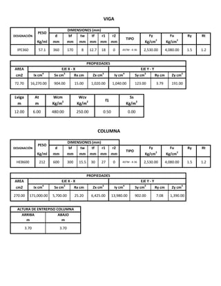
  • 1. ASTM ‐ A 36 TIPO TIPO ASTM ‐ A 36 DIMENSIONES (mm) PROPIEDADES d bf 18 0 2,530.00 4,080.00 1.5 1.2 Kg/cm2 mm mm mm Rx cm Zx cm3 VIGA Fy Fu Ry Rt Kg/cm2 Iy cm4 Sy cm3 Ry cm Zy cm3 IPE360 57.1 360 170 8 12.7 EJE Y ‐ Y Kg/ml mm mm mm cm2 Ix cm4 Sx cm3 tw tf r1 r2 AREA EJE X ‐ X DESIGNACIÓN PESO 191.00 Ss m m Kg/m2 Kg/m 2 Kg/m 2 Lviga At Wcm Wcv f1 72.70 16,270.00 904.00 15.00 1,020.00 1,040.00 123.00 3.79 0.00 COLUMNA DESIGNACIÓN PESO DIMENSIONES (mm) d bf tw tf r1 12.00 6.00 480.00 250.00 0.50 mm mm Kg/cm 2 HEB600 212 600 300 15.5 30 PROPIEDADES AREA EJE X ‐ X EJE Y ‐ Y Kg/cm2 r2 Fy Fu Ry Rt 27 0 2,530.00 4,080.00 1.5 1.2 Kg/ml mm mm mm mm 3.70 3.70 ARRIBA ABAJO m m Sy cm 3 Ry cm Zy cm3 270.00 171,000.00 5,700.00 25.20 6,425.00 13,980.00 902.00 cm2 Ix cm 4 Sx cm3 Rx cm Zx cm3 Iy cm4 7.08 1,390.00 ALTURA DE ENTREPISO COLUMNA
  • 2. TIPO Fy Fu Kg/cm 2 Kg/cm 2 ASTM ‐ A 36 2,530.00 4,080.00 PLANCHA PERNO TIPO A325 Ft Fv Kg/cm 2 Kg/cm2 6,330.00 4,220.00 AGUJERO ESTÁNDAR TIPO + db mm 3.00 28.575 1 1/4" 31.75 1 3/8" 34.925 1 1/2" 38.1 1 3/4" 44.45 2" 50.8 TIPO FExx Kg/cm 2 E60XX 4,220.00 ELECTRODODiametro pulg mm 1/2" 12.7 5/8" 15.875 de mm 22 30 32 38 45 58 2 1/8" 53.975 2 1/4" 57.15 2 1/2" 63.5 Pfoinicial mm 23 27 32 37 42 47 51 56 61 72 82 87 92 102 3/4" 19.05 7/8" 22.225 1" 25.4 1 1/8" 62 67 78 89 95 101 112 Pb mm 39 48 58 67 77 88 96 105 115 134 153 162 172 191 52 UNIÓN 4ES 256 266 220 140 150 120 Pfo 114 38 140 64 64 tbf bbf d tp bp g Pfi Pb Máximo Mínimo 19 mm Parametro UNIÓN 4E mm 10 235 152 1400 349 57 13 273 178 152 102 114 38 ‐ ‐ Máximo Mínimo mm mm 19 10 152 610 349 38 13 273 178 152 83 140 44 229 ‐ LIMITACIONES UNIÓN 4E UNIÓN 4ES UNIÓN 8ES mm mm mm 12.7 12.7 12.7 170 170 170 360 360 360 45 31 26 UNIÓN 8ES Máximo Mínimo mm mm 25 14 311 190 914 457 64 19 SI 50 64 64 50 67‐ ‐ COLOCADO COLOCADO UNIÓN 4E UNIÓN 4ES UNIÓN 8ES mm mm mm SI SI SI ‐ 381 229 152 127 51 41 95 89 44 51 41 Parametro tbf bbf d tp bp g Pfi Pfo Pb SI SI SI SI SI SI SI SI SI SI SI SI SI SI SI SI SI SI SI SI ‐ ‐ NO
  • 3. MOMENTO MAXIMO PROBABLE ALTURA DE PLANCHA 4E y 4Es = + + = x + = 1.21 47 52 112 122 1. 2. 2.1. Lst = tan 30° hst 1.31 Mpr Mpr = Cpr x Ry x Fy = Cpr = Fy + Fu ≤ 1.20 Cpr = 1.20 2 x FY 2 x FY Cpr = Fy + Fu = ANSI/AISC 358‐16 (2.4‐2) / Pag.  9.2‐8 de tfvigahst Pfo 2 hst dviga X1 mm 43 Cpr x Ry = 1.80 1 3/4" 47 1 1/4" 51 1 3/8" 56 1 1/2" 61 hplancha Diametro Pfoinicial pulg mm 1/2" 23 5/8" 27 3/4" 32 7/8" 37 1" 42 1 1/8" 72 2" 82 2 1/8" 87 2 1/4" ANSI/AISC 358‐16 (6.9‐1) / Pag.  9.2‐26 Tfviga mm 12.70 12.70 12.70 12.70 12.70 12.70 12.70 12.70 12.70 12.70 12.70 12.70 12.70 12.70 Pfo 57 62 67 71 76 81 92 102 107 Pfoinicial + Tfviga Tfviga 12.70 mm 92 2 1/2" 102 = Fy = 446.75 Fypr = 4,554.00 Kg/cm2 = 446.75 MPa Fupr = 7,344.00 Kg/cm2 = 720.45 MPa Mf Mpr = 1.00 % de carga = 100.00 %4,645,080.00 Kg x cm = 46,450.80 Kg x m = 455.68 KN x m x Zx ANSI/AISC 358‐16 (2.4.1) / Pag.  9.2‐7
  • 4. 8Es = + + + = x + 954 515 115 134 1196 724 172 191 57.15 63.5 2" 95 337 1034 619 153 162 105 256 234 7/8" 50 38 155 670 269 58 67 19.05 22.225 55 45 177 714 307 1 1/4" 64 872 218 796 444 655 409 96 105 760 347 77 88 25.4 28.575 mm Diametro 1/2" 36 22 97 554 169 40 30 118 596 205 39 48 12.7 15.875 89 44.45 1" 584 1 3/4" 2.2. hst Pfo de tfviga hplancha 2 Pfo de hst hplancha Lst pulg mm mm mm mm mm 378 Lst = hst tan 30° 45 1 3/8" 69 2 1/8" 100 38.1 31.75 34.925 1 1/2" 74 115 60 85 584 604 622 642 686 728 750 772 814 122 131 141 163 212 227 245 283 319 338 357 394 74.00 85.00 95.00 50.8 53.975 2 1/4" 3/4" 5/8" 1/2" pulg Pfo mm 36.00 40.00 45.00 194 105.00 115.00 de 95 mm 22 30 32 38 45 52 58 62 67 78 89 101 112 dviga Pb 5/8" mm 58 70 77 88 100 476 500 514 536 560 1 1/8" 1 1/4" 1 3/8" 1 1/2" 1 3/4" 2" 2 1/8" 2 1/4" 2 1/2" 1" 7/8" hst 50.00 55.00 60.00 64.00 69.00 112 hplancha mm Lst mm 184 195 206 227 101 hst 122 134 153 174 2 1/2" 3/4" 1 1/8" 100.00 78 52 200 95 67 112 418 58 297 ANSI/AISC 358‐16 (6.9‐1) / Pag.  9.2‐26 Pb mm 32 135 630 101 378 1116 357 1074 62 236 832 Diametro mm 12.7 15.875 19.05 22.225 25.4 28.575 31.75 34.925 38.1 44.45 50.8 53.975 57.15 63.5
  • 5. DISTANCIA DE LA CARA DE LA COLUMNA A LA ROTULA PLASTICA "Sh" 130.21 151.21 163.21 182.21 203.21 223.21 241.21 256.21 274.21 2 1/4" 2 1/2" 51.00 cm 2 = 2 1/8" 348.21 367.21 1 1/2" 1 3/4" 312.21 1 1/4" 1 3/8" 1" 1 1/8" Sh2Sh1 = = 180.00 mm 4E 18.00 cm dviga 3/4" 3. = 3 x bfviga 180.00 mm = tfviga 386.21 423.21 2" 7/8" 18.00 cm Sh = Lst + tp 4ES tp(INICIAL) = Sh 1/2" 5/8" =Min ( Sh1 Diametro pulg Sh mm 2.30 Sh2 ) ANSI/AISC 358‐16 ‐ (Sect. 2.3.) / Pag.  9.2‐5 ANSI/AISC 358‐16 ‐ (Sect. 2.3.) / Pag.  9.2‐5 x = ; tp = 29.21 mm 29.21 mm = 25.00 mm= = 510.00 mm = Mpe Vu Rotula plástica s0 Mf sh
  • 6. DISTANCIA ENTRE ROTULAS "Lh" DISTANCIA ENTRE ROTULAS = ‐ ‐ x 1 1/8" 374.686 2 1/8" 646.686 2 1/4" 682.686 2 1/2" 751.686 1 1/4" 11,143.79 1 1/2" 11,125.79 1 3/4" 11,087.79 2" Diametro Lh pulg mm 1/2" 11,220.00 5/8" 11,220.00 1 1/4" 11,220.00 3/4" 11,220.00 7/8" 11,220.00 1" 11,220.00 1 1/8" 11,220.00 1 1/4" 11,220.00 1 3/8" 11,220.00 1 3/8" 11,220.00 1 1/2" 11,220.00 1/2" 196.686 405.686 1 3/8" 436.686 1 1/2" 471.686 x tfviga = 27.69 mm 4. 5/8" 232.686 Diametro Sh pulg mm 1 3/4" 542.686 2" 611.686 tp(INICIAL) 8ES tp+ 3/4" 261.686 7/8" 296.686 = 2.18 1" 334.686 Sh = Lst Lh Lviga dcol 2 Sh 10,976.79 11,051.79 2 1/8" 11,032.79 2 1/4" 11,220.00 2 1/2" 11,220.00 4E 4ES Diametro Lh pulg mm 1/2" 11,269.79 5/8" 11,248.79 3/4" 11,236.79 7/8" 11,217.79 1" 11,196.79 1 1/8" 11,176.79 11,158.79 ANSI/AISC 358‐16 ‐ (Sect. 2.3.) / Pag.  9.2‐5 10,963.31 1 1/2" 10,928.31 tp = 27.69 mm 8ES Lh 1 3/8" Diametro 2 1/4" 10,717.31 2 1/2" 10,648.31 2" 11,220.00 2 1/8" 1 3/4" 10,857.31 2" 10,788.31 2 1/8" 10,753.31 2 1/4" 11,013.79 2 1/2" 1 3/4" pulg mm 1/2" 11,203.31 5/8" 11,167.31 3/4" 11,138.31 7/8" 11,103.31 1" 11,065.31 ANSI/AISC 358‐16 ‐ (Sect. 6.8.) / Pag.  9.2‐29 1 1/8" 11,025.31 1 1/4" 10,994.31
  • 7. CARGAS GRAVITACIONALES SOBRE LA VIGA. = x + x + x + x = x = = x = = x = = = = = CORTE GRAVITACIONAL "Vgravitacional" x CORTE ULTIMO "Vu" x Wcm 0.20 Sf1 Cv 2,880.00 Kg / m Wu 1.20 Cp 1.20 Pp Cp At 5. S At Ss 0.00 Kg / m Pp 57.10 Kg / m Vgravitacional = 4E 4ES 8ES Diametro Vgravitacional Diametro Vgravitacional Diametro Vgravitacional Wu 4,274.52 Kg / m f1 0.50 6. Wu Lh Cv At Wcv 1,500.00 Kg / m 2 41.93 KN x m 5/8" 23,980.06 5/8" 24,041.59 5/8" 23,867.45 3/4" 23,980.06 3/4" 24,015.94 3/4" 23,805.47 pulg Kg pulg Kg pulg Kg 1/2" 23,980.06 1/2" 24,086.47 1/2" 23,944.39 1 1/8" 23,980.06 1 1/8" 23,887.71 1 1/8" 23,563.96 1 1/4" 23,980.06 1 1/4" 23,849.24 1 1/4" 23,497.71 7/8" 23,980.06 7/8" 23,975.33 7/8" 23,730.67 1" 23,980.06 1" 23,930.45 1" 23,649.45 1 3/4" 23,980.06 1 3/4" 23,697.49 1 3/4" 23,204.90 2" 23,980.06 2" 23,620.55 2" 23,057.43 1 3/8" 23,980.06 1 3/8" 23,817.18 1 3/8" 23,431.45 1 1/2" 23,980.06 1 1/2" 23,778.71 1 1/2" 23,356.65 2 1/2" 23,980.06 2 1/2" 23,460.25 2 1/2" 22,758.22 7. 2 Mpr 2 1/8" 23,980.06 2 1/8" 23,579.94 2 1/8" 22,982.63 2 1/4" 23,980.06 2 1/4" 23,539.33 2 1/4" 22,905.69 Lh Vu = + Vgravitacional ANSI/AISC 358‐16 (6.8‐2) / Pag.  9.2‐29 ANSI/AISC 358‐16 ‐ Sect. 5.8.] / Pag.  9.2‐18 ANSI/AISC 358‐16 ‐ Sect. 5.8.] / Pag.  9.2‐27 ANSI/AISC 358‐16 ‐ Sect. 5.8.] / Pag.  9.2‐27 Wu VuVuMpe Mpe Lh
  • 8. MOMENTO MÁXIMO PROBABLE A LA CARA DE LA COLUMNA "Mf" 1 1/4" 31.75 1 3/8" 34.925 1 1/2" 38.1 1 3/4" 44.45 2 1/2" 63.5 50.8 53.975 57.15 63.5 4E Diametro pulg mm 1/2" 12.7 5/8" 15.875 3/4" 19.05 7/8" 22.225 1" 25.4 1 1/8" 28.575 1 1/4" 31.75 1 3/8" pulg 4ES 32,174.65 Kg 44.45 2 1/2" 32,260.06 1 1/2" 38.1 1 3/4" 44.45 2" 50.8 2 1/8" 53.975 2 1/4" 57.15 Diametro mm 12.7 7/8" 22.225 1" 25.4 1 1/8" 28.575 53.975 2 1/4" 57.15 2 1/2" 5/8" 15.875 3/4" 1" 25.4 28.575 1 1/4" 63.5 8ES 2" 50.8 2 1/8" 2 1/8" 53.975 15.875 19.05 22.225 25.4 28.575 31.75 34.925 38.1 44.45 50.8 53.975 57.15 63.5 15.875 19.05 22.225 25.4 28.575 3/4" Kg 1/2" 32,260.06 32,329.89 32,236.73 Vu Vu VuDiametro mm 12.7 Kg Diametro pulg mm 1/2" 12.7 31,947.6831.75 34.925 38.1 15.875 7/8" 32,260.06 32,256.97 32,097.68 1" 32,260.06 32,227.62 32,045.20 5/8" 32,260.06 32,300.40 32,186.52 3/4" 32,260.06 32,283.57 32,146.2019.05 22.225 25.4 34.925 1 1/8" 32,260.06 5/8" 15.875 3/4" 19.05 31,482.75 8. 2 1/8" 32,260.06 32,000.44 31,621.97 2 1/4" 32,260.06 31,974.36 31,574.05 1 3/4" 32,260.06 32,076.22 31,761.49 2" 32,260.06 32,026.57 31,668.75 28.575 1 3/8" 32,260.06 32,153.80 31,905.31 1 1/2" 32,260.06 32,128.82 32,199.72 31,990.17 1 1/4" 32,260.06 4E 4ES Diametro pulg mm 1/2" 12.71/2" 52,257.61 1/2" 50,660.48 Mf = Mpr + Vu x Sh 52,257.61 3/4" 51,719.80 54,863.01 7/8" 52,257.61 7/8" 52,328.34 55,973.73 5/8" 52,257.61 5/8" 51,334.94 53,940.15 Mf Mf Mf pulg Kg x m pulg Kg x m Kg x m 19.05 7/8" 22.225 52,791.31 Diametro mm 12.7 1 1/2" 52,257.61 1 1/2" 55,260.84 61,477.61 1 3/4" 52,257.61 1 3/4" 56,465.32 63,687.32 1 1/4" 52,257.61 1 1/4" 54,211.65 59,411.52 1 3/8" 52,257.61 1 3/8" 54,688.93 60,383.40 44.45 31.75 1 3/8" 34.925 1 1/2" 38.1 1 3/4" 44.45 31.75 34.925 38.1 1" 52,257.61 1" 52,999.77 57,175.88 1 1/8" 52,257.61 1 1/8" 53,638.10 58,437.07 68,005.96 2 1/2" 52,257.61 2 1/2" 59,961.23 70,115.94 2" 52,257.61 2" 57,602.77 65,822.13 2 1/8" 52,257.61 2 1/8" 58,201.68 66,900.29 50.8 53.975 57.15 63.5 2" 50.8 2 1/4" 52,257.61 2 1/4" 58,799.62 2 1/2" 63.5 1 1/8" ANSI/AISC 358‐16 (6.8‐1) / Pag.  9.2‐29 8ES 31,857.65 31,923.71 2 1/4" 57.15
  • 9. DISTANCIAS "h" Para 4E y 4ES 85.00 ‐ Pfi 105.30 115.30 389.95 393.95 398.95 225.65 468.95 69.00 9. tfviga 2 h1 = dviga ‐ 2 1/2" 115.00 Pfi mm 36.30 40.30 45.30 50.30 55.30 60.30 64.30 69.30 74.30 85.30 95.30 100.30 1 3/8" ho 300.65 295.65 tfviga = dviga ‐ tfviga 2 + Pfo 1 1/2" 74.00 1 3/4" 3/4" 45.00 7/8" 50.00 60.00 1 1/4" 64.00 Pfo pulg mm ‐ mm 304.65 ho Diametro 4E y 4ES 266.65 427.95 255.65 438.95 245.65 448.95 240.65 453.95 235.65 458.95 290.65 403.95 285.65 408.95 280.65 413.95 276.65 417.95 271.65 422.95 h1 2 1/4" 105.00 1" 55.00 1 1/8" 2" 95.00 1/2" 36.00 5/8" 40.00 2 1/8" 100.00 mmmm 12.7 15.875 19.05 22.225 25.4 28.575 31.75 34.925 38.1 44.45 50.8 53.975 57.15 63.5 ANSI/AISC 358‐16 (6.8) / Pag.  9.2‐31
  • 10. Para 8ES Diametro 8ES 5/8" 40.00 40.30 441.65 393.65 3/4" 45.00 45.30 456.65 398.65 48.00 58.00 pulg mm mm mm mm 1/2" 36.00 36.30 428.65 389.65 mm 39.00 h2 1 1/8" 60.00 60.30 501.65 413.65 1 1/4" 64.00 64.30 513.65 417.65 88.00 96.00 7/8" 50.00 50.30 470.65 403.65 1" 55.00 55.30 485.65 408.65 67.00 77.00 1 3/4" 85.00 85.30 572.65 438.65 2" 95.00 95.30 601.65 448.65 134.00 153.00 1 3/8" 69.00 69.30 527.65 422.65 1 1/2" 74.00 74.30 542.65 427.65 105.00 115.00 h1 = dviga ‐ tfviga 2 + Pfo + Pb 191.00 2 1/8" 100.00 100.30 615.65 453.65 2 1/4" 105.00 105.30 630.65 458.65 162.00 h3 = h2 h3 h4 mm mm h2 = h1 ‐ Pb 304.65 265.65 252.65 237.65 223.65 208.65 192.65 180.65 166.65 151.65 121.65 92.65 78.65 63.65 34.65 Pb 172.00 h1 2 1/2" 115.00 Pfi 300.65 295.65 290.65 285.65 280.65 276.65 271.65 266.65 255.65 245.65 240.65 235.65 225.65 h4 = h3 ‐ Pb 659.65 468.65 ‐ Pfo Pfi ‐ Pfo ‐ tfviga 115.30 mm 12.7 15.875 19.05 22.225 25.4 28.575 31.75 34.925 38.1 44.45 50.8 53.975 57.15 63.5 ANSI/AISC 358‐16 (6.8) / Pag.  9.2‐32
  • 11. DIAMETRO DEL PERNO REQUERIDO POR TRACCIÓN. x x x x ( + ) x x x x ( + + + ) = x Para estado límite no ductil x x = : = = = = Para: 4E Y 4ES 8ES Fnv Fnv 6330 kg/cm² Øn 0.90 Fnt ANSI/AISC 358‐16 (2.4‐1) / Pag.  9.2‐7 Fnt ho h1 2 Mf Para: 10. db req'd = Π Øn nb 4 Vu < Øn x Rn Øn x 28.99508 pulg mm mm 16.44 db2 req'ddb2 req'd mm 16.44 16.44 16.44 16.44 16.44 h1 db1 req'd = h4 Ab Ab 2 Mf Π Øn Fnt h2 h3 16.44 db2 req'd ANSI/AISC 358‐16 Numero de pernos en zona comprimida. 16.44 5/8" 15.875 28.73797 nb 8 5/8" 15.875 4ES 8ES nb pulg mm mm 3/4" 19.05 21.01204 Vu > = 16.44 16.44 16.44 nb x Diametro db1 req'd Diametro db2 req'd mm 11.62 11.61 11.61 11.60 11.59 19.05 28.84549 mm 16.41 16.40 29.8166128.99508 22.225 21.22367 20.83457 11.56 11.55 11.54 > Øn nb Fv ANSI/AISC 358‐16 (6.8‐3) / Pag.  9.2‐29 ANSI/AISC 358‐16 (6.8‐4) / Pag.  9.2‐29 x "8ES" 4E 0.90 Ab 4 Π Øn 4,220.00 Kg/cm2 1/2" 16.42 16.42 16.46 16.45 16.45 16.44 16.43 12.7 28.99508 1/2" 12.7 28.54856 1/2" 12.7 20.6115 3/4" 19.05 11.58 11.57 db1 req'd Diametro db1 req'd 1 3/8" 34.925 28.99508 23.754 16.38 16.36 16.43 3/4" 25.4 pulg mm mm 1 1/8" 28.575 21.68566 1 3/4" 44.45 22.63888 57.15 30.75649 2 1/4" 57.15 23.39386 16.38 16.37 1 3/8" 34.925 29.66192 1 3/8" 34.925 22.04384 11.52 11.51 11.50 11.49 7/8" 22.225 28.99508 7/8" 22.225 29.0147 7/8" 1" 25.4 28.99508 1" 25.4 29.20025 1" 21.45037 2 1/8" 53.975 28.99508 2 1/8" 53.975 30.59971 2 1/8" 53.975 23.20291 2 1/4" 57.15 28.99508 2 1/4" 1 1/2" 38.1 1 1/4" 31.75 28.99508 1 1/4" 31.75 29.5322 1 1/4" 31.75 21.86572 1 1/2" 38.1 1 1/2" 38.1 22.24267 16.44 16.44 16.44 2 1/2" 63.5 2" 50.8 28.99508 2" 50.8 30.44187 2" 50.8 23.01518 (6.8‐11.) / Pag.  9.2‐33 1 3/4" 44.45 28.99508 1 3/4" 44.45 30.13981 1 1/8" 28.575 28.99508 1 1/8" 28.575 29.37557 5/8" 15.875 28.99508 "4E" y "4ES" 2 1/2" 63.5 28.99508 2 1/2" 63.5 31.05881
  • 12. = = = ALTURA "Yp" 4E = = = = = = = = = = x + + x = = x + = = ( ; ) = = ‐ x x ‐ = = x ( + ) + = = = = ( ; ) = = + x = = + = > = = = (Tabla 6.2) / Pag.  9.2‐31 g1 dp twcolumna 2 r 133.00 mm Pfo 2 twcolumna 143.50 mm g3 bfviga 170.00 mm 2 7/8" bp2 bfviga 50.00 mm 220.00 mm pulg 1/2" 5/8" 53.975 57.15 63.5 29.00 28.575 31.75 34.925 29.00 50.8 2 1/8" twcolumna 11. 11.1. S = 1 2 x 29.66 1 1/2" 38.1 2 1/4" 2 1/2" db req'd mm 29.00 29.00 29.00 29.00 29.00 29.00 29.00 29.00 3/4" 7/8" 1" 1 1/8" 1 1/4" 1 3/8" 1 1/2" 1 3/4" 2" 30.14 2" 50.8 30.44 2 1/4" 57.15 g max g5 g6 g g2 bfviga 170.00 mm Diametro perno 1 1/4" g6 2 1/2" 63.52 1/2" 63.5 31.06 Diametro del perno a utilizar Pfo 276.65 mm 203.00 mm 140.00 mm g5 bfcolumna max g1 2 31.75 mm Diametro del perno a utilizar 7/8" 22.23 mm1 1/4" 31.75 mm Pfi 64.30 mm = 94.66 mm 31.75 mm1 1/4" Diametro del perno a utilizar 64.00 mm h1 pulg mm mm 1/2" 12.7 28.55 5/8" 15.875 28.74 3/4" 19.05 28.85 1 1/8" 23.75 23.20 bp 44.45 29.20 Diametro 4E 19.05 22.225 25.4 29.00 12.7 15.875 22.225 29.01 25.4 Diametro db req'd Diametro db req'd pulg mm mm 1/2" 12.7 29.00 29.00 22.225 21.22 1" 25.4 21.45 1 1/2" 38.1 22.24 1 1/8" 8ES 28.575 21.69 1 1/4" 31.75 21.87 1 3/8" 34.925 22.04 19.05 21.01 7/8" r twcolumna 139.00 mm bp 256.00 mm 23.39 2 1/8" 53.975 1 3/4" 44.45 22.64 2" 50.8 bp1 Pfi Pfi mm 1" 20.61 5/8" 15.875 20.83 3/4" 1.25 dp 28.575 29.38 1 1/4" 31.75 29.53 1 3/8" 34.925 23.02 x 29.82 1 3/4" 2 1/8" 53.97530.60 2 1/4" 57.15 30.7629.00 38.1 44.45 4ES g SSi 2 dg S S ho 417.95 mm 94.66 mm de 58.00 mm 2 de 256.00 mm 51.00 mmPfoinicial ANSI/AISC 358‐16 g3 g2 135.00 mm
  • 13. 4ES = = = = = = = = = = = x + + = = ‐ x x ‐ = = ( ; ; ) = = ( ; ) = = x ( + ) + = = + x = = + = > = = = x Caso 1 ≤ Caso 2 > 8ES = = = Caso 1 (Tabla 6.3) / Pag.  9.2‐32 Caso 2 (Tabla 6.4) / Pag.  9.2‐33 bp2 x h1 x 1 gPfi +( Diametro perno 1 1/4" 31.75 mm x h1 x 2 ho x ( Pfi 1 Pfo ) 1 2 ‐ + 2bp + SYp = Pfoinicial 51.00 mm Pfi 64.30 mm Pfo 64.00 mm Yp = 1,559.07 mm 11.2. S = 1 x Bp x g = 99.87 mm 1 S ) + 2 S S 99.87 mm 2 twcolumna 149.25 mm 150.00 mm de 58.00 mmh1 276.65 mm ho 417.95 mm g1 bfviga 170.00 mm g2 Pfoinicial bfviga 50.00 mm 220.00 mm g3 bfcolumna 2 1.25 dp twcolumna 203.00 mm g max 139.00 mmtwcolumna Yp1 = 3,372.93 mm ( ) Yp1 = x h1 x ( 1 + ) + ho x ( 1 )+ bp1 g 2 de 266.00 mm bp 266.00 mmSi Pfi S Pfi Pfo 2 bp 2 1 S S 1 2 g + x h1 x ( Pfi + Pfi Yp2 = bp x h1 x ( 1 + 1 ) + ho x ( 1 + 3,884.57 mm de S Yp1 de S x ( S + Pfo ) 2 Pfi S Pfo gS h1 x ( Pfi + S ) + ho 1 ) + Yp2 2 de 38.00 mm Yp2 = ANSI/AISC 358‐16 ANSI/AISC 358‐16 g4 Yp = 3,372.93 mm 11.3. 7/8" 22.23 mm g4 g5 2 x ho x+ de +( Pfo ))S S = 1 x Bp x g = 76.68 mm Diametro perno dp min g1 g2 g3 149.25 mm g5 2 dg r
  • 14. = = = = = = = = = = = x + + = = ‐ x x ‐ = = ( ; ; ) = = ( ; ) = = x ( + ) + = = + x = = + = > = = = x x x x x Caso 1 ≤ Caso 2 > Caso 1 Caso 2 226.00 mmg3 bfcolumna 2 1.25 dp twcolumna Yp1 = bp x h1 x 111.73 mm 120.00 mm bp1 g 2 de 196.00 mm bp 220.00 mm g1 bfviga 170.00 mm g2 Pfoinicial 2 twcolumna bp2 bfviga Pfi 50.30 mm Pfo 50.00 mm 2 ( 1 ) S ( 1 2 de ) + h2 x ( 1 Pfo + h2 ) 4 h1 x ) + h3 x ( 220.00 mm Yp = 4,622.33 mm S S + 1 ) Pfi + h4 x Pfi S S 76.68 mm 50.00 mm Pb + 2 g x Si Pfi Pfoinicial 37.00 mm ( de + ) 4 + h3 x ( Pfi + Pb ) 4 ( Pfo + Pb )+ 3 4 h2 x + 3 Pb ( S +h4 x Yp2 = bp x h1 2 x ( 1 S Yp1 = 4,622.33 mm ) + h2 + Pb2 + g 2 x h1 x ) 4 + Pb 2 + g x ( Pfi + Pb ) 4 + h4( Pfo + 3 Pb ) 4 + h3 S 1 ) Pfi + h4 x ( 1 ) x + h3 x ( ( S + Pb ) x g 4 Yp2 = 4,919.70 mm Yp1 de S Yp2de + 3 Pb S x ( 1 ) Pfo ( 120.00 mmdg r twcolumnag max g4 g5 h1 470.65 mm h2 403.65 mm h3 290.65 mm Pb 223.65 mm 67.00 mm g2 g3 111.73 mmg1g4 min h4 g5 2 dp
  • 15. ESPESOR DE PLANCHA EXTREMA"tp" x = x x = ‐ tfvig x ESPESOR DE PLANCHA RIGIDIZADORES "tpr" = ANSI/AISC 358‐16 (2.4‐1) / Pag.  9.2‐7 TIPO Diametro pulg mm 4E 1 1/4" 31.75 ESPESOR DE PLANCHA EXTREMA A UTILIZAR 4ES 1 1/4" 31.75 8ES 7/8" TIPO Diametro pulg mm 4E 1 1/4" 31.75 h3 ‐ 470.65 Pt x 22.23 tp mm 45.00 31.00 26.00 tp mm 45.00 31.00 26.00 Mnp = 2 x Pt x ( h1 + h2 )+ h3 + h4 h2 x h4 ‐ ‐ ( ho + h1 ) ho mm 417.95 417.95 h1 mm 276.65 276.65 Mnp Kg x m 69,621.89 69,621.89 db2 4 Yp mm 1,559.07 3,372.93 Π 4,622.33403.65 290.65 223.65 4E y 4ES 8ES 4ES 1 1/4" 31.75 8ES 7/8" 22.23 Pt Kg 50,116.54 50,116.54 24,557.10 Mnp = 2 x Fyp 2530 kg/cm² Ød 1.00 tp mm 39.00 27.00 24.00 Mf Kg x m 52,257.61 54,211.65 7/8" 31.75 22.23 1,559.07 Yp mm 3,372.931 1/4" TIPO mm 0.56 x Fyplancha E 12. tp = 1 1/4" 31.75 59,411.52 68,199.99 mm mm mm ‐ ‐ ‐ ‐ 4E 4ES 8ES Diametro pulg 4,622.33 ANSI/AISC 358‐16 (6.8‐5) / Pag.  9.2‐29 Pt = Fnt 22.23 10.00 hst mm ‐ 122.00 155.00 tpr2 ≥ 0.56 x E Fyplancha hst TIPO Diametro tp2 pulg mm mm 8.00 8ES 7/8" tp mm ‐ 8.00 10.00 tp1 mm ‐ 8.00 8.00 RIGIDIZADOR A UTILIZAR ESPESOR DE PLANCHA E 4E 1 1/4" 31.75 2,100,000.00 Kg/cm2 1.11 Mf Ød Fyp Yp ANSI/AISC 358‐16 (6.8‐10) / Pag.  9.2‐33 ANSI/AISC 358‐16 (6.8‐10) / Pag.  9.2‐32 ‐ 4ES 1 1/4" 31.75 13. tpr1 = twviga x Fyplancha Fyviga = 8.00 mm hst tpr ≤ Ffu Ffu = Mf dvig156,094.58 171,066.87 Kg 150,468.21
  • 16. FUERZAS EN LAS ALAS DE LA VIGA "Ffu" ‐ VERIFICACIÓN DE ESPESOR DE PLANCHA PARA" 4E" = Para estado límite ductil x x x x = x x x x 31.75 256.00 19.00 4ES 1 1/4" 31.75 0.90 mm 7/8" 22.23 220.00 23.00 3.00 3.00 3.00 + db X1 mm 186.50 196.50 169.55 4E 1 1/4" Ffu ≤ Øn x 2 0.6 x Fuplancha x 266.00 19.00 8ES tp x X1 tp ≥ 2 Øn 0.6 Fuplancha X1 TIPO Diametro bp tp pulg mm mm mm Ffu Øn bp = 256.00 mm tp 0.6 x x bpFyplancha x tp ANSI/AISC 358‐16 (6.8‐7) / Pag.  9.2‐30 tfviga mm 256.00 266.00 220.008ES 7/8" 22.23Ød 0.6 Fyplancha bp Ffu 171,066.87 360 12.7 360 12.7 ANSI/AISC 358‐16 Ffu ≤ Øn x Rn ANSI/AISC 358‐16 2 (6.8‐8) / Pag.  9.2‐28 TIPO Diametro pulg mm 4E 1 1/4" 31.75 4ES 1 1/4" 31.75 dbg : diametro del agujero Rn = 0.6 x Fuplancha x An An = tp x X1 X1 = bp ‐ 2 x ( +db + db ) Rn = 0.6 x Fuplancha x tp x X1 20.00 20.00 26.00 bp mm Ød 1.00 ANSI/AISC 358‐16 (2.4‐1) / Pag.  9.2‐7 Ffu ≤ 2 Ød x 0.6 x Fyplancha x bp x tp ≥ 2 Ffu 2 ≤ xØd Rn Rn = tp (6.8‐6) / Pag.  9.2‐30 14. Ffu = dviga tfviga Mf TIPO 4E 4ES 8ES Mf Kg x m 52,257.61 54,211.65 59,411.52 dviga mm 360 12.7 Ffu Kg 150,468.21 156,094.58 15. mm
  • 17. RESUMEN PLANCHA EXTREMA SOLDADUDA ALAS DE LA VIGA x x x ‐ = x x = = x ‐ = SOLDADUDA ALMA DE LA VIGA = x x = = = ( ) 24.00 TIPO Ffu Kg 4E 150,468.21 4ES 156,094.58 8ES 171,066.87 =Fced viga 105,212.57 65,854.30 Kg Ffilete = Ffu Fced viga‐ Øw = 0.60 x Cpr Ry Ffilete 0.7071 ØFw Lv1;Lv2 31 Dfviga = 13.00 mm tp mm 45 Lv min 604 670 Øw 0.60 mm ‐ 8 Rwpenetración = 91,109.80 Kg RIGIDIZADOR ‐ 122 155 tp 10 Lst 18. ØFw 0.75 = 64,984.78 Øw = 167.30 mm Fyviga x bfviga x Lv1 = dviga 2 ‐ tfviga 11 13 150,468.21 Df3viga 4ES 8ES Ffu Kg 79,957.07 10 171,066.87 Ffu mm 59,358.41 FExx 1,899.00 Kg/cm2 Kg 26 64 50 64 58 Pfi = 98,320.86 Kg x Lef bfviga twviga Rwpenetración = 156,094.58 FExx x bfviga TIPO 4E tfviga = 91,109.80 Kg Rwpenetración mm Sxviga Fyviga dviga tfviga tfviga x Df1viga 16. Dfviga = 17. g bp mm mm 140 256 hplancha mm 604 mm 19.00 21.00 64.30 50.30 58 38 150 120 266 220 TIPO 4E 4ES 8ES 1 1/4" 31.75 Lef ØFw 0.75 Øw FExx 21,899.00 Kg/cm2 ‐ 212 269 mm hst mm 332.00 mm = Ffilete Kg 84,613.91 90,240.28 22.23 Pfo de mm 34.75 25.237/8" PERNO PLANCHA EXTREMA Diametro pulg mm 1 1/4" 31.75 mm 64.30 mm dbg 34.75
  • 18. x x x x x x x x = ( ; ; ) PLANCHA EXTREMA Desgarramiento por los pernos  = ( ; ) : : Desgarramiento por los pernos internos = ‐ = ( ; ) : TIPO Diametro pulg mm 4E 1 1/4" 31.75 4ES 1 1/4" 31.75 8ES 7/8" 22.23 Vu Kg Dw3viga mm 8 8 8 mm 8 32,260.06 32,174.65 32,097.68 8 Dw1viga mm 8 8 206.80 239.85 Dwviga 8 MaxDwviga Dw1viga Dw2viga Dw3viga 8 Vu Dw2viga = 0.9 Fyviga Ry twviga 1.5 ØFw 1.4142 Dw2viga mm 7 7 7 tp mm SOLDADURA  MÍNIMA mm 167.30 167.30 167.30 Lv2 mm 206.80 Dw3viga Lv2 0.7071 ØFw Dw1viga = dperno ) 45 31 26 Lv mm 167.30 167.30 167.30 tfviga ‐ Lv1 ( Pfi + 2 x 4E 1 1/4" 31.75 4ES 1 1/4" 31.75 8ES 7/8" 22.23 Pfi mm 64.30 64.30 50.30 Lv2 = ‐dviga 2 x TIPO Diametro pulg mm Lc1 = de ‐ da 2 TIPO Diametro pulg mm Fup rno2 Kg 19. Vu < Øn x Rn = Øn x (ni) x rni + ANSI/AISC 358‐16 (6.8‐12.) / Pag.  9.2‐34 RESISTENCIA AL APLASTAMIENTO Y DESGARRAMIENTO POR CORTE DE LA PLANCHA Y EL ALA DE LA COLUMNA: rno 1 1/4" 31.75 4ES 1 1/4" 31.75 Øn x (no) x 96,377.76 56,583.07 rno Kg 89,505.00 61,659.00 32,317.27 rno 19.1. tp mm 45.00 31.00 26.00 = 1.2 x Lc1 x tp x Fup 8ES 7/8" 22.23 mm 58.00 58.00 19.1.1. 89,505.00 61,659.00 4E 19.1.2. Lc2 = x Lc2 x tp x Fuprni1 = 1.2 rni2 = 2.4Pfi + 32,317.27 Kg rno1 rno1 rno2 = 2.4 x db x tp x min rno1 rno2 rno1 rno2 Resistencia al aplastamiento Desgarramiento por los pernos  38.00 de da mm 34.75 34.75 25.23 Lc1 mm 40.63 40.63 25.39 139,903.20 Pfo + tfviga ‐ da x db x tp x Fup Lc3 Pb da Lc3 min Lc2 Lc3
  • 19. = ( ; ) : : Chequeo por corte = ALA DE LA COLUMNA Desgarramiento por los pernos  = ( ; ) : : Desgarramiento por los pernos internos x db x tp x Fup 8ES 7/8" 22.23 38.00 25.23 25.39 30.00 37,289.16 65,288.16 37,289.16 19.2.2. Lc2 = Pfi + Pfo + tfviga ‐ da rni1 = 1.2 x Lc2 x tp x Fup rni2 = 2.4 4E 1 1/4" 31.75 58.00 34.75 40.63 30.00 59,670.00 93,268.80 59,670.00 4ES 1 1/4" 31.75 58.00 34.75 40.63 30.00 59,670.00 93,268.80 59,670.00 TIPO Diametro de da Lc1 tfcolumna rno1 rno2 rno pulg mm mm mm mm mm Kg Kg Kg = 2.4 x db x x 2 rno min rno1 rno2 rno1 Desgarramiento por los pernos  rno2 Resistencia al aplastamiento Fucolumna Fucolumnatfcolumna tfcolumna 19.2.1. Lc1 = de ‐ da rno1 = 1.2 x Lc1 x x rno2 64.30 rni2 rni Kg Kg 139,903.20 139,903.20 96,377.76 234,090.00 161,262.00 Lc4 mm 106.25 106.25 1 1/4" rni1 Kg Diametro pulg mm 31.75 1 1/4" 31.75 da mm 34.75 34.75 Pfi mm 19.1.3. 41.7850.30 Pfo mm 64 64 50 Lc2 mm 106.25 106.25 87.78 TIPO 4E 4ES 8ES 7/8" 22.23 25.23 64.30 Øn rni min rni1 rni2 rni1 rni2 Resistencia al aplastamiento Desgarramiento por los pernos internos x Rn = Øn x (ni) x rni + Øn x (no) x 96,377.76 53,177.90 56,583.07 53,177.90 < Øn x Rn Si Chequea Si Chequea Si Chequea Pb mm ‐ ‐ 67 Lc3 mm ‐ ‐ 41.775 TIPO Diametro pulg mm 4E 1 1/4" 31.75 4ES 2 2 4 (ni) (no) 19.2. Vu Kg 32,260.06 32,174.65 32,097.68 rno 2 2 4 Øn Rn Kg x 412,934.76 284,466.17 307,782.63 Vu 1 1/4" 31.75 8ES 7/8" 22.23 Øn 0.90 Vu < ANSI/AISC 358‐16 (6.8‐12.) / Pag.  9.2‐33
  • 20. = ‐ = ( ; ) = ( ; ) : : Chequeo por corte = ALTURA "Yc" PARA 4E Y 4ES SIN RIGIDIZADOR DE ALA x (Tabla 6.5) / Pag.  9.2‐34 + C 4 ) + 54,211.65 Mf Kg x m 2,873.99 141 106.07 2,758.68 g mm 140 150 + g 2 1 1/4" 31.75 ( S 20. 4E 1 1/4" 31.75 32,260.06 2 2 275,289.84 h1 = dviga ‐ tfviga ‐ tfviga ‐ Pfi ANSI/AISC 358‐1620.1. tfviga Si Chequea 4ES 1 1/4" 31.75 32,174.65 2 2 275,289.84 Si Chequea 8ES 7/8" 22.23 32,097.68 4 4 355,133.81 Si Chequea (6.8‐12.) / Pag.  9.2‐33 Øn 0.90 TIPO Diametro Vu (ni) (no) Øn x Rn Vu < Øn x Rn pulg mm Kg Kg 8ES 7/8" 22.23 25.23 50.30 50 67 87.78 41.775 41.78 61,359.12 65,288.16 61,359.12 19.2.3. Vu < Øn x Rn = Øn x (ni) x rni + Øn x (no) x rno ANSI/AISC 358‐16 4E 1 1/4" 31.75 34.75 64.30 64 ‐ 106.25 ‐ 106.25 156,060.00 93,268.80 93,268.80 4ES 1 1/4" 31.75 34.75 64.30 64 ‐ 106.25 ‐ 106.25 156,060.00 93,268.80 93,268.80 rni2 Resistencia al aplastamiento TIPO Diametro da Pfi Pfo Pb Lc2 Lc3 Lc4 rni1 rni2 rni pulg mm mm mm mm mm mm mm mm Kg Kg Kg Lc3 Pb da Lc3 min Lc2 Lc3 rni min rni1 rni2 rni1 Desgarramiento por los pernos internos mm 141 + x h1 x ( 2 g S + 3 C 4 ) + = bfcol x h1 2 x ( ) 1 S + ho x ( ho x x bfcolC = Pfi Pfo C TIPO 4ES 1 1/4" 31.75 h1ho mmmm + Pfo 2 tfcolumna req mm 28.24 29.36 2 ho = dviga ‐ 277418 tfviga S Yc1 277418 102.47 Diametro pulg mm 4E + + S = 1 2 S Yc1 1 ) mm mm C2 2 x g 52,257.61
  • 21. x x x = CON RIGIDIZADOR DE ALA = ‐ ‐ = x x x ALTURA "Yc" PARA 8ES SIN RIGIDIZADOR DE ALA x x xØd Fycolumna Yc (6.8‐13.) / Pag.  9.2‐34 120.00 113.00 94.87 3,641.87 Mf tfcolumna req Kg x m mm 59,411.52 26.75 C ) + g g 4 2 pb mm 67.00 S + S pb 2 + h3 x ( pb + C ) 2 tfcolumna req = 1.11 Mf ANSI/AISC 358‐16 + 2 x h1 x ( Pb + C ) + h2 x ( + S x h1 x ( 1 ) + h4 x ( 1 ) 2 S S + 2 xh4 = 1.11 Mf ANSI/AISC 358‐16 Ød Fycolumna Yc (6.8‐13.) / Pag.  9.2‐34 4ES 4,185.8264.30 64 + 21. 21.1. ANSI/AISC 358‐16 (6.8.) / Pag.  9.2‐35 Yc1 = bfcol 1 1/4" 31.75 418 277 150 141 106.07 Pfi Pfo mm mm 64.30 64 + 2 x h1 x ( S g TIPO Diametro ho g 52,257.61 23.10 54,211.65 23.84 tfcolumna req 4E 1 1/4" 31.75 418 277 140 141 102.47 4,297.09 psi ) + ho x psi Ød 1.00 ( 1 S + 1 ) pso ANSI/AISC 358‐16 (6.8‐13.) / Pag.  9.2‐33 64 64 63.85 64 63.85 64 ) + ho x 2 h1 Mf tfcolumna req Kg x m mm ANSI/AISC 358‐16 (6.8.) / Pag.  9.2‐34 Si psi > S Use psi S mm mm mm mmmm mm Yc2 pulg mm mm mm tfviga 2 psi = Pfi ‐ ts tfviga 20.2. ts1 ≤ tfcolumna ts 13.00 mm Pso Psi tfcolumna req = 1.11 Mf Ød Fycolumna Yc C S pso = Pfo ‐ ts Psi1 mm ( S + pso ) Yc2 = bfcol x h1 x ( 1 2 S + 1 mm mm mm mm 470.65 403.65 290.65 223.65 S Yc1 mm mm TIPO Diametro pulg mm g C mm mm 8ES 7/8" 22.23 h1 h2 h3 h4
  • 22. CON RIGIDIZADOR DE ALA x x x RESUMEN ESPESOR DE ALA COLUMNA REQUERIDO. RESISTENCIA DE LAS ALAS DE LA COLUMNA ( ‐ ) RESISTENCIA A LA CEDENCIA LOCAL DEL ALMA DE LA COLUMNA = = = = = + x + x = =2 w mm 0.00 604.00 0.00 0.00 115.00 0.00 RIGIDIZADOR SIN DE ALA tfcolumna req mm 29.00 30.00 27.00 CON RIGIDIZADOR DE ALA tfcolumna req mm 24.00 24.00 22.00 Rigidizador ala columna A mm Diferencia mm 0.00 0.00 0.00 mm tral 0.00 0.00 0.00 h 59,411.52 21.22 Pfi Pfo Psi1 Pso Psi mm mm mm h3 x ( 1 ) Psi + h4 x ( 1 mm mm 50.30 50 50.15 49.85 50 x ( ) + 1 1/4" 31.75 4ES 1 1/4" 31.75 8ES 7/8" 22.23 tfcolumna mm 30.00 30.00 30.00 22. TIPO Diametro pulg mm 4E TIPO Diametro Yc2 Mf tfcolumna req pulg mm mm Kg x m mm + g 4 tfcolumna req = 1.11 Mf Ød Fycolumna Yc Pso Psi g + x h1 x ( 8ES 7/8" 22.23 5,790.52 (6.8‐13.) / Pag.  9.2‐33 + pb 2 ANSI/AISC 358‐16 21.2. ANSI/AISC 358‐16 (6.8.) / Pag.  9.2‐35 + ) + h3 x ( + pb ) 4 ( S 3 x pb 4 + ) S Yc2 = x h1 )+ h4 x 2 pb +S ) + h2 x ( 4 bfcol 1 1 3 x pb +h2 x ( ) 2 S Pso dcolumna N tfviga dcolumna Ct 0.50 So < Ct = 1.00 Ct 1.00 So ≥ ØdRn1 = dviga tfviga ØdMcf ANSI/AISC 358‐16 (6.8‐15.) / Pag.  9.2‐35 = 188,427.45 Kg Ffu = 150,468.21 Kg ANSI/AISC 358‐16 (6.8‐14.) / Pag.  9.2‐35 ØdMcf = Ød x Fycolumna x Yc1 x tfcolumna 2 = 6,544,085.48 Kg x cm 23. 24. So 3,700.00 mm 600.00 mmdcolumna tp2 Dfviga 13.00 mm38.70 mm
  • 23. = + = = x ( x + + x ) x x x RESISTENCIA AL PANDEO DEL ALMA DE LA COLUMNA = ‐ x = = = = = x x x RESISTENCIA AL APLASTAMIENTO LOCAL DEL ALMA DE LA COLUMNA Cuando Ffu se aplica a una distancia mayor o igual a dcolumna / 2 desde el extremo de la columna "So" = = = x x 18.00 19.00 dcolumna N 8ES 7/8" 22.23 TIPO Diametro pulg mm 4E 25. ANSI/AISC 358‐16 (6.8‐17.) / Pag.  9.2‐37 h dcolumna Kc2 Ø Ct 1 1/4" 31.75 4ES Kc rcolumna tfcolumna 57.00 mm Ct 6 Kc N 2 tp Fycolumna twcolumna ØdØdRn2 1 1/4" 31.75 8ES 7/8" 22.23 tp mm 45.00 31.00 26.00 ØdRn Kg 209,682.61 187,722.21 179,879.21 Ct 0.50 So < dcolumna / 2 ØRn3 = x24 twcolumna 3 h E x Fycolumna = 100,531.29 Kg 26. 3,700.00 mm486.00 mm So Ct 1.00 So ≥ Ct = 1.00 TIPO Diametro pulg mm 4E 1 1/4" 31.75 4ES 1 1/4" 31.75 26.1. So ≥ dcolumna / 2 ØRn = Ø x 0.80 x twcolumna 2 x 1 + 3 x ( Fycolumna tfcolumna twcolumna N mm 102.70 74.70 64.70 So 3,700.00 mm dcolumna 600.00 mm Ø 0.75 Ø 0.75 Ffu Kg 150,468.21 156,094.58 171,066.87 Ffu Kg 150,468.21 156,094.58 171,066.87 dcolumna / 2 ANSI/AISC 358‐16 (6.8‐19.) / Pag.  9.2‐37 twcolumna req1 mm 18.00 E ANSI/AISC 358‐16 (6.8‐22.) / Pag.  9.2‐38 ) x twcolumna tfcolumna ( ) 1.5 x
  • 24. Cuando Ffu se aplica a una distancia menor a dcolumna / 2 desde el extremo de la columna "So" y x x y x x mm t3rig mm 1.00 1.00 A UTILIZAR / RIGIDIZADOR DE ALMA DE COLUMNA 25.00 20.00 21.00 Vudp Kg 37,956.92 31,591.06 33,968.85 0.12 0.11 Ffu Kg 150,468.21 156,094.58 171,066.87 TIPO 4E 4ES 1 1/4" 31.75 102.70 87,026.71 Kg 12.00 150,468.21 55,892.48 25.00 204,913.03 18.00 156,094.58 104,134.05 20.00 124,503.52 19.00 171,066.87 110,758.89 22.00 141,545.32 twcolumna req3 Kg mm 64.70 79,367.73 86,244.07 128,906.10 19.00 171,066.87 115,366.80 ØdRn twcolumna req3 ØdRn twcolumna )1.5 x E Fycolumna tfcolumna tfcolumna twcolumna N > 0.20 dcolumna ( ) x ( dcolumna 18.00 156,094.58 21.00 137,098.02 twcolumna req1 Ffu 107,343.53 20.00 ØdRn twcolumna req3 ØdRn mm Kg Kg mm Kg twcolumna )1.5 x E Fycolumna tfcolumna tfcolumna twcolumna 12.00 150,468.21 56,255.65 25.00 208,196.89 twcolumna req1 Ffu twcolumna req2 mm 12.00 14.00 15.00 ØdRn Kg 112,511.29 140,420.63 155,077.88 ‐ twcolumna req1 mm 18.00 18.00 19.00 ØdRn Kg 226,589.76 214,687.06 230,733.61 Ffu Kg 150,468.21 156,094.58 171,066.87 174,053.421 1/4" 31.75 4ES 1 1/4" 31.75 8ES 7/8" 22.23 N mm 102.70 74.70 64.70 166,453.25 163,738.91 TIPO Diametro ØdRn Kg (6.8‐24.) / Pag.  9.2‐38 TIPO 8ES ANSI/AISC 358‐16 (6.8‐23.) / Pag.  9.2‐38 TIPO Diametro 31.75 102.70 87,026.71 4ES 1 1/4" 31.75 74.70 83,226.63 26.2. So < dcolumna / 2 ØRn = Ø x 0.40 x twcolumna 2 x 1 + 1 + 22.23 Diametro N ØdRn 4ES 1 1/4" 31.75 74.70 83,226.63 1 1/4" x twcolumna 2 x 31.75 102.70 Diametro N ØdRn pulg mm mm Kg 0.2 pulg mm mm 1 1/4" 31.75 74.70 81,177.30 ANSI/AISC 358‐16 dcolumna / 2 ØRn = Ø x 0.40 22.23 64.70 81,869.45 So < 7/8" dcolumna N ≤ 0.20 3 x ( N ) x pulg mm 4E 8ES 7/8" 22.23 Kg mm Kg 4E TIPO 4ES 8ES N ØdRn pulg mm mm Kg 8ES ØdRn4 4 x N 4E 4E 1 1/4" dcolumna 64.70 81,869.45 N/dcol 0.17 7/8" t2rig mm 10.00 10.00 10.00 trig mmKg 174,053.42 166,453.25 163,738.91 0.00 0.00 14.001.00 twcol req4 mm 12.00 14.00 15.00 twcol req5 mm 19.00 20.00 21.00 twcol req mm 19.00 20.00 21.00 mm t1rig 9.86 3.00 3.00 (
  • 25. = x x x x = = ‐ x = ( ‐ ) + = ‐ = ‐ x x x x x x x ESPESOR RIGIDIZADOR DE ALA "ts" = = ‐ = = ( ; ; ; ) = ( ‐ ) = = x x x x x x x = = ( ; ; ) trigidizador mm 0.00 0.9 Dw2 : 1.5 ØFw 1.4142 TIPO Dw1 Dw2 Dw mm mm mm A mm 540.00 540.00 540.00 L mm Fyplancha ts 4E 0 6 6 4ES 0 6 6 8ES 8 6 8 0.00 14.00 Dw1 = t2rigidizardor = A L 90 = 9.86 mm ØdRn3 ØdRn4 ØdRn Kg 100,531.29 100,531.29 ts1 = W Fyplancha x x ( E ) 2 tfcolA L dviga tstwcolumna req twcolumna t1rigidizardor = 540.00 mmdcol 347.00 347.00 347.00 ØRn Ø 0.60 Fyplancha tw L Ø SOLDADURA  MÍNIMA mm 4E = Fuplancha W Ø 2 Fsu 24.00 TIPO 1 1/4" 31.75 4ES ØdRn2 9.00 11.00 ts max ts3 ts4 ts5 ts2 = A = 12.70 mm ts3 = 13.00 mm Diametro pulg ts2 ) = ØRn min ØdRn1 = 9.00 mm 2,100,000.00 Kg/cm20.5 1.79 E W = bfcol 13.00100,531.29 Fsu Ffu ØRn Fsu Kg 49,936.93 55,563.30 70,535.59 ts4 = Fyplancha W Ø 0.9 Ø 27. 8ES 7/8" 22.23 30.00 27.00 22.00 12.00 Ffu Kg 150,468.21 156,094.58 171,066.87 max ( ts1 ; 0.75 U 0.75 ts5 mm 8.00 1 1/4" 31.75 30.00 30.00 8.00 9.00 29.00 30.00 24.00 mm 13.00 13.00 tstfcol mm ts4 mm tfcolumna req1 mm tfcolumna req2 mm U Ø 2 Fsu ts5 twcol 2 = 12.70 mm 140.00 mm L = dcol ‐ 2 x tfcol = 540.00 mm 2,530.00 Kg/cm2 2,530.00 Kg/cm2Fyplancha Fyviga = tfviga x Fyviga Fyplancha = t3rigidizardor A = 0.75 0.60 Fycol dcol Vudp = Vudp Vu ØRn 21
  • 26. SOLDADURA A ALAS x x x x SOLDADURA A ALMA x x x Dw2a alma : SOLDADURA  MÍNIMA ts Dw1a alas mm Dw2a alas mm = 0.9 Fyplancha mm TIPO 4E 4ES 540.00 TIPO Dw1a alma Dw2a alma Dwa alma mm mm mm 4E 0.00 14.00 Ancho Alto mm DIMENSIONES 4ES 7 6 7 8ES 7 6 7 8ES 13.00 Ancho SOLDADURA RIGIDIZADOR DE ALMA Dw mm 6.00 Cortemin mm 18.00 18.00 18.00 mm ALA 7 7 7 ALMA mm 140.00 140.00 140.00 Largo mm 540.00 540.00 7 7 7 mm 540.00 347.00 540.00 347.00 540.00 347.00 SOLDADURADIMENSIONES 6.00 8.00 RIGIDIZADOR DE ALAS t mm 0.00 ts mm 13.00 13.00 7 7 7 27.2. Dw1a alma = 0.6 Fyplancha ts ØFw 1.4142 4ES 8ES 7 7 7 6 6 6 7 6 7 1.5 ØFw 1.4142 27.1. Dw1a alas TIPO 4E : SOLDADURA  MÍNIMA Dw2a alas Dwa alas mm
  • 29. = = = = = = = = Diametro del perno 1 1/4" Calidad plancha ASTM ‐ A 36 Calidad perno 31.00 mm 25 187 RESUMEN UNIÓN "4ES" 266 58 150 58 Espesor de plancha 6 6 Viga IPE360 Columna HEB600 212 122 25 97 A325 604 58 141 64 360206 Ambas alas  iguales 58 25 Soldadura E60XX 11 8 8 141 64 25 187 Espesor de plancha 8.00 mm
  • 30. = Espesor de plancha 0.00 mm Rigidizador de Alas 2 115.00 0 Rigidizador de Alma Borde a alas biselados 6 0.00 mm Espesor de plancha 13.00 mm 25 25 490 25 IPE360 HEB600 540.00 347 540.00 Espesor de plancha 115 140 RESUMEN UNIÓN "4ES" Rigidizador de Alas 1
  • 31. = = = = = = = = 10.00 mm 269 25 Espesor de plancha 13 8 8 26.00 mm 220 50 120 50 670 113 50 360 244 155 130 25 25 25 244 Espesor de plancha Calidad plancha ASTM ‐ A 36 IPE360 Columna HEB600 Calidad perno A325 Diametro del perno 7/8" Soldadura E60XX 113 50 38 67 Ambas alas  iguales 8 8 RESUMEN UNIÓN "8ES" 38 67 67 67 100 Viga
  • 32. = Rigidizador de Alas 2 0.00 Espesor de plancha 0.00 mm 25 490 25 RESUMEN UNIÓN "8ES" Rigidizador de Alas Rigidizador de Alma Borde a alas biselados 8 IPE360 HEB600 540.00 347 540.00 Espesor de plancha 115 140 14.00 mm Espesor de plancha 13.00 mm 25 0
  • 33. Peso Total "Kg"  Peso Total "Kg"  Peso Total "Kg"  COMPUTOS PERNOS RIGIDIZADOR ALA COLUMNA 2 0 7,850.00 0.00 UNIÓN 8ES COMPUTOS PLANCHAS DESCRIPCIÓN VOLUMEN PESO PESO ESPECIFICO m2 Kg/m3 Kg RIGIDIZADOR ALA COLUMNA 1 0.0039312 7,850.00 30.86 PLANCHA EXTREMA 0.0038324 RIGIDIZADOR ALA VIGA PLANCHA EXTREMA RIGIDIZADOR ALA VIGA 0.00 RIGIDIZADOR ALA COLUMNA 1 0.0039312 7,850.00 30.86 98.00 Peso Kg/ml 6.22 6.22 3.05 Peso total Kg 6.46 5.77 4.78 N° Pernos 8.00 8.00 16.00 0 7,850.00 0.00 7,850.00 30.08 0.0008339 7,850.00 6.55 0.00695808 7,850.00 54.62 0 7,850.00 RIGIDIZADOR ALMA COLUMNA 0.00524664 7,850.00 41.19 108.68 TIPO 4E 4ES 8ES Diametro pulg mm 1 1/4" 31.75 1 1/4" 31.75 7/8" 22.23 L1 mm 88.00 74.00 69.00 L2 mm 41.30 41.30 28.60 Ltotal mm 130.00 116.00 7,850.00 0.00 UNIÓN 4ES 39.10 Kg RIGIDIZADOR ALA COLUMNA 2 UNIÓN 4E COMPUTOS PLANCHAS DESCRIPCIÓN VOLUMEN PESO PESO ESPECIFICO m2 Kg/m3 Kg COMPUTOS PLANCHAS 73.21 RIGIDIZADOR ALA VIGA PLANCHA EXTREMA 0.000413824 7,850.00 3.25 RIGIDIZADOR ALA COLUMNA 1 0.0039312 7,850.00 30.86 RIGIDIZADOR ALMA COLUMNA 0 7,850.00 0.00 VOLUMEN DESCRIPCIÓN Kg/m3 7,850.00 m2 0.004980584 PESO ESPECIFICO PESO RIGIDIZADOR ALMA COLUMNA 0 7,850.00 0.00 85.48 RIGIDIZADOR ALA COLUMNA 2 0