
![No. Part number Quantity Price Total price
1 base-bot 1 3DP
2 [NUT]M4X2.2MM_90695A035 3 $0.02 $0.06
3 topscrew-96016A117 1 $0.54 $0.54
4 eyebrow rest 1 3DP
5 4Xlens-8539T65 1 $14.56 $14.56
6 prismtower 1 3DP
7 object_cylinder 1 3DP
8 guideway 1 3DP
9 M3x90353A152 3 $0.06 $0.17
10 aperture-middle-width 1 3DP
11 aperture-bot-filter 1 3DP
12 flash light 1 $8.84 $8.84
13 M3.5X20CM_91800A193 2 $0.18 $0.37
14 aperture-top-length 1 3DP
15 slit_selector_cover-bot-1 1 3DP
16 slit_selector_cover-top 1 3DP
17 slit_selector_cover-bot-2 1 3DP
18 2-way-mirror 1 NA
19 M4X18MM_90116A215 4 $0.19 $0.78
20 battery 1 $25.99 $25.99
21 phoneclamp-left 1 3DP
22 clampphone-top 1 3DP
23 spring-94135K8 1 $1.19 $1.19
24 M5X100MM_92010A370 2 $1.31 $2.62
25 clampphone-bot 1 3DP
26 base-top 1 3DP
27 phoneclamp-right 1 3DP
28 M4X55CM_92005A242 1 $0.19 $0.19
29 Wingnut_M4_94300A310 1 $0.17 $0.17
30 M4X40CM_92005A236 1 $0.08 $0.08
31 7Xlens-8539T34 1 $14.56 $14.56
BOM for all parts](data:image/gif;base64,R0lGODlhAQABAIAAAAAAAP///yH5BAEAAAAALAAAAAABAAEAAAIBRAA7)
Recommandé
Contenu connexe
Tendances
Tendances (20)
Similaire à Portable slit lamp design manual
Similaire à Portable slit lamp design manual (20)
Portable slit lamp design manual
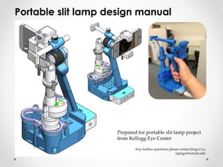
- 1. Portable slit lamp design manual Prepared for portable slit lamp project from Kellogg Eye Center Any further questions please contact Jingxi Lu, lujingxi@umich.edu
- 2. No. Part number Quantity Price Total price 1 base-bot 1 3DP 2 [NUT]M4X2.2MM_90695A035 3 $0.02 $0.06 3 topscrew-96016A117 1 $0.54 $0.54 4 eyebrow rest 1 3DP 5 4Xlens-8539T65 1 $14.56 $14.56 6 prismtower 1 3DP 7 object_cylinder 1 3DP 8 guideway 1 3DP 9 M3x90353A152 3 $0.06 $0.17 10 aperture-middle-width 1 3DP 11 aperture-bot-filter 1 3DP 12 flash light 1 $8.84 $8.84 13 M3.5X20CM_91800A193 2 $0.18 $0.37 14 aperture-top-length 1 3DP 15 slit_selector_cover-bot-1 1 3DP 16 slit_selector_cover-top 1 3DP 17 slit_selector_cover-bot-2 1 3DP 18 2-way-mirror 1 NA 19 M4X18MM_90116A215 4 $0.19 $0.78 20 battery 1 $25.99 $25.99 21 phoneclamp-left 1 3DP 22 clampphone-top 1 3DP 23 spring-94135K8 1 $1.19 $1.19 24 M5X100MM_92010A370 2 $1.31 $2.62 25 clampphone-bot 1 3DP 26 base-top 1 3DP 27 phoneclamp-right 1 3DP 28 M4X55CM_92005A242 1 $0.19 $0.19 29 Wingnut_M4_94300A310 1 $0.17 $0.17 30 M4X40CM_92005A236 1 $0.08 $0.08 31 7Xlens-8539T34 1 $14.56 $14.56 BOM for all parts
- 3. Smart device (iPhone, iTouch, Samsung etc.) Adjustable clamp Removable chinrest (optional) Battery Portable slit lamp for smart devices Optical system Base
- 4. Adjustable clamp • Suggested clamp width: 5-8 cm • The adjustable clamp adjusts both the vertical and horizontal axes of the smart device so its camera center axis can be aligned with the magnifier lens axis. • When using, clamp the smart device (phone) first and align its horizontal position, then untighten the wingnut a little bit to align its vertical position. At the end tighten the wingnut again to make sure the phone doesn’t drop. • When assembling the spring, fix one end first with M4 screw, then use a thin wire to pull the other end of spring to a point where another M4 screw can be inserted. Long bolts prevent clamp tilting (they are more robust than 3D printed plastic rods). Insert this cylinder into slit lamp base. Extension spring for clamping smart devices
- 5. Adjustable clamp: assembling procedures When assembling the spring, fix one end first with M4 screw, then use a thin wire to pull the other end of spring to a point where another M4 screw can be inserted. Pull with thin wireSmall opening below
- 6. Acrylic mirror Prism tower 7X magnifier lens (inside) Object cylinder Slit selector Flash light (inside) Two M3 slot screw, 20 mm Optical system: overall picture Two M4 cross screw, 18 mm Cut the acrylic mirror to desired size (9 x 14 mm) and sand polish the edges. Make sure it can be pressed into the prism tower tightly.
- 7. Optical system: assembling procedures 1* 2 3 4 5 6 7 8 9 10 11 12 13 14 • At 1st step use tape to fix these two parts temporary. Keep adjusting the height the of optical system to make sure the center of light beam is in the center view. • The guideway (purple part) is only shown in the 1st step. However it must be assembled first
- 8. Optical system: overall picture • Measured object distance: 64 mm, Image distance 80 mm. • Distance between camera and focus point: 89.5 mm • Focal length of 4X magnifier lens: 58.5 mm • > 8X total magnification ratio (4x from camera) Removable handle
- 9. Slit selector, discrete (current version) Length selector Width selector Filter selector The size of light beam is larger than that of slit itself. The ratio is about 1.25 (image distance/object distance = 80/64 = 1.25 ) . Based on this ratio the size of slit can be determined. Clean the thinnest slit with thin paper only! Make sure the gap between two pairs of slit selector are as close as possible (0.5~1mm is acceptable). Otherwise the light beam image may not have sharp edges.
- 10. Slit selector, continuous (optional version) Part name Description Quantity Price Total price flash light Ultrafire® Cree 7W 300LM Mini LED One Mode Flashlight 1 $8.84 $8.84 middleplate 2 3DP RACK Molded Nylon 14-1/2 Degree Angle Spur Gear, Rack, 48 Pitch, 1/8" Face Width, 1/8" Overall Height, 1' Long 4 $4.78 <$1 rackbase 2 3DP cover-bot 1 3DP cover-top 1 3DP Left GEAR Molded Nylon 14-1/2 Degree Angle Spur Gear, 48 Pitch, 20 Teeth, 0.417" Pitch Diameter, 1/8" Bore, 3/8” O’all length, 1/8” face width 2 $4.09 $8.18 Right GEAR Same as “Left GEAR” 2 $4.09 $8.18 90353A152 Metric Pan Head Slotted Machine Screw. Zinc- Plated Steel, M3 Size, 35mm Length, .5mm Pitch 4 $0.06 $0.23 90695A033 Class 04 Steel Thin Hex Nut - DIN 439B Zinc Plated, M3x0.5 Thread Size, 5.5mm Wide, 1.8mm High 4 $0.03 $0.12 All parts can be found in gearbox-subassembly.rar
- 11. Optical system: slit selector, continuous • Two pairs of gears & rack are used. Each pair of them is in charge of the adjustment of width or length. • Use M3 bolts as axes for gears can prevent axes break, which is a common failure mode when the axes were 3D printed. • Leave 0.25mm gap between frictional parts (such as gate and base) can prevent excessive friction force. Flash light Make sure the gap between two pairs of gates are as close as possible (1mm is acceptable). Otherwise the light beam image may not have sharp edges. The drawback of this design is the slit edges might not be parallel.
- 12. Base design • The handle should be removable so that the whole device is more portable • Make sure there is enough space between handle and slit box (about 100mm long, 15mm wide will be acceptable) • Add supporting ridge to make the handle stiffer • Openings for electric wires are necessary • Openings for adjustable chinrest subassembly
- 13. Electric components • The output voltage of batter is 5V, which is too high for the flash light. Potential failure modes due to high input voltage include: 1. at first the light intensity is very strong and flashlight becomes overheat 2. light becomes dim after a while 3. flashlight turns off automatically in 10 sec. The working voltage and current for the flashlight are about 1.5V and 200mA • Current solution for reducing the input voltage is to use 15 Ω resistor. However the disadvantages are: the input voltage on flashlight drops to 0.8 V, and the considerable amount of heat generated by resistors reduces the energy efficiency of the device quite significantly. • Another severe failure mode is the poor electric connection. Since the optical system moves all the time when using, if the wire pins hit any obstacles, the circuit breaks very easily. Need to solve this problem in the future.