Substituição ( 2sc1969 por erf 2030 ) na placa ept3600
•
2 j'aime•4,338 vues

Substituição ( 2sc1969 por erf 2030 ) na placa ept3600

Recommandé
Contenu connexe
Tendances
Tendances (20)
Similaire à Substituição ( 2sc1969 por erf 2030 ) na placa ept3600
Similaire à Substituição ( 2sc1969 por erf 2030 ) na placa ept3600 (20)
Dernier
Dernier (20)
Substituição ( 2sc1969 por erf 2030 ) na placa ept3600
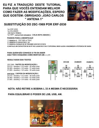
- 1. EPT360014B, EPT360014C MOSFET MOD http://www.cbtricks.com/ Modification Overview This mod package is for installing EKL Components ERF-2030 MOSFET as a final in a Galaxy DX Radios DX33HML, DX44V, DX55V, DX66, DX73V and other AM/FM 10 Meter Radios Manufactured by Ranger Communications Inc. (RCI) Using the EPT360014B, EPT360014C main Chassis. This MOD Package is base in the information from EKL Components Application Note AN-2030-1A Single Final Modification - Replaces 2SC1969 with ERF-2030 Required Parts: 1pc ERF-2030 1pc EN-369DR Thermal Grease 1pc 68Pf Ceramic Disc Capacitor (optional, see note Below.) Overview Of The Steps For Single Final Modification 1) Remove the 2SC1969 at TR43. 2) Remove capacitor at C167. 3) Remove the 22µH choke installed from location R215 to R216 (This is L35 see PCB layouts and schematic). 4) Install the ERF-2030 at TR43. Install ERF-2030 exactly the same way the 2SC1969 was installed, using all the SAME HARDWARE that was used with the 2SC1969. 5) Install the EN-369DR at TR43. Install this part on the solder side of the PCB. IMPORTANT: Do NOT stress the leads of the EN-369DR by bending them to aggressively. Bend the leads carefully and make sure that they are as short as possible. a) Solder the EN-369DR positive lead (marked +) to the gate pin of the ERF-2030 at TR43. b) Solder the EN-369DR negative lead (unmarked) to the source pin of the ERF-2030 at TR43. 6) Install a 68pF capacitor across C165 (this step is optional, but should help to maximize output power). Test posted in the CBTricks Forums 2SC1969: 25.615 - deadkey = 8.5 watts - 28 watts peak 26.965 - deadkey = 9.0 watts - 31 watts peak 27.865 - deadkey = 9.0 watts - 30 watts peak ERF2030: 25.615 - deadkey = 8.3 watts - 38 watts peak 26.965 - deadkey = 9.5 watts - 43 watts peak 27.865 - deadkey = 9.4 watts - 40 watts peak Notes: Peak power readings on IFR1200 Communications test set. No modulation limiters removed. Full modulation with no flat topping. Current draw same on both devices. 68pf cap not recommend (causes less output) Do not remove L33 slug (required to balance power on upper and lower bands.) ERF2030 has slight impedance mismatch on the output. (Not bad) SUBSTITUIÇÃO: 2SC -1969 POR ERF- 2030 PASSOS PARA A MODIFICAÇÃO VEJA NOTA ABAIXO }{ ( ) ( ) NOTA: NÃO RETIRE A BOBINA L 33 A MESMA É NECESSÁRIA PARA EQUILIBRAR O PODER DE LSB, USB, AM. EU FIZ A TRADUÇÃO DESTE TUTORIAL PARA QUE VOCÊS ENTENDAM MELHOR, A MODIFICAÇÃO, ESPERO QUE GOSTEM OBRIGADO: JOÃO CARLOS " ANTENA 1 " EU FIZ A TRADUÇÃO DESTE TUTORIAL PARA QUE VOCÊS ENTENDAM MELHOR COMO FAZER AS MODIFICAÇÕES, ESPERO QUE GOSTEM: OBRIGADO: JOÃO CARLOS " ANTENA 1" SUBSTITUIÇÃO DO 2SC-1969 POR ERF-2030 REMOVA O REMOVA O CAPACITOR C 167 CAPACITOR CERAMICO CHOQUE INSTALADO PROXIMOREMOVA CHOQUE DE RF PROXIMO AOS R215 E R216 INSTALE UM CAPACITOR DE 68PF NO LUGAR DO C165 É OPCIONAL MAIS AJUDARA A MAXIMIZAR A POTENCIA DE SAIDA 4) INSTALE UM CAPACITOR DE 68 PF NO LUGAR DO C165: É OPCIONAL MAIS AJUDA A MAXIMIZAR A POTENCIA DE SAIDA ANTES DA MODIFICAÇÃO ) DEPOIS DA MODIFICAÇÃO RESULTADOS DOS TESTES USE PASTA TÉRMICA PARA QUEM NÃO CONHECE O TR EN-369DR AQUI TEM O ESQUEMA COMO MONTAR UM------->>
- 2. EPT360014B, EPT360014C MOSFET MOD http://www.cbtricks.com/ Single Final Modification - Replaces 2SC1969 with ERF-2030 Step Fig # Description 1. 1 Remove the 2SC1969 at TR43, C167. 2. 1 Remove the 22µH choke installed from location R215 to R216 (This is L35 see PCB layouts and schematic). 3. 2 Remove C170 if installed in Radio. (This Capacitor may be installed or Not, If it is remove it, location on copper side (See Fig. 2). REMOVA O - REMOVA A REMOVA OS ESTE CAPACITOR PODE NÃO ESTAR INSTALADOSE ESTIVER INSTALADO C 170 SE TIVER ESTE CAPACITOR REMOVA O ( FIGURA 2 ) ANTENA 1
- 3. EPT360014B, EPT360014C MOSFET MOD http://www.cbtricks.com/ Step Fig # Description 3. 1 or 2 Install the ERF-2030 at TR43. Install ERF-2030 exactly the same way the 2SC1969 was installed, using all the SAME HARDWARE that was used with the 2SC1969. Don’t forget to apply thermal grease to the Transistor. 4. 2 Install the EN-369DR at TR43. Install this part on the solder side of the PCB. IMPORTANT: Do NOT stress the leads of the EN-369DR by bending them to aggressively. Bend the leads carefully and make sure that they are as short as possible. a. 2 a) Solder the EN-369DR positive lead (marked +) to the gate pin of the ERF-2030 at TR43. b. 2 Solder the EN-369DR negative lead (unmarked) to the source pin of the ERF-2030 at TR43. NÃO SE ESQUEÇA DE USAR A PASTA TÉRMICA não dobre os terminais do deixe os mais curtos possivel solde positivo na porta dosolde o lado positivo marcado com + INSTALE O ERF 2030 -TR43 EXATAMENTE COMO ESTA O 2SC 1969, NÃO SE ESQUEÇA DE USAR A PASTA TERMICA IMPORTANTE: NÃO DOBRE OS TERMINAIS DO EN-369DR , SE DOBRAREM DEIXE O MAIS CURTO O POSSIVEL. SOLDE O LADO MARCADO COM O SINAL DE + NA PORTA DO ERF 2030 TR45 ANTENA 1
- 4. EPT360014B, EPT360014C MOSFET MOD http://www.cbtricks.com/ ANTENA 1 EN-369DR ERF-2030