
Recommandé
Contenu connexe
Dernier
Dernier (20)
En vedette
En vedette (20)
Calibre Hardwire Install Guide
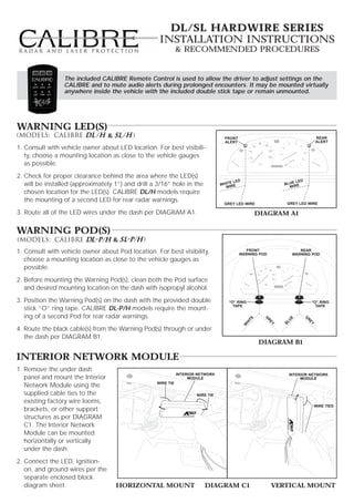
- 1. DL/SL HARDWIRE SERIES Installation Instructions & Recommended Procedures The included CALIBRE Remote Control is used to allow the driver to adjust settings on the CALIBRE and to mute audio alerts during prolonged encounters. It may be mounted virtually anywhere inside the vehicle with the included double stick tape or remain unmounted. Warning LED(s) & FRONT REAR ALERT ALERT 1. Consult with vehicle owner about LED location. For best visibili- ty, choose a mounting location as close to the vehicle gauges as possible. 2. Check for proper clearance behind the area where the LED(s) E LED LED will be installed (approximately 1”) and drill a 3/16” hole in the WHIT IRE BLUE E W WIR chosen location for the LED(s). CALIBRE DL/H models require the mounting of a second LED for rear radar warnings. GREY LED WIRE GREY LED WIRE 3. Route all of the LED wires under the dash per DIAGRAM A1. DIAGRAM A1 Warning Pod(s) & 1. Consult with vehicle owner about Pod location. For best visibility, FRONT WARNING POD REAR WARNING POD choose a mounting location as close to the vehicle gauges as possible. 2. Before mounting the Warning Pod(s), clean both the Pod surface and desired mounting location on the dash with isopropyl alcohol. 3. Position the Warning Pod(s) on the dash with the provided double “O” RING “O” RING TAPE TAPE stick “O” ring tape. CALIBRE DL-P/H models require the mount- ing of a second Pod for rear radar warnings. G UE TE G R R HI BL EY EY W 4. Route the black cable(s) from the Warning Pod(s) through or under the dash per DIAGRAM B1. DIAGRAM B1 Interior Network Module 1. Remove the under dash INTERIOR NETWORK INTERIOR NETWORK panel and mount the Interior MODULE MODULE WIRE TIE Network Module using the supplied cable ties to the WIRE TIE existing factory wire looms, WIRE TIES brackets, or other support structures as per DIAGRAM C1. The Interior Network Module can be mounted horizontally or vertically under the dash. 2. Connect the LED, ignition- on, and ground wires per the separate enclosed block diagram sheet. HORIZONTAL MOUNT DIAGRAM C1 VERTICAL MOUNT
- 2. Amplified Speaker 1. Route the amplified speaker cable around a panel edge and reattach the under dash panel per DIAGRAM D1. 2. For maximum audio output and concealment, DASH PANEL mount the amplified speaker to the outside of the SPEAKER under dash panel with the supplied screws per SPEAKER CABLE DIAGRAM D1. NOTE: If the vehicle is not equipped with an under SCREWS dash panel (e.g., Porsche), mount the ampli- fied speaker to existing factory wire looms, brackets, or support structures with the supplied cable ties. DIAGRAM D1 FRONT RADAR RECEIVER (ALL MODELS) NOTE: All radar receivers can be mounted behind plastic, rubber, or fiberglass up to 1/4” thick. Do not mount receivers behind metal, carbon fiber, or chromed plastic. 1. Choose a mounting location in the front of the vehicle that is not obstructed by any metal, carbon fiber, or chromed plastic. The radar receiver can be mounted horizontally or vertically, provided the arrows are point- ing forward, towards the road ahead. 2. Mount the radar receiver to the vehicle's structure using the supplied screws or wire tires (see diagram E1). RADAR RECEIVER SELF- TAPPING SCREWS RADAR RECEIVER METAL SELF- SUPPORT TAPPING SCREWS DIAGRAM E1 3. Connect the radar receiver to the 10’ black radar receiver cable. Align slot on cable plug to the notch on radar receiver socket, slide the locking ring forward over the socket, and turn ring clockwise 1/4 turn to engage safety lock (see diagram E2). 4. Route and affix the radar receiver cable along the inner fender in the engine compartment to the firewall using the provided wire straps. 5. Route the radar receiver cable through a factory rubber grommet on the firewall and into the passenger compartment (see diagram E3). Connect wires according to the separately enclosed block wiring diagram. LOCKING RIB FACTORY GROMMET LOCKING WINDOW LOCKING FRONT PIN RADAR RECEIVER CABLE LOCKING RING KEY BR GUIDE KEY WAY ITE OW GREEN LOCKING WH N PIN DIAGRAM E2 DIAGRAM E3
- 3. REAR RADAR RECEIVER (ALL MODELS) NOTE: All radar receivers can be mounted behind plastic, rubber, or fiberglass up to 1/4” thick. Do not mount behind metal, carbon fiber, or chromed plastic. 1. Choose a mounting location in the rear of the vehicle that is not obstructed by any metal, carbon fiber, or chromed plastic. The radar receiver can be mounted horizontally or vertically, provided the arrows are pointing to the rear, towards the road behind the vehicle. 2. Mount the radar receiver to the vehicle's structure using the sup- METAL SUPPORT plied screws or wire tires (see diagram F1). 3. Connect the radar receiver to the 25’ black radar receiver cable. RECEIVER Align slot on cable plug to the notch on radar receiver socket, SCREWS slide the locking ring forward over the socket, and turn ring clock- REAR RADAR RECEIVER (BEHIND BUMPER COVER) wise 1/4 turn to engage safety lock (see diagram F2). 4. Route the rear radar receiver cable into the trunk through a DIAGRAM F1 factory grommet. 5. If a factory grommet is not available, use the provided strain relief: LOCKING RIB a. Choose a location in the trunk compartment as close to the LOCKING WINDOW radar receiver as possible. LOCKING b. Drill a 1/2” hole into the chosen location for the strain relief. PIN LOCKING RING KEY GUIDE KEY WAY Do not drill into the trunk until you know LOCKING CAUTION! what is on both sides of the drilling area. PIN Watch for cables, spare tires, and gas tank. DIAGRAM F2 c. Install the strain relief and tighten the mounting nut securely (see diagram F3) ROUTE THROUGH VEHICLE d. Route the rear radar receiver cable through the strain relief, MOUNTING NUT leaving a little slack in the receiver cable. METAL TRUNK e. Tighten the waterproof gasket nut to create a water proof seal. WATERPROOF GASKET MATERIAL 6. Route the rear radar receiver cable through the trunk, into the TO RADAR DETECTOR passenger compartment along the driver's side, and under the dash. Connect wires according separately enclosed block DIAGRAM F3 wiring diagram. 44702 02/09