1. Printed by Jouve, 75001 PARIS (FR)
(19)EP2955447A1
TEPZZ 955447A_T
(11) EP 2 955 447 A1
(12) EUROPEAN PATENT APPLICATION
(43) Date of publication:
16.12.2015 Bulletin 2015/51
(21) Application number: 15166865.4
(22) Date of filing: 08.05.2015
(51) Int Cl.:
F23R 3/48 (2006.01)
F23R 3/60 (2006.01)
(84) Designated Contracting States:
AL AT BE BG CH CY CZ DE DK EE ES FI FR GB
GR HR HU IE IS IT LI LT LU LV MC MK MT NL NO
PL PT RO RS SE SI SK SM TR
Designated Extension States:
BA ME
Designated Validation States:
MA
(30) Priority: 13.06.2014 US 201462011732 P
(71) Applicant: Rolls-Royce Corporation
Indianapolis, Indiana 46225 (US)
(72) Inventors:
• Pinnick, Donald E.
Mooresville, IN Indiana 46158 (US)
• Sauer, Kevin M.
Plainfield, IN Indiana 46168 (US)
• Bennett, Russell N.
Indianapolis, IN Indiana 46205 (US)
• Lemke, Bradley A.
Avon, IN Indiana 46123 (US)
• Camara, Caleb
Indianapolis, IN Indiana 46260 (US)
• Hidlebaugh, Catherine
Naples, FL Florida 34109 (US)
• Dimon, Kathryn A.
Indianapolis, IN Indiana 46204 (US)
(74) Representative: Gille Hrabal
Brucknerstrasse 20
40593 Düsseldorf (DE)
(54) COMBUSTOR WITH SPRING-LOADED CROSSOVER TUBES
(57) Crossover tubes (10) for use with cans (12) of
a turbine engine. The crossover tubes (10) include an
outer member, an inner member that is adapted to move
collinearly with the outer member. The crossover tubes
(10) also include a pair of flanges and a biasing member
positioned between the flanges. The biasing member is
adapted to bias the flanges away from one another.
2. EP 2 955 447 A1
2
5
10
15
20
25
30
35
40
45
50
55
Description
[0001] This paper is a provisional patent application.
FIELD OF THE DISCLOSURE
[0002] The present disclosure relates to turbine en-
gines, and in particular to cans in turbine engines. More
particularly, the present disclosure relates to crossover
tubes that are used to interconnect the cans within the
turbine engine.
BACKGROUND
[0003] Gas turbine engines are used to power aircraft,
watercraft, power generators, pumps and the like. Gas
turbine engines typically include a compressor, a com-
bustor, and a turbine. The compressor compresses air
drawn into the engine and delivers high pressure air to
the combustor. The combustor is typically an assembly
that receives the high pressure air from the compressor
and adds fuel to the air which is burned to produce hot,
high-pressure gas. After burning the fuel, the hot, high-
pressuregas ispassed fromthecombustor to the turbine.
The turbine extracts work from the hot, high-pressure
gas to drive the compressor and residual energy is used
for propulsion or to drive an output shaft.
[0004] Certain combustor assemblies used in turbine
engines include a series of cans arranged around an axis
of engine rotation and interconnected by crossover tubes
that form passageways between the cans. Each can de-
fines a combustion chamber in which a fuel-air mixture
is burned. Burning fuel-air mixture passes through the
passageways formed by the crossover tubes to ignite the
fuel-air mixture in the adjacent cans.
SUMMARY
[0005] The present disclosure may comprise one or
more of the following features and combinations thereof.
[0006] According to one aspect of the present disclo-
sure, a combustor assembly for use with a turbine engine
may include a plurality of cans arranged in a circular pat-
tern and a plurality of crossover tube assemblies used
to interconnect the cans. Each can may define a com-
bustion chamber and may include at least two crossover
ports opening into the combustion chamber. The plurality
of crossover tube assemblies may interconnect the cans
at the location of the crossover ports.
[0007] In some embodiments, the crossover tube as-
semblies may each include a crossover tube provided
with an annular side wall having a pair of ends and an
annular flange that extends radially outwardly from the
annular sidewall. A portion of the annular sidewall may
be adapted to be positioned within the crossover port of
at least one can. The crossover tube assemblies may
each also include a biasing member positioned around
a portion the crossover tube and adapted to engage the
annular flange.
[0008] In some embodiments, the crossover tube may
include an outer member having the annular sidewall and
the flange coupled to one of the ends. The flange may
have first and second faces. The crossover tube may
also include an inner member having an annular sleeve
member, an annular sidewall and a second flange posi-
tioned between the annular sleeve member and the an-
nular sidewall of the inner member. The second flange
of the inner member may have first and second faces.
[0009] In some embodiments, the biasing member
may be positioned between the flanges. The inner mem-
ber may be configured to move collinearly with respect
to the outer member and the biasing member may be
adapted to bias the flanges away from each other.
[0010] In some embodiments, the annular sidewall of
the outer member has an inner diameter D1 and the an-
nular sleeve member of the inner member has an outer
diameter D3. The diameter D1 may be greater than the
diameter D3.
[0011] In some embodiments, the annular sidewall of
the inner member has an outer diameter D4. The diam-
eter D4 may be greater than diameter D3. The annular
sidewall of the outer member has an outer diameter D2
and the diameter D4 may be equal to diameter D2.
[0012] In some embodiments, the annular side wall of
the crossover tubes may form a passageway between
cans such that combustion gases travel from one can,
through the passageway of the crossover tube, and to a
second can. The biasing member may be located exter-
nal to the passageway such that combustion gasses
traveling through the passageway do not directly contact
the biasing member.
[0013] According to another aspect of the present dis-
closure, a crossover tube for use with a can of a turbine
engine is taught. The crossover tube may include an out-
er member and an inner member. The outer member
may have an annular sidewall with first and second ends
and a first flange coupled to one of the ends. The first
flange may have first and second faces. The inner mem-
ber may have an annular sleeve member, an annular
sidewall and a second flange positioned between the an-
nular sleeve member andtheannularsidewall oftheinner
member. The second flange of the inner member may
have first and second faces.
[0014] In some embodiments, the crossover tube may
include a biasing member. The biasing member may be
positioned around the annular sleeve member and be-
tween the first and second flanges. The biasing member
may be adapted to engage a face of the first and second
flanges. The inner member may be configured to move
collinearly with respect to the outer member and the bi-
asing member may be adapted to bias the first flange
away from the second flange.
[0015] In some embodiments, the annular sidewall of
the outer member has an inner diameter D1 and the an-
nular sleeve member of the inner member has an outer
diameter D3. The diameter D1 may be greater than the
1 2
3. EP 2 955 447 A1
3
5
10
15
20
25
30
35
40
45
50
55
diameter D3.
[0016] In some embodiments, the annular sidewall of
the inner member has an outer diameter D4. The diam-
eter D4 may be greater than diameter D3. The annular
sidewall of the outer member has an outer diameter D2
and the diameter D4 may be equal to diameter D2.
[0017] In some embodiments, the annular sleeve
member of the inner member may be adapted to slide
within the annular sidewall of the outer member. The bi-
asing member may be in the form of a wave spring that
is adapted to be positioned over the annular sleeve mem-
ber of the inner member of the crossover tube. The wave
spring may be adapted to engage the first and second
flanges.
[0018] According to another aspect of the present dis-
closure, a turbine engine may include a plurality of cans
and a plurality of crossover tubes. The plurality of cans
may be arranged in a circular pattern. Each can may
include at least two crossover ports that allow for the
ingress and egress of combustion gasses. The plurality
of crossover tubes may be adapted to be coupled to the
crossover ports to interconnect the cans. The crossover
tubes may include an annular side wall having a pair of
endsandanannular flange that extendsradially outward-
ly from the annular side wall. A portion of the annular
sidewall may be adapted to be positioned within the
crossover ports of adjacent cans.
[0019] In some embodiments, the crossover tubes
may each include a biasing member positioned around
a portion the annular side wall and adapted to engage
the annular flange. The crossover tubes may each in-
clude an outer member having an annular sidewall with
first and second ends and the flange coupled to one of
the ends. The flange may have first and second faces
[0020] In some embodiments, the crossover tubes
may each also include an inner member having an an-
nular sleeve member, an annular sidewall and a second
flange positioned between the annular sleeve member
and the annular sidewall of the inner member. The sec-
ond flange of the inner member may have first and sec-
ond faces. The biasing member may be positioned be-
tween the flanges
[0021] These and other features of the present disclo-
sure will become more apparent from the following de-
scription of the illustrative embodiments.
BRIEF DESCRIPTION OF THE DRAWINGS
[0022] The detailed description particularly refers to
the accompanying figures in which:
Fig. 1 is a perspective view of a turbine engine with
portions cut away to show that the engine includes
a can-type combustor assembly;
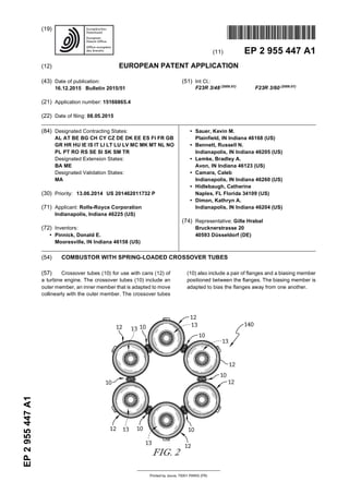
Fig. 2 is an end view of the can-type combustor as-
sembly showing six cans included in the combustor
arranged in a circular pattern with crossover tubes
positioned between and interconnecting the cans;
Fig. 3 is an enlarged view of two adjacent cans of
Fig. 2 showing a crossover tube interconnecting two
cans;
Fig 4 is a sectional view of Fig. 3 showing the cross-
over tube positioned between the cans;
Fig. 5 is a sectional view similar to the sectional view
of Fig. 4 showing movement of the right can with
respect to the left can and deflection of a biasing
member;
Fig. 6 is an exploded perspective view of another
embodiment of a crossover tube assembly;
Fig. 7 is an exploded side elevational view of the
crossover tube assembly of Fig. 6; and
Fig. 8 is a side elevational view of the crossover tube
assembly of Figs. 6 and 7 in the assembled position.
DETAILED DESCRIPTION
[0023] The arrangement of an illustrative combustor
assembly 140 in a gas turbine engine 110 is shown in
Fig. 1. The gas turbine engine 110 includes an output
shaft 120, a compressor 130, the combustor assembly
140, and a turbine 150. The output shaft 120 is driven by
the turbine 150 and may drive a propeller, a gearbox, a
pump, or the like (not shown) depending on the applica-
tion of the gas turbine engine 110. The compressor 130
compresses and delivers air to the combustor assembly
140. The combustor assembly 140 mixes fuel with the
compressed air received from the compressor 130 and
ignites the fuel. The hot, high pressure products of the
combustion reaction in the combustor assembly 140 are
directed into the turbine 150 and the turbine 150 extracts
work to drive the compressor 130 and the drive shaft 120.
[0024] The combustor assembly 140 is of the can-type
and includes a number of individual cans 12 and a
number of crossover tubes 10 as shown in Fig. 2. Each
can 12 defines a combustion chamber 13 in which a fuel-
air mixture is burned. Crossover tubes 10 of the present
disclosure are positioned between and are used to inter-
connect the combustion chambers 13 of cans 12 as sug-
gested, for example in Figs. 1 and 2. In the illustrative
embodiment, each crossover tube 10 includes a biasing
member 40 that accommodates movement of adjacent
cans 12 included in the same combustor assembly 140
during operation of a gas turbine engine 110.
[0025] Cans 12 are self-contained cylindrical combus-
tion chambers, as shown, for example, in Fig. 1. Each
can 12 typically includes a fuel nozzle 142 and a liner
144 mounted to a combustor casing 136. Some of the
cans 12 may include an igniter (not shown) used to ignite
the fuel atomized by the fuel nozzles 142. Fuel in cans
12 without igniters are ignited through the use of cross-
over tubes 10. For the purpose of initial ignition and con-
tinuous combustion, it has become customary to join the
interiors of adjacent cans 12 through crossover tubes 10,
so that when ignition occurs in one of the cans 12, a
burning fuel-air mixture will pass through the crossover
tubes 10 to ignite the fuel-air mixture in the adjacent cans
3 4
4. EP 2 955 447 A1
4
5
10
15
20
25
30
35
40
45
50
55
12.
[0026] Crossover tubes10 are adapted to interconnect
cans 12, as shown in Figs. 3 and 4. Cans 12 include a
cylindrical side wall 14 that is provided with openings 16
or ports formed by annular crossover ferrules 18. Cross-
over ferrules 18 include an annular sidewall 20 and an
annular flange 22 that is perpendicularly oriented to the
annular sidewall 20.
[0027] Annular sidewall 20 of crossover ferrule 18 is
coupled to the side wall 14 of the can 12 at a first end 24
and to annular flange 22 at a second end 26. Annular
sidewall 20 includes an inside surface 28 and an outside
surface 30 that is greater than the inside surface 28. In-
side surface 28 is positioned against a portion of cross-
over tube 10 when crossover tube 10 is positioned within
crossover ferrule 18 during assembly.
[0028] Annular flange 22 of crossover ferrules 18 are
relatively planar and include a first face 32 and an op-
posing second face 34. First face 32 faces towards can
12 and is coupled to annular sidewall 20. Second face
32 of annular flange 22 faces awayfrom can 12 and forms
an engagement surface for at least a portion of crossover
tubes 10. Second face 34 of annular flange 22 faces the
second face 34 of an annular flange 22 of an adjacent
can 12.
[0029] Crossover tube 10 includes an assembly of
components as shown, for example, in Fig. 6. Crossover
tube 10 includes an outer member 36, an inner member
38 that is telescopically received in outer member 36 and
a biasing member 40 positioned between outer and inner
members 36, 38.
[0030] Outer member 36 of crossover tube 10 includes
an annular side wall 42, as shown in Figs. 6 and 7. An-
nular side wall 42 includes a first end 44 and a spaced
apart second end 46. Annular side wall 42 also includes
an inside surface 48 and a spaced apart outer surface
50. Annular sidewall 42 has an inner diameter D1 and
an outer diameter D2 that is greater than inner diameter
D1.
[0031] Outer member 36 of crossover tube 10 also in-
cludes an annular flange 52 that is coupled to the second
end 46 of annular side wall 42. Annular flange 52 extends
radially outwardly from outer surface 50 of annular side
wall 42 and includes a first face 54 and a spaced apart
second face 56. Second face 56 of annular flange 52 is
adapted to engage biasing member 40 to provide a sup-
port surface for biasing member 40. Outer member 36
of crossover tube 10 is preferably machined as a single
pieceandpreferablymadefromahigh temperaturemetal
alloy such as a nickel based cobalt alloy or other alloys
that exhibit good high temperature and wear resistance.
[0032] Inner member 38 of crossover tube 10 is con-
figured to telescopingly engage outer member 36 and
both are adapted to move collinearly with respect to each
other. Inner member 38 includesan annular sleeve mem-
ber 58, an annular side wall 60 and an annular flange 62
positioned between sleeve member 58 and annular side
wall 60. Sleeve member 58 is adapted to be positioned
within annular side wall 42 of outer member 36.
[0033] Annular sleeve member 58 of inner member 38
is tubular in shape and includes a first end 63 and a
spaced apart second end 64, as shown in Figs. 6 and 7.
Sleeve member 58 includes an inner surface 66 and an
outer surface 68. Sleeve member 58 has an outer diam-
eter D3 that is less than diameter D1 of annular side wall
42 of outer member 36 to allow sleeve member 58 to fit
inside of annular side wall 42, as shown in Fig. 8. The
gap between outer surface 68 of sleeve member 58 and
inner surface 48 of annular side wall 42 is between .
001" and .004" and preferably between .001" and .002"
to permit linear movement between the two components,
while limiting unwanted blow by of combustion gasses.
[0034] Annular side wall 60 of inner member 38 in-
cludes a first end 70 and a spaced apart second end 72,
as shown in Fig. 7. Annular side wall 60 also includes an
inner surface 74 and an outer surface 76. Annular side
wall 60 has an outer diameter D4, which is greater than
outer diameter D3 of sleeve member 58. Outer diameter
D4 of annular side wall 60 is the same diameter as outer
diameter D2 of annular side wall 42. Annular side wall
60 is adapted to be inserted into crossover ferrule 18 of
can 12. Once inserted, outer surface 76 of annular side
wall 60 is positioned adjacent inside surface 28 of cross-
over ferrule 18.
[0035] Annular flange 62 of inner member 38 is posi-
tioned between annular side wall 60 and sleeve member
58, as shown in Fig. 7. Annular flange 62 is positioned
at second end 64 of sleeve member 58 and at first end
70 of annular side wall 60. Annular flange 62 of inner
member 38 includes a first face 78 and a spaced apart
second face80.First face78of inner member 38isadapt-
ed to face second face 56 of annular flange 52 of outer
member 36. Inner member 36 of crossover tube 10 is
preferably machined as a single piece and preferably
made from a high temperature alloy such as a nickel
based cobalt alloy or other alloys that exhibit good high
temperature and wear resistance.
[0036] Biasing member 40 is designed to allow for
movement between inner member 38 and outer member
36 and maintains force against flanges 52, 62 to secure
flanges 52, 62 against crossover ferrules 18. Biasing
member 40 is in the form of a compression spring such
as a coil spring and is preferably a single turn wave spring
or a nested wave spring.
[0037] A wave spring, also known as a coiled wave
spring, a disc spring, or a scrowave spring, is a spring
made from pre-hardened flat wire in a process called,
on-edge-coiling, also known as edge winding. During this
process, waves are added to give it a spring effect. The
number of turns and waves can be adjusted to accom-
modate stronger force.
[0038] A wave spring has the following advantages
over a traditional coiled spring or a washer. The axial
space can be reduced by 50% versus a coil spring. As a
result, an overall size of the crossover tube assembly
becomes smaller and thus significant weight reduction.
5 6
5. EP 2 955 447 A1
5
5
10
15
20
25
30
35
40
45
50
55
Further, the load in an axial direction is 100% transfera-
ble.
[0039] Use of a wave spring as a biasing member al-
lows the crossover tube assembly 10 to accommodate
higher thrust load within the limited axial space as only
elements such as the size of the wire, the number of
waves, theheight of waves, and thenumber of turnsneed
to be adjusted to accommodate such high thrust loads.
Biasing member 40 is preferably made from a nickel
based alloy or a stainless alloy for heat resistance. Lo-
cation of biasing member 40 with respect to outer and
inner members 36, 38 protect biasing member 40 from
hot combustion gasses. The reduction in heat exposure
significantly increases the life of biasing member 40 and
reduces metal fatigue.
[0040] In another embodiment, crossover tube 81 can
be a one piece design, as shown in Figs. 3-5, as opposed
to the two piece design shown in Figs. 6-8, which include
outer and inner members 36, 38. In this embodiment,
crossover tube 10 includes a first annular side wall sec-
tion 82, a second annular side wall section 84 and an
annular flange 86. First annular side wall section 82 is
shorter in axial length than second annular side wall sec-
tion 84 so that annular flange 86 is closer to first end 88
than to second end 90.
[0041] Annular flange 86of crossover tube81, includes
a first face 92 and a spaced apart second face 94. When
assembled with can 12, first annular side wall section 82
is positioned within a first ferrule 18 of a first can 12 and
second annular side wall section 84 is positioned within
a second ferrule 18 of a second can 12, as shown, for
example in Figs. 3-5. Movement of the first can 12 and
ferrule 18 toward the second can 12 and ferrule 18 caus-
es movement of the second annular side wall section 84
with respect to the ferrule 18 and compression of biasing
member 40, as shown in Fig. 5.
[0042] Both crossover tube designs 10, 81 make as-
sembling the cans 12 easier. This is because biasing
member 40 of crossover tube compensates for errors in
manufacturing tolerances in the cans 12 and ferrules 18
so that spacer washers do not need to be used to take
up any unwanted gaps between annular flanges 22 of
adjacent ferrules18. Also, duringoperationof the engine,
heat expansion of the metal and vibration caused by en-
gine operation is absorbed by the crossover tubes and
biasing member 40, which reduces wear to cans 12 and
ferrules 18. The crossover tube design also controls air-
flow leakage at the crossover interface between cans 12.
[0043] While the disclosure has been illustrated and
described in detail in the foregoing drawings and descrip-
tion, the same is to be considered as exemplary and not
restrictive in character, it being understood that only il-
lustrative embodiments thereof have been shown and
described and that all changes and modifications that
come within the spirit of the disclosure are desired to be
protected.
Claims
1. A combustor assembly (140) for use with a turbine
engine (110), the combustor assembly (140) com-
prising:
a plurality of cans (12) arranged in a circular pat-
tern, each can (12) defining a combustion cham-
ber (13) and including at least two crossover
ports opening (16) into the combustion chamber
(13);
a plurality of crossover tube assemblies used to
interconnect the cans (12) at the location of the
crossover ports (16), the crossover tube assem-
blies each including a crossover tube (10) pro-
vided with an annular side wall (20, 42, 60) hav-
ing a pair of ends (24, 26, 44, 46, 70, 72) and
an annular flange (22, 52, 62) that extends ra-
dially outwardly from the annular sidewall (20,
42, 60), a portion of the annular sidewall (20, 42,
60) is adapted to be positioned within the cross-
over port (16) of at least one can (12); and
the crossover tube assemblies each also includ-
ing a biasing member (40) positioned around a
portion of the crossover tube (10) and adapted
to engage the annular flange (22, 52, 62).
2. The combustor assembly (140) of claim 1, wherein
the crossover tube (10) includes an outer member
(36) having the annular sidewall (42) and the flange
(52) coupled to one of the ends (44, 46), the flange
(52) having first and second faces (54, 56).
3. The combustor assembly (140) of claim 1 or 2,
wherein the crossover tube (10) also includes an in-
ner member (38) having an annular sleeve member
(58), an annular sidewall (60) and a second flange
(62) positioned between the annular sleeve member
(58) and the annular sidewall (60) of the inner mem-
ber (38); the second flange (62) of the inner member
(38) having first and second faces (78, 80).
4. The combustor assembly (140) of claim 3, wherein
the biasing member (40) is positioned between the
flanges (52, 62).
5. The combustor assembly (140) of claim 3 or 4,
wherein the inner member (38) is configured to move
collinearly with respect to the outer member (36) and
the biasing member (40) is adapted to bias the flang-
es (52, 62) away from each other.
6. The combustor assembly (140) of claim 3, 4 or 5,
wherein the annular sidewall (42) of the outer mem-
ber (36) has an inner diameter D1, and the annular
sleeve member (58) of the inner member (38) has
an outer diameter D3, wherein the diameter D1 is
greater than the diameter D3.
7 8
6. EP 2 955 447 A1
6
5
10
15
20
25
30
35
40
45
50
55
7. The combustor assembly (140) of claim 6, wherein
the annular sidewall (60) of the inner member (38)
has an outer diameter D4, wherein the diameter D4
is greater than diameter D3.
8. The combustor assembly (140) of claim 7, wherein
the annular sidewall (42) of the outer member (36)
has an outer diameter D2, wherein diameter D4 is
equal to diameter D2.
9. The combustor assembly (140) of one of the preced-
ing claims, wherein the annular side wall (20, 42, 60)
of the crossover tubes (10) forms a passageway be-
tween cans (12) such that combustion gases travel
from one can (12), through the passageway of the
crossover tube (10) and to a second can (12).
10. The combustor of claim 9, wherein the biasing mem-
ber (40) is located external to the passageway such
that combustion gasses traveling through the pas-
sageway do not directly contact the biasing member
(40).
11. The combustor assembly (140) of one of the preced-
ing claims 3 to 10, wherein the crossover tube (10),
wherein
the biasing member (40) is positioned around the
annular sleeve member (58) andthebiasingmember
(40) is adapted to engage a face (56, 78) of the first
and second flanges (52, 62).
12. A combustor assembly (140) of one of the preceding
claims 3 to 11, wherein the annular sleeve member
(58) of the inner member (38) is adapted to slide
within the annular sidewall (42) of the outer member
(36).
13. A combustor assembly (140) of one of the preceding
claims 3 to 12, wherein the biasing member (40) is
in the form of a wave spring that is adapted to be
positioned over the annular sleeve member (58) of
the inner member (38) of the crossover tube (10),
the wave spring adapted to engage the first and sec-
ond flanges (52, 62).
14. A combustor assembly (140) of one of the preceding
claims,
wherein
each can (12) includes at least two crossover ports
(16) that allow for the ingress and egress of combus-
tion gasses;
the plurality of crossover tubes (10) are adapted to
be coupled to the crossover ports (16) to intercon-
nect the cans (12); and
the biasing member (40) is positioned around a por-
tion of the annular side wall (20, 42, 60).
15. A crossover tube for use with a can of a turbine en-
gine with a combustor assembly (140) of one of the
preceding claims comprising:
an outer member (36) having an annular side-
wall (42) with first and second ends (44, 46) and
a first flange (52) coupled to one of the ends (44,
46), the first flange (52) having first and second
faces (54, 56);
an inner member (38) having an annular sleeve
member (58), an annular sidewall (60) and a
second flange (62) positioned between the an-
nular sleeve member (58) and the annular side-
wall (60) of the inner member (38); the second
flange (62) of the inner member (38) having first
and second faces (78, 80);
a biasing member (40) positioned around the
annular sleeve member (58) and between the
first and second flanges (52, 62), the biasing
member (40) adapted to engage a face (56, 78)
of the first and second flanges (52, 62); and
wherein the inner member (38) is configured to
move collinearly with respect to the outer mem-
ber (36) and the biasing member (40) is adapted
to bias the first flange (52) away from the second
flange (62).
9 10
![EP 2 955 447 A1
2
5
10
15
20
25
30
35
40
45
50
55
Description
[0001] This paper is a provisional patent application.
FIELD OF THE DISCLOSURE
[0002] The present disclosure relates to turbine en-
gines, and in particular to cans in turbine engines. More
particularly, the present disclosure relates to crossover
tubes that are used to interconnect the cans within the
turbine engine.
BACKGROUND
[0003] Gas turbine engines are used to power aircraft,
watercraft, power generators, pumps and the like. Gas
turbine engines typically include a compressor, a com-
bustor, and a turbine. The compressor compresses air
drawn into the engine and delivers high pressure air to
the combustor. The combustor is typically an assembly
that receives the high pressure air from the compressor
and adds fuel to the air which is burned to produce hot,
high-pressure gas. After burning the fuel, the hot, high-
pressuregas ispassed fromthecombustor to the turbine.
The turbine extracts work from the hot, high-pressure
gas to drive the compressor and residual energy is used
for propulsion or to drive an output shaft.
[0004] Certain combustor assemblies used in turbine
engines include a series of cans arranged around an axis
of engine rotation and interconnected by crossover tubes
that form passageways between the cans. Each can de-
fines a combustion chamber in which a fuel-air mixture
is burned. Burning fuel-air mixture passes through the
passageways formed by the crossover tubes to ignite the
fuel-air mixture in the adjacent cans.
SUMMARY
[0005] The present disclosure may comprise one or
more of the following features and combinations thereof.
[0006] According to one aspect of the present disclo-
sure, a combustor assembly for use with a turbine engine
may include a plurality of cans arranged in a circular pat-
tern and a plurality of crossover tube assemblies used
to interconnect the cans. Each can may define a com-
bustion chamber and may include at least two crossover
ports opening into the combustion chamber. The plurality
of crossover tube assemblies may interconnect the cans
at the location of the crossover ports.
[0007] In some embodiments, the crossover tube as-
semblies may each include a crossover tube provided
with an annular side wall having a pair of ends and an
annular flange that extends radially outwardly from the
annular sidewall. A portion of the annular sidewall may
be adapted to be positioned within the crossover port of
at least one can. The crossover tube assemblies may
each also include a biasing member positioned around
a portion the crossover tube and adapted to engage the
annular flange.
[0008] In some embodiments, the crossover tube may
include an outer member having the annular sidewall and
the flange coupled to one of the ends. The flange may
have first and second faces. The crossover tube may
also include an inner member having an annular sleeve
member, an annular sidewall and a second flange posi-
tioned between the annular sleeve member and the an-
nular sidewall of the inner member. The second flange
of the inner member may have first and second faces.
[0009] In some embodiments, the biasing member
may be positioned between the flanges. The inner mem-
ber may be configured to move collinearly with respect
to the outer member and the biasing member may be
adapted to bias the flanges away from each other.
[0010] In some embodiments, the annular sidewall of
the outer member has an inner diameter D1 and the an-
nular sleeve member of the inner member has an outer
diameter D3. The diameter D1 may be greater than the
diameter D3.
[0011] In some embodiments, the annular sidewall of
the inner member has an outer diameter D4. The diam-
eter D4 may be greater than diameter D3. The annular
sidewall of the outer member has an outer diameter D2
and the diameter D4 may be equal to diameter D2.
[0012] In some embodiments, the annular side wall of
the crossover tubes may form a passageway between
cans such that combustion gases travel from one can,
through the passageway of the crossover tube, and to a
second can. The biasing member may be located exter-
nal to the passageway such that combustion gasses
traveling through the passageway do not directly contact
the biasing member.
[0013] According to another aspect of the present dis-
closure, a crossover tube for use with a can of a turbine
engine is taught. The crossover tube may include an out-
er member and an inner member. The outer member
may have an annular sidewall with first and second ends
and a first flange coupled to one of the ends. The first
flange may have first and second faces. The inner mem-
ber may have an annular sleeve member, an annular
sidewall and a second flange positioned between the an-
nular sleeve member andtheannularsidewall oftheinner
member. The second flange of the inner member may
have first and second faces.
[0014] In some embodiments, the crossover tube may
include a biasing member. The biasing member may be
positioned around the annular sleeve member and be-
tween the first and second flanges. The biasing member
may be adapted to engage a face of the first and second
flanges. The inner member may be configured to move
collinearly with respect to the outer member and the bi-
asing member may be adapted to bias the first flange
away from the second flange.
[0015] In some embodiments, the annular sidewall of
the outer member has an inner diameter D1 and the an-
nular sleeve member of the inner member has an outer
diameter D3. The diameter D1 may be greater than the
1 2](data:image/gif;base64,R0lGODlhAQABAIAAAAAAAP///yH5BAEAAAAALAAAAAABAAEAAAIBRAA7)