Experiment No.5 Flow Over Weirs in a Flume-ROSAROS.pdf
1. UNIVERSITY OF THE EAST
COLLEGE OF ENGINEERING
CIVIL ENGINEERING DEPARTMENT
NAME: ROSAROS, KENT ARNEL T. GRADE:
SUBJECT & SECTION: NCE 3206-CE2
EXPERIMENT NO. 5
FLOW OVER WEIRS IN A FLUME
I. OBJECTIVES:
1. To become familiar with a teaching flume, its use and its components.
2. To determine the characteristics of flow over a sharp-crested weir and a trapezoidal weir.
3. To determine the relationship between upstream head and flowrate for water flowing a
sharp crested weir and a trapezoidal weir.
4. To calculate the discharge coefficient and to observe the flow patterns obtained.
II. MATERIALS/INSTRUMENTS:
Hydraulic Bench
Teaching Flume
Sharp-crested Weir
Trapezoidal Weir
Vernier Level Gauge
III. THEORY
A notch is an opening in the side of a measuring tank or reservoir extending above the free
surface. These notches are used to measure discharge of open channel flows, by passing or
placing or constructing them across the stream. Notches are generally used for measuring
discharge in small open channels or laboratory flumes.
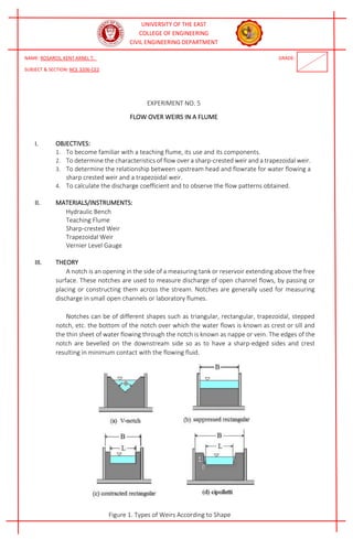
Notches can be of different shapes such as triangular, rectangular, trapezoidal, stepped
notch, etc. the bottom of the notch over which the water flows is known as crest or sill and
the thin sheet of water flowing through the notch is known as nappe or vein. The edges of the
notch are bevelled on the downstream side so as to have a sharp-edged sides and crest
resulting in minimum contact with the flowing fluid.
Figure 1. Types of Weirs According to Shape
2. UNIVERSITY OF THE EAST
COLLEGE OF ENGINEERING
CIVIL ENGINEERING DEPARTMENT
The discharge over notch is measured by measuring the head acting over the notch. As
water approaches the notch, its surface becomes curved. Therefore, the head over the notch
is to be measured at the upstream of the notch where the effect of curvature is minimum.
Also, it should be close to the notch so that the loss of energy between head measuring section
and notch is negligible. In practical, the head over notch is measured at a distance of 3 to 4
times the maximum head from the notch.
Figure 2. Cross-Section of a Rectangular Weir
Figure 3. Longitudinal Section of a Rectangular Weir
Figure 4. Trapezoidal Weir
3. UNIVERSITY OF THE EAST
COLLEGE OF ENGINEERING
CIVIL ENGINEERING DEPARTMENT
IV. PROCEDURE
A. Flow over a Sharp-crested Weir
1. Ensure the flume is level, with no stop logs installed at the discharge end of the
channel.
2. Measure and record the actual width “b” of the sharp crested rectangular weir.
3. Install the weir in the flume with the sharp edge upstream. Ensure that the weir is
secured with its bottom at the bed of the flume.
4. The datum for all the measurements will be the top edge of the weir plate. Carefully
adjust the level gauge to coincide with the top of the weir, taking care not to
damage the edge of the weir then record the datum reading as ho.
5. Alternatively, to avoid damages to the weir, open the flow control valve and admit
water into the channel until it discharges over the weir then close the flow control
valve to stop the flow of water. When the water stops flowing over the weir adjust
the level gauge to coincide with the surface of the water and record the datum
reading as ho.
6. Open the flow control valve and set to 50 L/min.
7. Allow a steady flow to develop before taking a reading. Record this as hf.
8. Adjust the flow control valve to three more different flow rates. Note that the flow
rates must be set so as not to fully submerged the weir, that is, the downstream must
remain unsubmerged.
9. Tabulate the result in Table A1.
B. Flow over a Trapezoidal Weir
1. Measure the properties of the trapezoidal weir.
2. Repeat the steps using the trapezoidal weir and tabulate the data in Table A2.
3. Note that the flow rates must be set so as not to submerge the upstream and
downstream of the trapezoidal weir.
V. DATA AND RESULTS
Table A1. Sharp Crested Weir, b = _0.085_ m
No.
Qa
(L/min)
Qa
(m3/s)
hf
(m)
ho
(m)
H = hf- ho
(m)
Qth
(m3/s) Cd=Qa/Qth
1 50 0.000833 0.16 0.13 0.03 1.304X10⁻³
0.64
2 100 0.00167 0.179 0.13 0.049 2.723X10⁻³
0.6134
3 150 0.0025 0.191 0.13 0.061 3.782X10⁻³
0.6611
4 170 0.00283 0.20 0.13 0.07 4.649X10⁻³
0.6088
Average Cd 0.6299
Table A2. Trapezoidal Weir, bbot =0.045 m, btop= 0.07 m, = 14.04 deg from the vertical
No.
Qa
(L/min)
Qa
(m3/s)
hf
(m)
ho
(m)
H = hf- ho
(m)
Qth
(m3/s) Cd=Qa/Qth
1 50 0.000833 0.127 0.085 0.042 1.144X10⁻³
0.7281
2 55 0.000917 0.129 0.085 0.044 1.226X10⁻³
0.748
3 60 0.001 0.131 0.085 0.046 1.311X10⁻³
0.7628
4 65 0.0011 0.134 0.085 0.049 1.441X10⁻³
0.7633
Average Cd 0.7506
4. UNIVERSITY OF THE EAST
COLLEGE OF ENGINEERING
CIVIL ENGINEERING DEPARTMENT
VI. COMPUTATIONS
5. UNIVERSITY OF THE EAST
COLLEGE OF ENGINEERING
CIVIL ENGINEERING DEPARTMENT
6. UNIVERSITY OF THE EAST
COLLEGE OF ENGINEERING
CIVIL ENGINEERING DEPARTMENT
7. UNIVERSITY OF THE EAST
COLLEGE OF ENGINEERING
CIVIL ENGINEERING DEPARTMENT
VII. ILLUSTRATION / SET UP OF THE EXPERIMENT
VIII. OBSERVATION AND CONCLUSION
8. UNIVERSITY OF THE EAST
COLLEGE OF ENGINEERING
CIVIL ENGINEERING DEPARTMENT
IX. DOCUMENTATION
9. UNIVERSITY OF THE EAST
COLLEGE OF ENGINEERING
CIVIL ENGINEERING DEPARTMENT
10. UNIVERSITY OF THE EAST
COLLEGE OF ENGINEERING
CIVIL ENGINEERING DEPARTMENT
11. UNIVERSITY OF THE EAST
COLLEGE OF ENGINEERING
CIVIL ENGINEERING DEPARTMENT
12. UNIVERSITY OF THE EAST
COLLEGE OF ENGINEERING
CIVIL ENGINEERING DEPARTMENT
13. UNIVERSITY OF THE EAST
COLLEGE OF ENGINEERING
CIVIL ENGINEERING DEPARTMENT
14. UNIVERSITY OF THE EAST
COLLEGE OF ENGINEERING
CIVIL ENGINEERING DEPARTMENT
15. UNIVERSITY OF THE EAST
COLLEGE OF ENGINEERING
CIVIL ENGINEERING DEPARTMENT