SlideShare une entreprise Scribd logo
1  sur  117
Télécharger pour lire hors ligne
www.dienhathe.vn
www.dienhathe.com
Thank you for purchasing LS Variable Frequency Drives!
SAFETY INSTRUCTIONS
Always follow safety instructions to prevent accidents and potential hazards from occurring.
In this manual, safety messages are classified as follows:
WARNING
CAUTION
Throughout this manual we use the following two illustrations to make you aware of safety
considerations:
Identifies potential hazards under certain conditions.
Read the message and follow the instructions carefully.
Identifies shock hazards under certain conditions.
Particular attention should be directed because dangerous voltage may be present.
Keep operating instructions handy for quick reference.
Read this manual carefully to maximize the performance of SV-iG5 series inverter and ensure its
safe use.
WARNING
Do not remove the cover while power is applied or the unit is in operation.
Otherwise, electric shock could occur.
Do not run the inverter with the front cover removed.
Otherwise, you may get an electric shock due to high voltage terminals or charged capacitor
exposure.
Do not remove the cover except for periodic inspections or wiring, even if
the input power is not applied.
Otherwise, you may access the charged circuits and get an electric shock.
Wiring and periodic inspections should be performed at least 10 minutes
after disconnecting the input power and after checking the DC link voltage
Improper operation may result in slight to medium personal injury
or property damage.
Improper operation may result in serious personal injury or death.
www.dienhathe.vn
www.dienhathe.com
is discharged with a meter (below DC 30V).
Otherwise, you may get an electric shock.
Operate the switches with dry hands.
Otherwise, you may get an electric shock.
Do not use the cable when its insulating tube is damaged.
Otherwise, you may get an electric shock.
Do not subject the cables to scratches, excessive stress, heavy loads or
pinching.
Otherwise, you may get an electric shock.
CAUTION
Install the inverter on a non-flammable surface. Do not place flammable
material nearby.
Otherwise, fire could occur.
Disconnect the input power if the inverter gets damaged.
Otherwise, it could result in a secondary accident and fire.
After the input power is applied or removed, the inverter will remain hot for
a couple of minutes.
Otherwise, you may get bodily injuries such as skin-burn or damage.
Do not apply power to a damaged inverter or to an inverter with parts
missing even if the installation is complete.
Otherwise, electric shock could occur.
Do not allow lint, paper, wood chips, dust, metallic chips or other foreign
matter into the drive.
Otherwise, fire or accident could occur.
OPERATING PRECAUTIONS
(1) Handling and installation
Handle according to the weight of the product.
Do not stack the inverter boxes higher than the number recommended.
Install according to instructions specified in this manual.
Do not open the cover during delivery.
www.dienhathe.vn
www.dienhathe.com
Do not place heavy items on the inverter.
Check the inverter mounting orientation is correct.
Do not drop the inverter, or subject it to impact.
Follow your national electrical code for grounding. Recommended Ground impedance for
200 V Class is below 100 ohm and for 400V class is below 10 ohm.
iG5 series contains ESD (Electrostatic Discharge) sensitive parts. Take protective
measures against ESD (Electrostatic Discharge) before touching the pcb for inspection or
installation.
Use the inverter under the following environmental conditions:
Ambient
temperature
- 10 ~ 40 ℃ (non-freezing)
Relative
humidity
90% RH or less (non-condensing)
Storage
temperature
- 20 ~ 65 ℃
Location
Protected from corrosive gas, combustible gas, oil mist
or dust
Altitude,
Vibration
Max. 1,000m above sea level, Max. 5.9m/sec2
(0.6G)
or less
Environment
Atmospheric
pressure
70 ~ 106 kPa
(2) Wiring
Do not connect a power factor correction capacitor, surge suppressor, or RFI filter to the
output of the inverter.
The connection orientation of the output cables U, V, W to the motor will affect the
direction of rotation of the motor.
Incorrect terminal wiring could result in the equipment damage.
Reversing the polarity (+/-) of the terminals could damage the inverter.
Only authorized personnel familiar with LG inverter should perform wiring and inspections.
Always install the inverter before wiring. Otherwise, you may get an electric shock or have
bodily injury.
(3) Trial run
Check all parameters during operation. Changing parameter values might be required
depending on the load.
Always apply permissible range of voltage to the each terminal as indicated in this manual.
Otherwise, it could lead to inverter damage.
(4) Operation precautions
When the Auto restart function is selected, stay away from the equipment as a motor will
restart suddenly after an alarm stop.
www.dienhathe.vn
www.dienhathe.com
The Stop key on the keypad is valid only when the appropriate function setting has been
made. Prepare an emergency stop switch separately.
If an alarm reset is made with the reference signal present, a sudden start will occur.
Check that the reference signal is turned off in advance. Otherwise an accident could
occur.
Do not modify or alter anything inside the inverter.
Motor might not be protected by electronic thermal function of inverter.
Do not use a magnetic contactor on the inverter input for frequent starting/stopping of the
inverter.
Use a noise filter to reduce the effect of electromagnetic interference. Otherwise nearby
electronic equipment may be affected.
In case of input voltage unbalance, install AC reactor. Power Factor capacitors and
generators may become overheated and damaged due to potential high frequency noise
transmitted from inverter.
Use an insulation-rectified motor or take measures to suppress the micro surge voltage
when driving 400V class motor with inverter. A micro surge voltage attributable to wiring
constant is generated at motor terminals, and may deteriorate insulation and damage
motor.
Before operating unit and prior to user programming, reset user parameters to default
settings.
Inverter can easily be set to high-speed operations, Verify capability of motor or machinery
prior to operating unit.
Stopping torque is not produced when using the DC-Break function. Install separate
equipment when stopping torque is needed.
(5) Fault prevention precautions
Provide a safety backup such as an emergency brake which will prevent the machine and
equipment from hazardous conditions if the inverter fails.
(6) Maintenance, inspection and parts replacement
Do not conduct a megger (insulation resistance) test on the control circuit of the inverter.
Refer to Chapter 6 for periodic inspection (parts replacement).
(7) Disposal
Handle the inverter as an industrial waste when disposing of it.
(8) General instructions
Many of the diagrams and drawings in this instruction manual show the inverter without a
circuit breaker, a cover or partially open. Never run the inverter like this. Always place the
cover with circuit breakers and follow this instruction manual when operating the inverter.
www.dienhathe.vn
www.dienhathe.com
1
CONTENTS
USER SELECTION GUIDE (IG5 SPECIFICATIONS)..................................................................3
CHAPTER 1 - INSTALLATION .................................................................................................5
1.1 Inspection ............................................................................................................................................. 5
1.2 Environmental Conditions .................................................................................................................... 5
1.3 Mounting............................................................................................................................................... 5
1.4 Other Precautions................................................................................................................................ 6
1.5 Dimensions .......................................................................................................................................... 7
1.6 Basic Wiring ......................................................................................................................................... 8
1.7 Power Terminals .................................................................................................................................. 9
1.8 Control Terminals............................................................................................................................... 12
CHAPTER 2 - OPERATION ....................................................................................................15
2.1 Keypad and Parameter Group Setting .............................................................................................. 15
2.2 Parameter Setting and Change ......................................................................................................... 16
2.3 Parameter Group................................................................................................................................ 18
2.4 Operation............................................................................................................................................ 21
CHAPTER 3 - PARAMETER LIST ..........................................................................................23
3.1 Drive Group [DRV] ............................................................................................................................. 23
3.2 Function Group 1 [FU1]...................................................................................................................... 24
3.3 Function Group 2 [FU2]...................................................................................................................... 26
3.4 Input/Output Group [I/O] .................................................................................................................... 29
CHAPTER 4 - PARAMETER DESCRIPTION .........................................................................33
4.1 Drive Group [DRV] ............................................................................................................................. 33
4.2 Function 1 Group [FU1]...................................................................................................................... 38
4.3 Function 2 Group [FU2]...................................................................................................................... 49
4.4 Input/Output Group [I/O] .................................................................................................................... 61
CHAPTER 5 - MODBUS-RTU COMMUNICATION.................................................................73
5.1 Introduction......................................................................................................................................... 73
5.2 Specifications ..................................................................................................................................... 73
5.3 Installation .......................................................................................................................................... 74
5.4 Operating............................................................................................................................................ 75
5.5 Communication Protocol (Modbus-RTU)........................................................................................... 75
5.6 Communication Protocol (LS-BUS ASCII)......................................................................................... 76
5.7 Parameter Code List .......................................................................................................................... 80
5.8 Troubleshooting.................................................................................................................................. 86
5.9 ASCII Code List.................................................................................................................................. 88
www.dienhathe.vn
www.dienhathe.com
2
CHAPTER 6 - TROUBLESHOOTING & MAINTENANCE ......................................................89
6.1 Fault Display ...................................................................................................................................... 89
6.2 Fault (Inverter Fault) Reset................................................................................................................ 91
6.3 Fault Remedy..................................................................................................................................... 92
6.4 Troubleshooting ................................................................................................................................. 93
6.5 How to Check Power Components.................................................................................................... 94
6.6 Maintenance....................................................................................................................................... 95
6.7 Daily and Periodic Inspection Items .................................................................................................. 96
CHAPTER 7 - OPTIONS..........................................................................................................99
7.1 Braking Resistor................................................................................................................................. 99
7.2 DIN Rail Base................................................................................................................................... 101
7.3 Remote Cable .................................................................................................................................. 102
7.4 NEMA option.................................................................................................................................... 102
APPENDIX A - FUNCTIONS BASED ON THE USE................................................................103
APPENDIX B- PERIPHERAL DEVICES ..................................................................................104
DECLARATION OF CONFORMITY.........................................................................................105
www.dienhathe.vn
www.dienhathe.com
3
USER SELECTION GUIDE (IG5 SPECIFICATIONS)
230V Class (0.5~5.4HP)
Inverter Type
(SVxxxiG5-x)
004-1 008-1 015-1 004-2 008-2 015-2 022-2 037-2 040-2
HP 0.5 1 2 0.5 1 2 3 5 5.4Motor
Rating1
kW 0.37 0.75 1.5 0.37 0.75 1.5 2.2 3.7 4.0
Capacity2 [kVA] 1.1 1.9 3.0 1.1 1.9 3.0 4.5 6.1 6.5
FLA [A] 3 5 8 3 5 8 12 16 17
Frequency 0.1 ~ 400 Hz
Output
Ratings
Voltage 200 ~ 230 V 3
Voltage 1 Phase
200 ~ 230 V (± 10 %)
3 Phase
200 ~ 230 V (± 10 %)
Input
Ratings
Frequency 50 ~ 60 Hz (±5 %)
Braking Circuit On Board
Average Braking Torque 20 % (Optional External DB Resistor: 100%, 150%)
Max. Continuous Baking
Time
15 seconds
Dynamic
Braking
Duty 0 ~ 30 % ED
Weight [lbs] 2.65 3.97 4.63 2.65 2.65 3.97 4.63 4.85 4.85
460V Class (0.5~ 5.4HP)
Inverter Type
(SVxxxiG5-x)
004-4 008-4 015-4 022-4 037-4 040-4
HP 0.5 1 2 3 5 5.4Motor
Rating1 kW 0.37 0.75 1.5 2.2 3.7 4.0
Capacity2 [kVA] 1.1 1.9 3.0 4.5 6.1 6.5
FLA [A] 1.5 2.5 4 6 8 9
Frequency 0.1 ~ 400 Hz
Output
Ratings
Voltage 380 ~ 460 V3
Voltage 3 Phase, 380 ~ 460 V (± 10 %)Input
Ratings Frequency 50 ~ 60 Hz (±5 %)
Braking Circuit On Board
Average Braking Torque 20 % (Optional External DB Resistor: 100%, 150%)
Max. Continuous Braking
Time
15 seconds
Dynamic
Braking
Duty 0 ~ 30 % ED
Weight [lbs] 3.75 3.75 3.97 4.63 4.85 4.85
1 Indicates the maximum applicable capacity when using a 4 pole motor.
2 Rated capacity (√3*V*I) is based on 220V for 200V class and 440V for 400V class.
3 Maximum output voltage will not be greater than input voltage. Output voltage less than input voltage may be programmed.
www.dienhathe.vn
www.dienhathe.com
4
Control Method V/F Control
Frequency Setting Resolution
Digital Reference: 0.01 Hz (Below 100 Hz), 0.1 Hz (Over 100 Hz)
Analog Reference: 0.03 Hz / 50 Hz
Frequency Accuracy Digital: 0.01 % of Max. Output Frequency, Analog: 0.1 % of Max. Output Frequency
V/F Ratio Linear, Square Patter, User V/F
Overload Capacity 150 % of Rated Current for 1 Min. (Characteristic is inversely Proportional to Time)
CONTROL
Torque Boost Manual Torque Boost (0 ~ 15 %), Auto Torque Boost
Operation Method Key / Terminal / Communication Operation
Frequency Setting Analog: 0 ~ 10V / 4 ~ 20 mA Digital: Keypad
Start Signal Forward, Reverse
Multi-Step Speed Up to 8 Speeds Can Be Set (Use Multi-Function Terminal)
Multi Step Accel/Decel Time
0 ~ 9,999 sec, Up to 4 Types Can Be Set and Selected for Each Setting (Use Multi-
Function Terminal), Accel/Decel Pattern: Linear Pattern, U Pattern, S Pattern
Emergency Stop Interrupts the Output of Inverter
Jog Jog Operation
InputSignal
Fault Reset Reset Faults When Protective Function is Active
Operating Status
Frequency Level Detection, Overload Alarm, Stalling, Over Voltage, Under Voltage,
Inverter Overheating, Running, Stop, Constant Speed, Speed Searching
Fault Output Contact Output (A, C, B) – AC250V 1A, DC30V 1A
OutputSignal
Indicator
Choose One From Output Frequency, Output Current, Output Voltage, DC Voltage
(Output Voltage: 0 ~ 10V)
OPERATION
Operation Function
DC Braking, Frequency Limit, Frequency Jump, Second Function, Slip
Compensation, Reverse Rotation Prevention, Auto Restart, PID Control
Inverter Trip
Over Voltage, Under Voltage, Over Current, Inverter Overheating, Motor Over
heating, Input/Output Phase Loss, Overload Protection, Communication Error, Loss
of Speed Command, Hardware Fault
Inverter Alarm Stall Prevention, Overload Alarm
Protection
Momentary Power Loss
Less than 15 msec: Continuous Operation,
More than 15 msec: Auto Restart (Programmable)
Operation Information
Output Frequency, Output Current, Output Voltage, Frequency Value Setting,
Operating Speed, DC Voltage
Display
Keypad
Trip Information Indicates Fault when Protection Function Activated, Memorizes Up to 5 Faults
Ambient Temperature -10 °C ~ 40 °C (14 °F ~ 104 °F), CE Certification: 41 °F ~ 104 °F (5 °C ~ 40 °C)
Storage Temperature -20 °C ~ 65 °C (-4 °F ~ 149 °F)
Ambient Humidity
Less Than 90 % RH Max. (Non-Condensing),
CE Certification: 5 ~85% (Non-Condensing)
Altitude / Vibration Below 1,000 m · Below 5.9m/sec² (=0.6g)
Application Site No Corrosive Gas, Combustible Gas, Oil Mist, or Dust
Environment
Atmospheric Pressure 70 ~ 106kPa
Cooling Method Forced Air Cooling4
4 ‘Self-cooling’ for model SV004iG5-4, SV008iG5-4.
www.dienhathe.vn
www.dienhathe.com
5
CHAPTER 1 - INSTALLATION
1.1 Inspection
Inspect the inverter for any damage that may have occurred during shipping.
Check the nameplate on the iG5 inverter. Verify the inverter unit is the correct one for the application.
The numbering system of the inverter is as shown below.
LS Inverter Applicable motor capacity Series name of inverter Input voltage
004: 0.5 HP iG5: 0.5 ~ 5.4 HP 1: 200 ~ 230V (1 Phase)
008: 1 HP iG: 1 ~ 5 HP 2: 200 ~ 230V (3 Phase)
015: 2 HP iS5: 1 ~ 100 HP 4: 380 ~ 460V (3 Phase)
022: 3 HP iS3: 1 ~ 30 HP
037: 5.0 HP iH: 40 ~ 300 HP
040: 5.4 Hp
1.2 Environmental Conditions
Verify the ambient condition for the mounting location.
- Ambient temperature should not be below 14ºF (-10ºC) or exceed 104ºF (40ºC).
- Relative humidity should be less than 90% (non-condensing).
- Altitude should be below 3,300ft (1,000m).
Do not mount the inverter in direct sunlight and isolate it from excessive vibration.
If the inverter is going to be installed in an environment with high probability of penetration of dust, it
must be located inside watertight electrical boxes, in order to get the suitable IP degree.
1.3 Mounting
The inverter must be mounted vertically with sufficient horizontal and vertical space between
adjacent equipment (A= Over 6" (150mm), B= Over 2"(50mm)).
A
A
BB
008SV iG5 2
www.dienhathe.vn
www.dienhathe.com
Chapter 1 - Installation
6
1.4 Other Precautions
Do not carry the inverter by the front cover.
Do not install the inverter in a location where excessive vibration is present. Be cautious when
installing on presses or moving equipment.
The life span of the inverter is greatly affected by the ambient temperature. Install in a location where
temperature are within permissible limits (-10 ~ 40°C) (14~104°F).
The inverter operates at high-temperatures - install on a non-combustible surface.
Do not install the inverter in high-temperature or high-humidity locations.
Do not install the inverter in a location where oil mist, combustible gas, or dust is present. Install the
inverter in a clean location or in an enclosed panel, free of foreign substance.
When installing the inverter inside a panel with multiple inverters or a ventilation fan, use caution.
If installed incorrectly, the ambient temperature may exceed specified limits.
Install the inverter using screws or bolts to insure the inverter is firmly fastened.
If Carrier Frequency (FU2-39) must be set higher than 3 kHz, derate the load current by 5% per
1 kHz.
Inverter
GOOD (O) BAD (X)
Inverter
Cooling fan
Panel Panel
Inverter
Inverter
[When installing several inverters in a panel]
GOOD (O) BAD (X)
[When installing a ventilating fan in a panel]
Ventilating fan
www.dienhathe.vn
www.dienhathe.com
Chapter 1 - Installation
7
1.5 Dimensions
Unit: mm (inch)
Inverter HP W1 W2 H1 H2 D1
SV004iG5-1 0.5 100 (3.94) 88 (3.46) 128 (5.04) 117.5 (4.63) 130.9 (5.15)
SV008iG5-1 1 130 (5.12) 118 (4.65) 128 (5.04) 117.5 (4.63) 152.9 (6.02)
SV015iG5-1 2 150 (5.90) 138 (5.43) 128 (5.04) 117.5 (4.63) 155.0 (6.10)
SV004iG5-2 0.5 100 (3.94) 88 (3.46) 128 (5.04) 117.5 (4.63) 130.9 (5.15)
SV008iG5-2 1 100 (3.94) 88 (3.46) 128 (5.04) 117.5 (4.63) 130.9 (5.15)
SV015iG5-2 2 130 (5.12) 118 (4.65) 128 (5.04) 117.5 (4.63) 152.9 (6.02)
SV022iG5-2 3 150 (5.90) 138 (5.43) 128 (5.04) 117.5 (4.63) 155.0 (6.10)
SV037iG5-2 5.0 150 (5.90) 138 (5.43) 128 (5.04) 117.5 (4.63) 155.0 (6.10)
SV040iG5-2 5.4 150 (5.90) 138 (5.43) 128 (5.04) 117.5 (4.63) 155.0 (6.10)
SV004iG5-4 0.5 130 (5.12) 118 (4.65) 128 (5.04) 117.5 (4.63) 152.9 (6.02)
SV008iG5-4 1 130 (5.12) 118 (4.65) 128 (5.04) 117.5 (4.63) 152.9 (6.02)
SV015iG5-4 2 130 (5.12) 118 (4.65) 128 (5.04) 117.5 (4.63) 152.9 (6.02)
SV022iG5-4 3 150 (5.90) 138 (5.43) 128 (5.04) 117.5 (4.63) 155.0 (6.10)
SV037iG5-4 5.0 150 (5.90) 138 (5.43) 128 (5.04) 117.5 (4.63) 155.0 (6.10)
SV040iG5-4 5.4 150 (5.90) 138 (5.43) 128 (5.04) 117.5 (4.63) 155.0 (6.10)
www.dienhathe.vn
www.dienhathe.com
Chapter 1 - Installation
8
1.6 Basic Wiring
230/460V
50/60Hz
U
V
W
G
R
S
T
or
3 Φ,
MCCB
FX
RX
BX
RST
P1
P3
CM
VR
V1
I
CM
+
FM
CM
30A
30B
30C
MO
MG
Output Frequency Meter
(0~10V Analog)
P2
MOTOR
Potentiometer
(1 kohm, 1/2W)
Speed signal Input1
Forward Run/Stop
Reverse Run/Stop
Inverter Disable
Fault Reset
Multi-function Input 1
Multi-function Input 2
Multi-function Input 3
Common Terminal
Factory Setting:
‘Speed-L’
‘Speed-M’
‘Speed-H’
Power supply for
speed signal:
+ 12V, 10mA
Speed signal input:
0 ~ 10V
Speed signal input:
4 ~20mA (250ohm)
Common for
VR, V1, I
Fault output relay
Less than AC250V, 1A
Less than DC30V, 1A
Less than DC24V, 50mA
Factory setting: ‘Run’
Note) display main circuit terminals, display control circuit terminals.
1. Analog speed command can be set by Voltage, Current and both of them.
2. DB resistor is optional.
B2B1
FM
JOG
Jog
Shield
DB Resistor2
RS485 & MODBUS-RTU
Communication port
S+
S-
1Φ, 230V
www.dienhathe.vn
www.dienhathe.com
Chapter 1 - Installation
9
1.7 Power Terminals
R S T B1 B2 U V W
Symbols Functions
R
S
T
AC Line Input Terminals
3(1) phase, 200 ~ 230V AC for 200V Class Units and 380 ~ 460V AC
for 400V Class Units.
1 Phase Input Terminals: R and T
U
V
W
3 Phase Output Terminals to Motor
(3 Phase, 200 ~ 230VAC or 380 ~ 460VAC)
B1
B2
Dynamic Braking Resistor Connection Terminals
“Suitable for use on a circuit capable of delivering not more than 10,000 rms symmetrical amperes,
240 volts maximum for 230V class models and 480 volts maximum for 460V class models.”
1.7.1 Wiring Power Terminals
Precautions on Wiring
The internal circuits of the inverter will be damaged if the incoming power is connected and applied to
output terminals (U, V, W).
Use ring terminals with insulated caps when wiring the input power and motor wiring.
Do not leave wire fragments inside the inverter. Wire fragments can cause faults, breakdowns, and
malfunctions.
Normal stray capacitance between the inverter chassis and the power devices inside the
inverter and AC line can provide a high impedance shock hazard. Do not apply power to the
inverter if the inverter frame (Power terminal G) is not grounded.
Motor
DB Resistor
3 Phase Power Input: R, S, T
1 Phase Power Input: R, T
WARNING
WARNING
www.dienhathe.vn
www.dienhathe.com
Chapter 1 - Installation
10
For input and output, use wires with sufficient size to ensure voltage drop of less than 2%.
Motor torque may drop if operating at low frequencies and a long wire run between inverter and
motor.
When more than one motor is connected to one inverter, total wiring length should be less than 500m
(1,640ft). Do not use a 3-wire cable for long distances. Due to increased leakage capacitance
between wires, over-current protective feature may operate or equipment connected to the output
side may malfunction.
Connect only recommended braking resistor between the B1 and B2 terminals. Never short B1 and
B2 terminals. Shorting terminals may cause internal damage to inverter.
The main circuit of the inverter contains high frequency noise, and can hinder communication
equipment near the inverter. To reduce noise, install RFI filters or line noise filters on the input side of
the inverter.
Do not use power factor capacitor, surge suppressors, or RFI filters on the output side of the inverter.
Doing so may damage these components.
Always insure the LED and charge lamp for the power terminal are OFF before wiring terminals. The
charge capacitor may hold high-voltage even after the power is disconnected. Use caution to prevent
the possibility of personal injury.
Grounding
The inverter is a high switching device, and leakage current may flow. Ground the inverter to avoid
electrical shock. Use caution to prevent the possibility of personal injury.
Connect only to the dedicated ground terminal on the inverter. Do not use the enclosure or a chassis
screw for grounding.
The protective earth conductor must be the first one in being connected and the last one in being
disconnected.
As a minimum, grounding wire should meet the specifications listed below. Grounding wire should be
as short as possible and should be connected to the ground point as near as possible to the inverter.
Grounding Wire Sizes, AWG (mm²)
Motor Capacity
200V class 400V class
0.5 ~ 5.4 HP 12 (3.5) 14 (2)
Ground Screw
WARNING
www.dienhathe.vn
www.dienhathe.com
Chapter 1 - Installation
11
Wires and Terminal Lugs
Refer to the following table for wires, terminal lugs and screws used to connect the inverter power input
(R, S, T) and output (U, V, W).
Wire6
Ring Terminals
mm2 AWGInverter
Terminal
Screw
Size
Screw
Torque5
(Kgf·cm)/lb-in
R,S,T U,V,W R,S,T U,V,W R,S,T U,V,W
0.5 HP M 3.5 10 / 7 2-3.5 2-3.5 2 2 14 14200V Class
(1 Phase) 1 ~ 2 HP M 4.0 15 / 10 2-4 2-4 2 2 14 14
0.5 ~ 1 HP M 3.5 10 / 7 2-3.5 2-3.5 2 2 14 14
2 ~ 3 HP M 4.0 15 / 10 2-4 2-4 2 2 14 14
200V Class
(3 Phase)
5 ~ 5.4 HP M 4.0 15 / 10 5.5-4 5.5-4 3.5 3.5 12 12
400V Class
(3 Phase)
0.5 ~ 5.4 HP M 4.0 15 / 10 2-4 2-4 2 2 14 14
Power and Motor Connection
R S T B1 B2 U V W
5 Apply the rated torque to terminal screws. Loosen screws can cause of short circuit and malfunction. Tightening the screws too much can
damage the terminals and cause short circuit and malfunction.
6 Use copper wires with 600V, 75℃ratings for wiring only.
Power supply must be connected
to the R, S, and T Terminals.
Connecting it to the U, V, W
terminals causes internal damages
to the inverter. Arranging the phase
sequence is not necessary.
Motor should be connected to the
U, V, and W Terminals.
If the forward command (FX) is on,
the motor should rotate counter
clockwise when viewed from the load
side of the motor. If the motor rotates
in the reverse, switch the U and V
terminals.
Motor3 Phase Power Input: R, S, T
1 Phase Power Input: R, T
WARNING WARNING
www.dienhathe.vn
www.dienhathe.com
Chapter 1 - Installation
12
1.8 Control Terminals
30A 30C 30B
1
MO
2
MG
3
CM
4
FX
5
RX
6
CM
7
BX
8
JOG
9
RST
10
CM
1
P1
2
P2
3
P3
4
VR
5
V1
6
CM
7
I
8
FM
9
S+
10
S-
Wire Size
Terminal Name
Terminal
Screw Size
Screw Torque
(Kgf·cm/lb-in) Solid Wire (mm2) Stranded Wire (mm2)
Stripped
Length (mm)
30A, 30C, 30B M3 5 / 3.6 2.5 1.5 7
MO, MG, CM, FX, RX ~ S- M2 4 / 2.9 1.5 1.0 5.5
Type Symbol Name Description
P1, P2, P3 Multi-Function Input 1, 2, 3 Used for Multi-Function Input. Default is set to “Step Frequency 1, 2, 3”.
FX Forward Run Command Forward Run When Closed and Stop When Open.
RX Reverse Run Command Reverse Run When Closed and Stop When Open.
JOG Jog Frequency Reference Runs at Jog Frequency. The Direction is set by the FX (or RX) Signal.
BX Emergency Stop
When the BX Signal is ON Output of Inverter is Turned Off. When Motor uses an
Electrical Brake to Stop, BX is used to Turn Off the Output Signal. When BX
Signal is OFF (Not Turned Off by Latching) and FX Signal (or RX Signal) is ON,
Motor continues to Run.
RST Fault Reset Used for Fault Reset.
StartingContactFunctionSelect
CM Sequence Common Common Terminal for Contact Inputs.
VR
Frequency Setting Power
(+10V)
Used as Power for Analog Frequency Setting. Maximum Output is +12V, 10mA.
V1
Frequency Reference
(Voltage)
Used for 0-10V Input Frequency Reference. Input Resistance is 20 KΩ
I
Frequency Reference
(Current)
Used for 4-20mA Input Frequency Reference. Input Resistance is 250 Ω
Inputsignal
Analogfrequencysetting
CM
Frequency Setting
Common Terminal
Common Terminal for Analog Frequency Reference Signal and FM (For
Monitoring).
Analog
FM-CM
Analog Output
(For External Monitoring)
Outputs One of the Following: Output Frequency, Output Current, Output Voltage,
DC Link Voltage. Default is set to Output Frequency. Maximum Output Voltage
and Output Current are 0-12V and 1mA.
30A
30C
30B
Fault Contact Output
Activates when Protective Function is Operating. AC250V, 1A or less; DC30V, 1A
or less.
Fault: 30A-30C Short (30B-30C Open),
Normal: 30B-30C Short (30A-30C Open)
Outputsignal
Contact
MO - MG
Multi-Function Output
(Open Collector Output)
Use After Defining Multi-Function Output Terminal.
DC24V, 50mA or less.
RS-485 S+, S- Communication Port Communication Port for MODBUS-RTU Communication
!
www.dienhathe.vn
www.dienhathe.com
Chapter 1 - Installation
13
1.8.1 Wiring Control Terminals
Precautions on Wiring
Use shielded wires or twisted wires for control circuit wiring, and separate these wires from the main
power circuits and other high voltage circuits.
Control Circuit Terminal
The input terminals can be selected for either NPN or PNP type logic by changing switch J1. CM
terminal is the common terminal for the input signals.
24 V
FX
CM
Resistor
CM
J1
NPN
SW J1
Inside Inverter
24 V
FX
CM
Resistor
CM
J1
DC24V
PNP
SW J1
Inside Inverter
www.dienhathe.vn
www.dienhathe.com
Chapter 1 - Installation
14
1.8.2 Keypad
Wiring the Keypad
Keypad is installed before shipping for standard type models as shown below. When using an optional
remote cable, install the buffer cover and connect the remote cable. If the keypad is not connected
properly, the letters will not be displayed.
☞ Note: Do not connect the keypad and remote cable while the inverter is under power.
☞ Note: Do not touch the live part of the keypad connector. Doing this may cause an electric shock or
personal injury.
Keypad Connector Pin Configuration (Inverter Side)
Pin No. Pin Name Keypad Description
1 5V Used 5V DC Power Supply (Isolated from VR, V1, I of Control Terminal)
2 GND Used 5V DC Power Ground (Isolated from CM of Control Terminal)
3 RES Used
4 VPP Used
Used for Writing Flash ROM Inside Inverter.
5 LAT Used Latch Signal for Transmitting/Receiving
6 TXD Used Transmitting Signal Pin
7 CLK Used Clock Signal Pin
8 RXD Used Receiving Signal Pin
9 Not Used
10 Not Used
2 4 6 8 10
1 3 5 7 9
(Top View)
Keypad
(Detachable)
www.dienhathe.vn
www.dienhathe.com
15
CHAPTER 2 - OPERATION
2.1 Keypad and Parameter Group Setting
2.1.1 Keypad Description
7-Segment keypad displays up to 4 letters and numbers, and the user can directly check various settings
of the inverter. The following is an illustration of the keypad and the functions of each part.
Class Display Name Description
FUNC Program Key Press to Change Parameter Setting.
▲ (Up) Up Key Press to Move Through Codes or To Increase Parameter Values.
▼ (Down) Down Key Press to Move Through Codes or To Decrease Parameter Values.
RUN Run Key Use to Operate Inverter.
Key
STOP/RESET
STOP/RESET
Key
Press to Stop Inverter During Operation.
Press to Reset When a Fault Has Occurred.
REV
Reverse Run
Display
Lit During Reverse Run.
FWD
Forward Run
Display
Lit During Forward Run.
SET Setting Lit When User is Setting Parameters Using FUNC Key
LED
RUN Operating
Lit When at Constant Speed and Blinks When Accelerating or
Decelerating.
SET LED
RUN LED
UP/DOWN
Key
STOP/RESET
Key
FUNC Key
RUN Key
FWD LED
REV LED
SET
RUN
FWD
REV
FUNC
RUN
STOP
RESET
LE-100
DISPLAY
(7-Segment)
www.dienhathe.vn
www.dienhathe.com
Chapter 2 - Operation
16
2.2 Parameter Setting and Change
Numerous parameters are built into the inverter. The keypad allows the operator to operate the inverter
by setting the required parameters, and enter the proper value according to the load and operating
conditions. Refer to Chapter 4 ‘PARAMETER DESCRIPTION’ for detailed description of the functions.
Procedures
First move to the group code that needs changing.
Press [FUNC] key. The keypad LED (SET) will turn ON.
Use the [▲ (Up)], [▼ (Down)] keys to set the data to the desired value.
Press [FUNC] key again. The data display will blink and the data will be stored in the inverter.
☞ Note: If the data does not changed, determine if:
- Inverter is running (Refer to the function table in Chapter 3)
- Function is locked in H 94 [Parameter Lock]
Setting the DRV Group Data
Example) Change the acceleration time from 60 sec to 40 sec:
Data will blink when the data setting is finished. Indicates data programming is complete.
To Monitor Current Output from the DRV Group
Example) Monitor current output from inverter (Data cannot be set):
RUN
SET FWD
REV RUN
SET FWD
REV
FUNC
RUN
SET FWD
REV
FUNC
RUN
SET FWD
REV RUN
SET FWD
REV
RUN
SET FWD
REV
FUNC
RUN
SET FWD
REV
FUNC
www.dienhathe.vn
www.dienhathe.com
Chapter 2 - Operation
17
To Monitor Fault Type when a Fault Occurs (Data cannot be set)
The fault type is displayed on the DRV group when a fault occurs. Frequency, current and operating
status (accelerating, decelerating, in constant speeds) may be monitored by using the UP, DOWN arrow
keys.
(Ex: Fault occurred when the inverter was accelerating at 40.28 Hz, 20.5A) 4 LED is blinking in this
situation.
Fault status can be removed by using the STOP/RESET Key, and the LED turns OFF.
(The inverter must be turned OFF and turned ON again to remove HW fault status.)
Adjusting Function and I/O Group Data
Example) Changing the F5 data to 1:
Frequency
Trip Current
During Accel
RUN
SET FWD
REV
RUN
SET FWD
REV
FUNC
FUNC
RUN
SET FWD
REV RUN
FWDSET
REV
RUN
SET FWD
REV
RUN
SET FWD
REV
RUN
SET FWD
REVRUN
SET FWD
REV
RUN
SET FWD
REV
FUNC
FUNC
FUNC
FUNC
RUN
SET FWD
REV RUN
SET FWD
REV
RUN
SET FWD
REV
www.dienhathe.vn
www.dienhathe.com
Chapter 2 - Operation
18
Setting Jump Code in Function Group
Example) Jump to code FU1-12 from FU1-0 (F 0):
2.3 Parameter Group
The iG5 series offers a 7-segment (LED) keypad for the user. Parameters are separated into 4 function
groups according to their application fields. The groups’ names and the descriptions are as follows.
Group Name Description
Drive group Basic Parameters: Command Frequency, Accel/Decel Time, etc.
Function 1 group Basic Parameters: Max. Frequency, Torque Boost, etc.
Function 2 Group Application Parameters: Frequency Jump, Frequency Limit, etc.
Input/Output group Multi-Function Terminal Setting and Sequence Operation Parameters
Refer to the parameter description in Chapter 4 for detailed description of each group.
RUN
SET FWD
REV
FUNC
RUN
SET FWD
REV
FUNC
RUN
SET FWD
REV
RUN
SET FWD
REV
FUNC
RUN
SET FWD
REV
www.dienhathe.vn
www.dienhathe.com
Chapter 2 - Operation
19
Moving Through DRV Group Codes
RUN
SET FWD
REV
RUN
SET FWD
REV
RUN
SET FWD
REV
REVRUN
SET FWD
REVRUN
SET FWD
RUN
SET FWD
REV
RUN
SET FWD
REV
REVRUN
SET FWD
REVRUN
SET FWD
REVRUN
SET FWD
REVRUN
SET FWD
RUN
SET FWD
REV
RUN
SET FWD
REV
RUN
SET FWD
REV
RUN
SET FWD
REV
RUN
SET FWD
REV
RUN
SET FWD
REV
www.dienhathe.vn
www.dienhathe.com
Chapter 2 - Operation
20
Moving Through Function Group Codes
Moving Through I/O Group Codes
RUN
SET FWD
REV
RUN
SET FWD
REV
RUN
SET FWD
REV
RUN
SET FWD
REV
FUNC
FUNC
RUN
SET FWD
REV
RUN
SET FWD
REV
FUNC
RUN
SET FWD
REV
RUN
SET FWD
REV
FUNC
www.dienhathe.vn
www.dienhathe.com
Chapter 2 - Operation
21
Note: The user may also operate the inverter by setting the operation reference signal from the Keypad, and setting
the frequency reference signal to the control terminal. (Set DRV-03 (drv) to 0 (Keypad), and the DRV-04 (Frq) to 2
(V1), 3(I), 4(V1+I)).
Note: FU1-20, FU1-21, FU1-25, FU1-36, FU2-54, FU2-83, I/O-05, I/O-10 are set at 50Hz for Standard (EU) types
and 60Hz for US types.
2.4 Operation
2.4.1 Operation From Keypad and Control Terminal
When the operation reference signal is given to the control terminal and the frequency setpoint is given
by the keypad, set the DRV-03 (drv) to 1 (Fx/Rx-1), and set the DRV-04 (Frq) to 0 (Keypad-1).
The frequency reference signal is set from the control terminal, and the forward, reverse, stop key of the
keypad is invalid.
1. Turn the power ON and set the operation and the frequency parameters.
2. Set the DRV-03 (drv) to 1 (Fx/Rx-1), and the DRV-04 (Frq) to 0 (Keypad-1).
3. Turn ON the operation reference signal FX (or RX). Keypad LED (FWD key or REV key) will turn ON.
4. Set the operating frequency with the keypad. Use the FUNC, ▲ (Up), FUNC keys and set the
frequency to 50.00Hz. The motor will rotate at 50Hz. The LED (RUN) of the keypad will blink when the
inverter is accelerating or decelerating.
5. Turn the operation reference signal FX (or RX) OFF. The LED (FWD of REV) of the keypad will turn
OFF.
2.4.2 Operation From Control Terminal
1. Turn the power ON and set the operation and the frequency reference to the control terminal mode.
2. Set the DRV-03 (drv) to 1 (Fx/Rx-1), and the DRV-04 (Frq) to 2 (V1), 3(I), 4 (V1+I).
3. Set the analog frequency reference by turning the potentiometer (frequency reference) slowly to the
right or increasing current ranging from 4 to20mA.. The keypad will display the output frequency (50.00
Hz).
4. Slowly turning the potentiometer (frequency reference) to the left will decreasing current ranging from
20 to 4 mA will reduce the output frequency. The inverter will stop operating and the motor will come to
a halt when the frequency reaches 0.00Hz.
5. Turn OFF the operation reference signal FX (or RX).
www.dienhathe.vn
www.dienhathe.com
Chapter 2 - Operation
22
2.4.3 Operation From Keypad
1. Turn the power ON and set the operation and frequency reference to ‘keypad operating mode’.
2. Set the DRV-03 (drv) to 0 (Keypad), and the Frq [Frequency Reference Source Selection] to Keypad-1.
3. Use FUNC, ▲ (Up) key to set the operating frequency to 50.00Hz. When the inverter is not running the
command frequency is displayed.
4. Press the RUN key. The motor will rotate and the keypad will display the output frequency.
5. Press the STOP/RESET key. The motor will decelerate and come to a halt, and the keypad will display
the command frequency.
www.dienhathe.vn
www.dienhathe.com
23
CHAPTER 3 - PARAMETER LIST
3.1 Drive Group [DRV]
Code Description
Keypad
Display
Setting Range Units
Factory
Default
Adj.
During
Run
Page
DRV-00
Output Frequency during running,
Reference Frequency during stop
0.00 0.00 to (FU1-20) 0.01 00.00 [Hz] Yes 33
DRV-01 Acceleration Time ACC 0.0 to 999.9 [sec] 0.1 10.0 [sec] Yes 33
DRV-02 Deceleration Time DEC 0.0 to 999.9 [sec] 0.1 20.0 [sec] Yes 33
0 (keypad)
1 (Fx/Rx-1)
2 (Fx/Rx-2)
DRV-03
Drive Mode
(Run/Stop Method)
Drv
3 (RS485)
- 1 (Fx/Rx-1) No 34
0 [Keypad-1]
1 (Keypad-2)
2 (V1)
3 (I)
4 (V1+I)
DRV-04
Frequency Mode
(Freq. Setting Method)
Frq
5 (RS485)
- 0 [Keypad-1] No 34
DRV-05 Step Frequency 1 St1 10.00 [Hz]
DRV-06 Step Frequency 2 St2 20.00 [Hz]
DRV-07 Step Frequency 3 St3
0.00 to (FU1-20) 0.01
30.00 [Hz]
Yes 35
DRV-08 Output Current Cur * [A] - - [A] - 35
DRV-09 Motor Speed RPM * [rpm] - - [rpm] - 35
DRV-10 DC link Voltage DCL * [V] - - [V] - 36
DRV-11 User Display Selection
vOL,
Por,
tOr
Selected in FU2-73
(User disp)
- - - 36
DRV-12 Fault Display nOn - -
None
nOn
- 36
F (Forward)
DRV-13 Motor Direction Set drc
r (Reverse)
- F (Forward) Yes 36
DRV-20 FU1 Group Selection FU1 37
DRV-21 FU2 Group Selection FU2 37
DRV-22 I/O Group Selection I O 37
www.dienhathe.vn
www.dienhathe.com
Chapter 3 - Parameter List
24
3.2 Function Group 1 [FU1]
Code Description
Keypad
Display
Setting Range Units
Factory
Default
Adj.
During
Run
Page
FU1-00 Jump to Desired Code # F 0 1 to 99 1 3 Yes 38
0 (None)
1 (Forward Prev)FU1-03 Run Prevention F 3
2 (Reverse Prev)
- 0 (None) No 38
0 (Linear)
1 (S-Curve)
2 (U-Curve)
3 (Minimum)
FU1-05 Acceleration Pattern F 5
4 (Optimum)
- 0 (Linear) No 38
0 (Linear)
1 (S-Curve)
2 (U-Curve)
3 (Minimum)
FU1-06 Deceleration Pattern F 6
4 (Optimum)
- 0 (Linear) No 38
0 (Decel)
1 (DC-Brake)FU1-07 Stop Mode F 7
2 (Free-Run)
- 0 (Decel) No 39
FU1-087 DC Injection Braking Frequency F 8 (FU1-22) to 50/60 [Hz] 0.01 5.00 [Hz] No
FU1-09 DC Injection Braking On-delay Time F 9 0 to 60 [sec] 0.01 0.10 [sec] No
FU1-10 DC Injection Braking Voltage F 10 0 to 200 [%] 1 50 [%] No
FU1-11 DC Injection Braking Time F 11 0 to 60 [sec] 0.1 1.0 [sec] No
40
FU1-12
Starting DC Injection Braking
Voltage
F 12 0 to 200 [%] 1 50 [%] No
FU1-13 Starting DC Injection Braking Time F 13 0.0 to 60.0 [sec] 0.1 0.0 [sec] No
40
FU1-20 Maximum Frequency F 20 40.00 to 400.00 [Hz] 0.01 50 / 60 [Hz] No
FU1-21 Base Frequency F 21 30.00 to (FU1-20) 0.01 50 / 60 [Hz] No
FU1-22 Starting Frequency F 22 0.10 to 10.00 [Hz] 0.01 0.10 [Hz] No
41
0 (No)
FU1-23 Frequency Limit Selection F 23
1 (Yes)
- 0 (No) No
FU1-248 Low Limit Frequency F 24 0.00 to (FU1-25) 0.01 0.00 [Hz] No
FU1-25 High Limit Frequency F 25 (FU1-24) to (FU1-20) 0.01 50 / 60 [Hz] No
41
0 (Manual)
FU1-26
Manual/Auto Torque Boost
Selection
F 26
1 (Auto)
- 0 (Manual) No
FU1-27 Torque Boost in Forward Direction F 27 0.1 2.0 [%] No
FU1-28 Torque Boost in Reverse Direction F 28
0.0 to 15.0 [%]
0.1 2.0 [%] No
42
7 Code FU1-08 through FU1-11 appears only when FU1-07 is set to ‘DC-brake’.
8 Code FU1-24 through FU1-25 appears only when FU1-23 is set to ‘Yes’.
www.dienhathe.vn
www.dienhathe.com
Chapter 3 - Parameter List
25
Code Description
Keypad
Display
Setting Range Units
Factory
Default
Adj.
During
Run
Page
0 (Linear)
1 (Square)FU1-29 Volts/Hz Pattern F 29
2 (User V/F)
- 0 (Linear) No 43
FU1-309 User V/F – Frequency 1 F 30 0.00 to (FU1-32) 0.01 15.00 [Hz] No
FU1-31 User V/F – Voltage 1 F 31 0 to 100 [%] 1 25 [%] No
FU1-32 User V/F – Frequency 2 F 32 (FU1-30) to (FU1-34) 0.01 30.00 [Hz] No
FU1-33 User V/F – Voltage 2 F 33 0 to 100 [%] 1 50 [%] No
FU1-34 User V/F – Frequency 3 F 34 (FU1-32) to (FU1-36) 0.01 45.00 [Hz] No
FU1-35 User V/F – Voltage 3 F 35 0 to 100 [%] 1 75 [%] No
FU1-36 User V/F – Frequency 4 F 36 (FU1-34) to (FU1-20) 0.01 50 / 60 [Hz] No
FU1-37 User V/F – Voltage 4 F 37 0 to 100 [%] 1 100 [%] No
43
FU1-38 Output Voltage Adjustment F 38 40 to 110 [%] 0.1 100.0 [%] No 44
FU1-39 Energy Save Level F 39 0 to 30 [%] 1 0 [%] Yes 44
0 (No)
FU1-50 Electronic Thermal Selection F 50
1 (Yes)
- 0 (No) Yes
FU1-5110 Electronic Thermal Level for 1 Minute F 51 FU1-52 to 250 [%] 1 180 [%] Yes
FU1-52
Electronic Thermal Level for
Continuous
F 52 50 to FU1-51 1 120 [%] Yes
0 (Self-cool)
FU1-53
Electronic Thermal Characteristic
Selection (Motor type)
F 53
1 (Forced-cool)
- 0 (Self-cool) Yes
45
FU1-54 Overload Warning Level F 54 30 to 250 [%] 1 150 [%] Yes
FU1-55 Overload Warning Hold Time F 55 0 to 30 [sec] 0.1 10.0 [sec] Yes
46
0 (No)
FU1-56 Overload Trip Selection F 56
1 (Yes)
- 1 (Yes) Yes
FU1-5711 Overload Trip Level F 57 30 to 250 [%] 1 200 [%] Yes
FU1-58 Overload Trip Delay Time F 58 0 to 60 [sec] 1 60.0 [sec] Yes
46
FU1-59 Stall Prevention Mode Selection F 59
000 – 111 (bit set)
Bit 0: during Accel.
Bit 1: during Steady
speed
Bit 2: during Decel.
bit 000 No
FU1-60 Stall Prevention Level F 60 30 to 250 [%] 1 200 [%] No
47
FU1-99 Return Code rt - - - 48
9 Code FU1-30 through FU1-37 appears only when FU1-29 is set to ‘User V/F’.
10 Code FU1-51 through FU1-53 appears only when FU1-50 is set to ‘Yes’.
11 Code FU1-57 through FU1-58 appears only when FU1-56 is set to ‘Yes’.
www.dienhathe.vn
www.dienhathe.com
Chapter 3 - Parameter List
26
3.3 Function Group 2 [FU2]
Code Description
Keypad
Display
Setting Range Units
Factory
Default
Adj.
During
Run
Page
FU2-00 Jump to Desired Code # H 0 1 to 99 1 30 Yes 49
FU2-01 Previous Fault History 1 H 1
FU2-02 Previous Fault History 2 H 2
FU2-03 Previous Fault History 3 H 3
FU2-04 Previous Fault History 4 H 4
FU2-05 Previous Fault History 5 H 5
-
None
n0n
-
0 (No)
FU2-06 Erase Fault History H 6
1 (Yes)
- 0 (No) Yes
49
FU2-07 Dwell Frequency H 7 0 to FU1-20 0.01 5.00 [Hz] No
FU2-08 Dwell Time H 8 0 to 10 [sec] 0.1 0.0 [sec] No
49
0 (No)
FU2-10 Frequency Jump Selection H 10
1 (Yes)
- 0 (No) No
FU2-1112 Jump Frequency 1 Low H 11 0.00 to (FU2-12) 0.01 0.00 [Hz] No
FU2-12 Jump Frequency 1 High H 12 (FU2-11) to (FU1-20) 0.01 0.00 [Hz] No
FU2-13 Jump Frequency 2 Low H 13 0.00 to (FU2-14) 0.01 0.00 [Hz] No
FU2-14 Jump Frequency 2 High H 14 (FU2-13) to (FU1-20) 0.01 0.00 [Hz] No
FU2-15 Jump Frequency 3 Low H 15 0.00 to (FU2-16) 0.01 0.00 [Hz] No
FU2-16 Jump Frequency 3 High H 16 (FU2-15) to (FU1-20) 0.01 0.00 [Hz] No
50
FU2-19 Input/Output Phase Loss Protection H 19
00 – 11 (bit set)
Bit 0: Output Phase
Loss Protection
Bit 1: Input Phase
Loss Protection
- 00 Yes 50
0 (No)
FU2-20 Power ON Start Selection H 20
1 (Yes)
- 0 (No) Yes 51
0 (No)
FU2-21 Restart after Fault Reset H 21
1 (Yes)
- 0 (No) Yes 51
FU2-22 Speed Search Selection H 22
0000 – 1111 (bit set)
Bit 0: During Accel.
Bit 1: After Fault reset
Bit 2: After Instant
Power Failure restart
Bit 3: When FU2-20 is
set to 1 (Yes).
- 0000 No 52
FU2-23
Current Limit Level During Speed
Search
H 23 80 to 250 [%] 1 180 [%] Yes 52
12 Code FU2-11 through FU2-16 appears only when FU2-10 is set to ‘Yes’.
www.dienhathe.vn
www.dienhathe.com
Chapter 3 - Parameter List
27
Code Description
Keypad
Display
Setting Range Units
Factory
Default
Adj.
During
Run
Page
FU2-24
P Gain
During Speed Search
H 24 0 to 9999 1 100 Yes 52
FU2-25
I Gain
During speed search
H 25 0 to 9999 1 5000 Yes 52
FU2-26 Number of Auto Restart Attempt H 26 0 to 10 1 0 Yes
FU2-27 Delay Time before Auto Restart H 27 0 to 60 [sec] 0.1 1.0 [sec] Yes
53
FU2-30 Rated Motor Selection H 30
0.4 (0.37kW)
0.8 (0.75kW)
1.5 (1.5kW)
2.2 (2.2kW)
3.7 (3.7kW)
4.0 (4.0kW)
- 13 No 53
FU2-31 Number of Motor Pole H 31 2 to 12 1 4 No
FU2-3214 Rated Motor Slip H 32 0 to 10 [Hz] 0.01 No
FU2-33 Rated Motor Current in RMS H 33 0.1 to 99.9 [A] 1 No
FU2-3415 No Load Motor Current in RMS H 34 0.1 to 99.9 [A] 1 No
FU2-36 Motor Efficiency H 36 50 to 100 [%] 1
14
No
FU2-37 Load Inertia H 37 0 to 2 1 0 No
53
FU2-39 Carrier Frequency H 39 1 to 10 [kHz] 1 3 [kHz] Yes 54
0 (V/F)
1 (Slip Compen)FU2-40 Control Mode Selection H 40
2 (PID)
- 0 (V/F) No 55
0 (I)
FU2-5016 PID Feedback Signal Selection H 50
1 (V1)
-
I
0
No
FU2-51 P Gain for PID Control H 51 0 to 9999 1 3000 Yes
FU2-52 I Gain for PID Control H 52 0 to 9999 1 300 Yes
FU2-53 D Gain for PID Control H 53 0 to 9999 1 0 Yes
FU2-54 Limit Frequency for PID Control H 54 0 to FU1-20 0.01 50 / 60 [Hz] Yes
55
0 (Max Freq)
FU2-70
Reference Frequency for Accel and
Decel
H 70
1 (Delta Freq)
-
Max frq
0
No 56
0 (0.01 sec)
1 (0.1 sec)FU2-71 Accel/Decel Time Scale H 71
2 (1 sec)
- 1 (0.1 sec) Yes 57
0 (Cmd. Freq)
1 (Acc. Time)
FU2-72 Power On Display H 72
2 (Dec. Time)
1 0
(Cmd. Freq)
Yes 57
13 The rated motor is automatically set according to the inverter model number. If a different motor is used, set the correct motor parameters.
14 This value is automatically entered according to the rated motor set in FU2-30. If different, set the correct motor parameters.
15 Code FU2-32 and FU2-34 appear only when FU2-40 is set to ‘Slip comp’.
16 Code FU2-50 through FU2-54 appears only when FU2-40 is set to ‘PID’.
www.dienhathe.vn
www.dienhathe.com
Chapter 3 - Parameter List
28
Code Description
Keypad
Display
Setting Range Units
Factory
Default
Adj.
During
Run
Page
3 (Drv Mode)
4 (Freq Mode)
5 (Step Freq 1)
6 (Step Freq 2)
7 (Step Freq 3)
8 (Current)
9 (Speed)
10(DC Link Vtg)
11 (User Display)
12 (Fault Display)
13 (Motor Direction)
0 (Voltage)
1 (Watt)FU2-73 User Display Selection H 73
2 (Torque)
- 0 (Voltage) Yes 57
FU2-74 Gain for Motor Speed Display H 74 1 to 1000 [%] 1 100 [%] Yes 57
0 (None)
1 (None)FU2-75
DB (Dynamic Braking) Resistor Mode
Selection
H 75
2 (Ext. DB-R)
- 2 (Ext. DB-R) Yes 58
FU2-76 Duty of Dynamic Braking Resistor H 76 0 to 30 [%] 1 10 [%] Yes 58
FU2-79 Software Version H 79 . - . - 58
FU2-8117 2nd Acceleration Time H 81 0.0 to 999.9 [sec] 0.1 5.0 [sec] Yes
FU2-82 2nd Deceleration Time H 82 0.0 to 999.9 [sec] 0.1 10.0 [sec] Yes
FU2-83 2nd Base Frequency H 83 30 to FU1-20 0.01 50 / 60 [Hz] No
0 (Linear)
1 (Square)FU2-84 2nd V/F Pattern H 84
2 (User V/F)
- 0 (Linear) No
FU2-85 2nd Forward Torque Boost H 85 0 to 15 [%] 0.1 2.0 [%] No
FU2-86 2nd Reverse Torque Boost H 86 0 to 15 [%] 0.1 2.0 [%] No
FU2-87 2nd Stall Prevention Level H 87 30 to 250 [%] 1 200[%] No
FU2-88
2nd Electronic Thermal Level for 1
Minute
H 88 FU2-89 to 250 [%] 1 180 [%] Yes
FU2-89
2nd Electronic Thermal Level for
Continuous
H 89 50 to (FU2-88) 1 120 [%] Yes
FU2-90 2nd Rated Motor Current H 90 0.1 to 99.9 [A] 0.1 - [A] No
58
0 (No)
FU2-91
Read Parameters into Keypad from
Inverter
H 91
1 (Yes)
- 0 (No) No
0 (No)
FU2-92
Write Parameters to Inverter from
Keypad
H 92
1 (Yes)
- 0 (No) No
59
17 Code FU2-81 through FU2-90 appears only when one of I/O-12 ~ I/O-14 is set to ‘2nd function’.
www.dienhathe.vn
www.dienhathe.com
Chapter 3 - Parameter List
29
Code Description
Keypad
Display
Setting Range Units
Factory
Default
Adj.
During
Run
Page
0 (No)
1 (All Groups)
2 (DRV)
3 (FU1)
4 (FU2)
FU2-93 Initialize Parameters H 93
5 (I/O)
- 0 (No) No 59
FU2-94 Parameter Write Protection H 94 0 to 25518 1 0 Yes 59
FU2-99 Return Code rt - - Yes 59
3.4 Input/Output Group [I/O]
Code Description
Keypad
Display
Setting Range Units
Factory
Default
Adj.
During
Run
Page
I/O-00 Jump to Desired Code # I 0 1 to 99 1 1 Yes 61
I/O-01
Filtering Time Constant for V1
Signal Input
I 1 0 to 9999 [ms] 1 100 [ms] Yes
I/O-02 V1 Input Minimum Voltage I 2 0 to I/O-04 0.01 0.00 [V] Yes
I/O-03
Frequency corresponding to V1
Input Minimum Voltage
I 3 0 to FU1-20 0.01 0.00 [Hz] Yes
I/O-04 V1 Input Maximum Voltage I 4 (I/O-02) to 12.00 [V] 0.01 10.00 [V] Yes
I/O-05
Frequency corresponding to V1
Input Maximum Voltage
I 5 0.00 to (FU1-20) 0.01 50 / 60 [Hz] Yes
61
I/O-06
Filtering Time Constant for I Signal
Input
I 6 0 to 9,999 [ms] 1 100 [ms] Yes
I/O-07 I Input Minimum Current I 7 0.00 to (I/O-09) 0.01 4.00 [mA] Yes
I/O-08
Frequency corresponding to I Input
Minimum Current
I 8 0.00 to (FU1-20) 0.01 0.00 [Hz] Yes
I/O-09 I Input Maximum Current I 9 (I/O-07) to 24.00[mA] 0.01 20.00 [mA] Yes
I/O-10
Frequency corresponding to I Input
Maximum Current
I 10 0.00 to (FU1-20) 0.01 50 /60 [Hz] Yes
61
0 (None)
1 (Half of x1)I/O-11 Criteria for Analog Input Signal Loss I 11
2 (Below x1)
- 0 (No) Yes 62
0 (Speed-L)
1 (Speed-M)
I/O-12 Multi-function Input Terminal ‘P1’
Define
I 12
2 (Speed-H)
- 0 (Speed-L) No 63
18 This function is used to lock the parameters from being changed. Keypad displays “U 0” when the parameters are unlocked and “L 0” when
locked. The lock and unlock code is ‘12’.
www.dienhathe.vn
www.dienhathe.com
Chapter 3 - Parameter List
30
Code Description
Keypad
Display
Setting Range Units
Factory
Default
Adj.
During
Run
Page
3 (XCEL-L)
4 (XCEL-M)
5 (XCEL-H)
6 (Dc-brake)
7 (2nd Func)
9 (V1-Ext)
10 (Up)
11 (Down)
12 (3-Wire)
13 (Ext Trip-A)
14 (Ext Trip-B)
16 (Open-Loop)
18 (Analog Hold)
8, 15, 17, 20, 21,
22, 23, 24, 25, 26
(-Reserved-)
19 (XCEL Stop)
I/O-13
Multi-function Input Terminal ‘P2’
Define
I 13 Same as above I/O-12 - 1 (Speed-M) No
I/O-14
Multi-function Input Terminal ‘P3’
Define
I 14 Same as above I/O-12 - 2 (Speed-H) No
63
I/O-15 Terminal Input Status I 15
00000000 – 11111111
(bit set)
- 00000000 -
I/O-16 Terminal Output Status I 16 0 – 1 (bit set) - 0 -
66
I/O-17
Filtering Time Constant for Multi-
function Input Terminals
I 17 2 to 50 1 2 Yes 66
I/O-20 Jog Frequency Setting I 20 0.00 to (FU1-20) 10.00 [Hz] Yes 66
I/O-21 Step Frequency 4 I 21 0.00 to (FU1-20) 40.00 [Hz] Yes
I/O-22 Step Frequency 5 I 22 0.00 to (FU1-20) 50.00 [Hz] Yes
I/O-23 Step Frequency 6 I 23 0.00 to (FU1-20) 40.00 [Hz] Yes
I/O-24 Step Frequency 7 I 24 0 .00 to (FU1-20)
0.01
30.00 [Hz] Yes
66
I/O-25
Acceleration Time 1
for Step Frequency
I 25 0.0 to 999.9 [sec] 0.1 20.0 [sec] Yes
I/O-26
Deceleration Time 1
for Step Frequency
I 26 0.0 to 999.9 [sec] 0.1 20.0 [sec] Yes
I/O-27 Acceleration Time 2 I 27 0.0 to 999.9 [sec] 0.1 30.0 [sec] Yes
I/O-28 Deceleration Time 2 I 28 0.0 to 999.9 [sec] 0.1 30.0 [sec] Yes
I/O-29 Acceleration Time 3 I 29 0.0 to 999.9 [sec] 0.1 40.0 [sec] Yes
I/O-30 Deceleration Time 3 I 30 0.0 to 999.9 [sec] 0.1 40.0 [sec] Yes
I/O-31 Acceleration Time 4 I 31 0.0 to 999.9 [sec] 0.1 50.0 [sec] Yes
I/O-32 Deceleration Time 4 I 32 0.0 to 999.9 [sec] 0.1 50.0 [sec] Yes
I/O-33 Acceleration Time 5 I 33 0.0 to 999.9 [sec] 0.1 40.0 [sec] Yes
I/O-34 Deceleration Time 5 I 34 0.0 to 999.9 [sec] 0.1 40.0 [sec] Yes
67
www.dienhathe.vn
www.dienhathe.com
Chapter 3 - Parameter List
31
Code Description
Keypad
Display
Setting Range Units
Factory
Default
Adj.
During
Run
Page
I/O-35 Acceleration Time 6 I 35 0.0 to 999.9 [sec] 0.1 30.0 [sec] Yes
I/O-36 Deceleration Time 6 I 36 0.0 to 999.9 [sec] 0.1 30.0 [sec] Yes
I/O-37 Acceleration Time 7 I 37 0.0 to 999.9 [sec] 0.1 20.0 [sec] Yes
I/O-38 Deceleration Time 7 I 38 0.0 to 999.9 [sec] 0.1 20.0 [sec] Yes
0 (Frequency)
1 (Current)
2 (Voltage)
I/O-40
FM (Frequency Meter) Output
Selection
I 40
3 (DC Link Vtg)
-
0
(Frequency)
Yes
I/O-41 FM Output Adjustment I 41 10 to 200 [%] 1 100 [%] Yes
67
I/O-42 Frequency Detection Level I 42 0 to FU1-20 0.01 30.00 [Hz] Yes
I/O-43 Frequency Detection Bandwidth I 43 0 to FU1-20 0.01 10.00 [Hz] Yes
68
0 (FDT-1)
1 (FDT-2)
2 (FDT-3)
3 (FDT-4)
4 (FDT-5)
5 (OL)
6 (IOL)
7 (Stall)
8 (OV)
9 (LV)
10 (OH)
11 (Lost Command)
12 (Run)
13 (Stop)
14 (Steady)
17 (Search)
I/O-44
Multi-function Output Define (MO)
15, 16, 18, 19
(-Reserved-)
I 44
20 (Ready)
- 12 (Run) Yes 68
I/O-45
Fault Output Relay Setting
(30A, 30B, 30C)
I 45
000 – 111 (bit set)
Bit 0: LV
Bit 1: All Trip
Bit 2: Auto Retry
- 010 Yes 71
I/O-46 Inverter Number I 46 1 to 250 1 1 Yes
0 (1200 bps)
1 (2400 bps)
2 (4800 bps)
3 (9600 bps)
I/O-47 Baud Rate I 47
4 (19200 bps)
- 3 (9600 bps) Yes
71
0 (None)I/O-48 Operating selection at Loss of Freq.
Reference
I 48
1 (Free Run)
- 0 (None) Yes 72
www.dienhathe.vn
www.dienhathe.com
Chapter 3 - Parameter List
32
Code Description
Keypad
Display
Setting Range Units
Factory
Default
Adj.
During
Run
Page
2 (Stop)
I/O-49
Waiting Time after Loss of Freq.
Reference
I 49 0.1 to 120.0 [sec] 0.1 1.0 [sec] Yes
0~6 (LS- Bus ASCII)
I/O-50 Communication Protocol Selection I 50
7~11 (Modbus-RTU)
-
7 (Modbus-
RTU)
Yes 72
I/O-53 Communication Delay Time I 53 0.02 to 1 [sec] 0.01 0.02 Yes
I/O-99 Return Code rt - 1 Yes 72
Note: Parameters that are set by a bit are ON (1) when the upper LED is lit as shown below.
(F59, H19, H22, I15, I16, I45 are the parameters that are set by bit.)
Note: Communication protocol can be set at I/O 50..
0 => Data : 8, Parity : None, Stop : 1 7 => Parity : None, Stop : 2
1 => Data : 7, Parity : None, Stop : 2 8 => Parity : None, Stop : 1
2 => Data : 7, Parity : Even, Stop : 1 9 => Parity : None, Stop : 2
3 => Data : 7, Parity : Odd, Stop : 1 10 => Parity : Even, Stop : 1
4 => Data : 8, Parity : None, Stop : 2 11 => Parity : Odd, Stop : 1
5 => Data : 8, Parity : Even, Stop : 1
6 => Data : 8, Parity : Odd, Stop : 1
Dummy Data (FF) is added to the inverter response only when 7 is selected at I 50.
Example) when the keypad displays ‘00000011’
Note: FU1-20, FU1-21, FU1-25, FU1-36, FU2-54, FU2-83, I/O-05 and I/O-10 are set at 50Hz for Standard (EU) types and 60Hz
for US types. Please check these parameters before commissioning to verify that you have the right product.
Bit 0Bit 7
1:ON
1:OFF
www.dienhathe.vn
www.dienhathe.com
33
CHAPTER 4 - PARAMETER DESCRIPTION
4.1 Drive Group [DRV]
DRV-00: Output Frequency
This code gives information regarding motor
direction set in DRV-13, and output or reference
frequency.
You can set the command frequency by pressing
[FUNC] key in this code.
DRV-01: Acceleration Time
DRV-02: Deceleration Time
The inverter targets the FU2-70 [Ref. Freq. for
Accel/Decel] when accelerating or decelerating.
When the FU2-70 is set to “Maximum Frequency”,
the acceleration time is the time taken by the
motor to reach FU1-20 [Maximum Frequency]
from 0 Hz. The deceleration time is the time taken
by the motor to reach 0 Hz from FU1-20.
When the FU2-70 is set to ‘Delta Frequency’, the
acceleration and deceleration time is the taken to
reach a targeted frequency (instead the maximum
frequency) from a frequency.
The acceleration and deceleration time can be
changed to a preset transient time via multi-
function inputs. By setting the multi-function inputs
(P1, P2, P3) to ‘XCEL-L’, ‘XCEL-M’, ‘XCEL-H’
respectively, the Accel and Decel time set in I/O-
25 to I/O-38 are applied according to the binary
inputs of the P1, P2, P3.
Related Functions: DRV-04 [Freq Mode]
FU1-20 [Max Freq]
I/O-01 to I/O-10 [Analog Reference Inputs]
DRV-04: Select the frequency setting method. [Keypad-1,
Kepad-2, V1, I, V1+I, Modbus-RTU]
FU1-20: Set the maximum frequency that the inverter can
output.
I/O-01 to I/O-10: Scaling the analog input signals (V1 and I)
for frequency reference.
Related Functions: FU1-20 [Max Freq]
FU2-70 [Reference Freq. for Accel/Decel]
FU2-71 [Accel/Decel Time Scale]
I/O-12 to I/O-14 [Multi-Function Input
Terminal P1, P2, P3]
I/O-25 to I/O-38 [Acc/Dec Time for Step
Frequency]
FU2-70: Select the frequency to be targeted for acceleration
and deceleration. [Max Freq, Delta Freq]
FU2-71: Select the time scale. [0.01, 0.2, 1]
I/O-12 to I/O-14: Set the terminal function of P1, P2, P3
terminal inputs.
I/O-25 to I/O-38: Preset the Accel/Decel time activated via
multifunction inputs (P1, P2, P3)
Output Frequency
Max. Freq.
Time
Acc. Time Dec. Time
www.dienhathe.vn
www.dienhathe.com
Chapter 4 - Parameter Description [DRV]
34
DRV-03: Drive Mode (Run/stop Method)
Select the source of Run/Stop command.
Setting Range
Select Display
Description
Keypad 0 Run/stop is controlled by Keypad.
Fx/Rx-1 1
Control Terminals FX, RX and CM
control Run/Stop. (Method 1)
Fx/Rx-2 2
Control Terminals FX, RX and CM
control Run/Stop. (Method 2)
MODBUS-
RTU
3
Run/stop is controlled by Serial
Communication (MODBUS-RTU)
Refer to Chapter 5.
[Drive Mode: ‘Fx/Rx-1’]
[Drive Mode: ‘Fx/Rx-2’]
DRV-04: Frequency Mode (Frequency Setting
Method)
Select the source of frequency setting.
Setting Range
Select Display
Description
Keypad-1 0
Frequency is set at DRV-00. To set the
frequency, press [▲], [▼] key and press
[FUNC] key to enter the value into
memory. The inverter does not output the
changed frequency until the [FUNC] key
is pressed.
Keypad-2 1
Frequency is set at DRV-00. Press
[FUNC] key and then by pressing the
[▲], [▼] key, the inverter immediately
outputs the changed frequency. Pressing
the [FUNC] key saves the changed
frequency.
V1 2
Input the frequency reference (0-10V) to
the “V1” control terminal. Refer to the I/O-
01 to I/O-05 for scaling the signal.
I 3
Input the frequency reference (4~20mA)
to the “I” control terminal. Refer to the
I/O-06 to I/O-10 for scaling the signal.
V1+I 4
Input the frequency reference (0~10V,
4~20mA) to the “V1”,“I” control terminals.
The ‘V1’ signal overrides the ‘I’ signal.
MODBUS-
RTU
5
Frequency is set by Serial
Communication (MODBUS-RTU)
Refer to Chapter 5.
[Freq Mode: ‘V1’]
Output Frequency
FX-CM
Time
ON
RX-CM ON
Forward
Reverse
Forward Run
Reverse Run
Output Frequency
FX-CM
Time
ON
RX-CM ON
Forward
Reverse
Run/Stop
Direction
Output Frequency
Analog Signal
Input (V1)
Freq. Max
0V 10V
Reference Freq. Range
Related Functions: I/O-01 to I/O-10 [Reference Inputs]
I/O-01 to I/O-10: Scaling analog input signals (V1 and I) for
frequency reference.
www.dienhathe.vn
www.dienhathe.com
Chapter 4 - Parameter Description [DRV]
35
[Freq Mode: ‘I’]
[Freq Mode: V1+’I’]
DRV-05 ~ DRV-07: Step Frequency 1 ~ 3
The inverter outputs preset frequencies set in
these codes according to the multi-function input
terminals configured as ‘Speed-L’, ‘Speed-M’ and
‘Speed-H’. The output frequencies are determined
by the binary combination of P1, P2, P3
configured in I/O-12 to I/O-17. Refer to the
following table for the preset frequency outputs.
Speed 4 through Speed 7 is set in I/O-21~I/O-24.
Binary Combination of P1, P2, P3
Speed-L Speed-M Speed-H
Output
Frequency
Step
Speed
0 0 0 DRV-00 Speed 0
1 0 0 DRV-05 Speed 1
0 1 0 DRV-06 Speed 2
1 1 0 DRV-07 Speed 3
0: ON, 1: OFF
[Step Frequency Output]
DRV-08: Output Current
This code displays the output current of the
inverter in RMS.
DRV-09: Motor Speed
Output Frequency
Freq. Max
4mA 20mA
Reference Freq. Range
Analog Signal
Input (I)
Output Frequency
Freq. Max
0V+4mA
Reference Freq. Range
10V+20mA
Analog Signal
Input (‘V1+I’)
P1-CM ON
Output Frequency
Time
Time
P2-CM ON
Time
P3-CM Time
ON
Speed 3
Speed 0
Speed 2
Speed 1
Related Functions: I/O-12 to I/O-14 [Reference Inputs]
I/O-17 [Filtering Time Constant]
I/O-12 to I/O-14: Set the terminal function of P1, P2, P3
terminal inputs.
I/O-17: Adjust response sensibility of input terminal to
eliminate contact noise.
www.dienhathe.vn
www.dienhathe.com
Chapter 4 - Parameter Description [DRV]
36
This code display the motor speed in RPM during
the motor is running.
Use the following equation to scale the
mechanical speed using FU2-74 [Gain for Motor
Speed display] if you want to change the motor
speed display to rotation speed (r/min) or
mechanical speed (m/min).
Motor Speed = 120 * (F/P) * FU2-74
Where, F: output frequency and P: the number of motor poles
DRV-10: DC Link Voltage
This code displays the DC link voltage inside the
inverter.
DRV-11: User Display Selection
This code display the parameter selected in FU2-
73 [User Display]. There are 3 types of
parameters in FU2-73 (Voltage, Watt and Torque).
DRV-12: Fault Display
This code displays the current fault (trip) status of
the inverter. Use the [FUNC], [▲] and [▼] key to
check for fault content(s), output frequency,
output current, or whether the inverter was
accelerating, decelerating, or in constant speed at
the time the fault occurred. Press the [FUNC] key
to exit. The fault content will be stored in FU2-01
to FU2-05 when the [RESET] key is pressed.
[Fault Contents]
Keypad Display
Fault (Trip)
Display
Over-Current OC
Over-Voltage OV
Emergency Stop
(Not latched) BX
Low-Voltage LV
Overheat on Heat Sink OH
Electronic Thermal Trip ETH
Overload Trip OLT
Inverter H/W Fault
- EEP Error
- FAN Lock
- CPU Error
- Ground Fault
- NTC Wire Trouble
HW
Output Phase Loss OPO
Inverter Overload IOLT
Input Phase Open COL
☞ Note: The inverter will not reset when H/W fault occurs.
Repair the fault before turning on the power.
☞ Note: When multiple faults occur, only the highest-level fault
will be displayed.
DRV-13: Motor Direction Set
This code sets the motor direction.
Display Description
F Run Forward Direction
r Run Reverse Direction
Related Functions: FU2-01 to FU2-05 [Previous Fault History]
FU2-06 [Erase Fault History]
FU2-01 to FU2-05: Up to 5 faults are saved.
FU2-06: Erases faults saved in FU2-01 to FU2-05.
www.dienhathe.vn
www.dienhathe.com
Chapter 4 - Parameter Description [DRV]
37
DRV-20: FU1 Group selection
DRV-21: FU2 Group selection
DRV-22: I/O Group selection
Select the desired group and press the [FUNC]
key to move to the desired group. The parameter
in the group may be read or written after moving
to the desired group.
www.dienhathe.vn
www.dienhathe.com
Chapter 4 - Parameter Description [FU1]
38
4.2 Function 1 Group [FU1]
FU1-00: Jump to Desired Code #
Jumping directly to any parameter code can be
accomplished by entering the desired code
number.
FU1-03: Run Prevention
This function prevents reverse operation of the
motor. This function may be used for loads that
rotate only in one direction such as fans and
pumps.
Setting Range
Select Display
Description
None 0 Forward and reverse run is available.
Forward
Prevention
1 Forward run is prevented.
Reverse
Prevention
2 Reverse run is prevented.
FU1-05: Acceleration Pattern
FU1-06: Deceleration Pattern
Different combinations of acceleration and
deceleration patterns can be selected according
to your application.
Setting Range
Select Display
Description
Linear 0
This is a general pattern for constant
torque applications.
S-Curve 1
This pattern allows the motor to
accelerate and decelerate smoothly.
The actual acceleration and
deceleration time takes longer- about
40% than the time set in DRV-01 and
DRV-02.
This setting prevents shock during
acceleration and deceleration, and
prevents objects from swinging on
conveyors or other moving equipment.
U-Curve 2
This pattern provides more efficient
control of acceleration and deceleration
in typical winding machine applications.
Minimum 3
The inverter makes shorten the
acceleration time by accelerating with a
current rate of about 150% of its rated
current and reduces the deceleration
time by decelerating with a DC voltage
rate of 95% of its over-voltage trip level.
Appropriate application: When the
maximum capability of the inverter and
the motor are required.
Inappropriate application: The current
limit function may operate for a long
period of time for loads that have high
inertia such as fans.
Optimum 4
The inverter accelerates with a current
rate of about 120% of its rated current
and decelerates with a DC voltage rate
of 93% of its over-voltage trip level.
☞ Note: In case of selecting the ‘Minimum’ or ‘Optimum’, the
DRV-01 [Accel Time] and DRV-02 [Decel Time] is ignored.
☞ Note: ‘Minimum’ and ‘Optimum’ functions operate normally
when the load inertia is less than 10 times compared to the
motor inertia. (FU2-37)
☞ Note: ‘Optimum’ is useful when the motor capacity is smaller
than the inverter capacity.
☞ Note: ‘Minimum’ and ‘Optimum’ functions are not appropriate
for down operation in an elevator application.
www.dienhathe.vn
www.dienhathe.com
Chapter 4 - Parameter Description [FU1]
39
[Accel/Decel Pattern: ‘Linear’]
[Accel/Decel Pattern: ‘S-Curve’]
[Accel/Decel Pattern: ‘U-Curve’]
FU1-07: Stop Mode
Selects the stopping method for the inverter.
Setting Range
Select Display
Description
Decel 0
Inverter stops by the deceleration
pattern.
DC-Brake 1
Inverter stops with DC injection
braking. Inverter outputs DC voltage
when the frequency reached the DC
injection braking frequency set in FU1-
08 during decelerating.
Free-Run
(Coast to stop)
2
Inverter cuts off its output immediately
when the stop signal is entered.
[Stop Mode: ‘Decel’]
[Stop Mode: ‘DC-Brake’]
Output Frequency
Time
Acc. Pattern Dec. Pattern
Output Frequency
Time
Acc. Pattern Dec. Pattern
Output Frequency
Time
FX-CM ON
Output Voltage
Time
Time
Stop Command
Output Frequency
Time
FX-CM ON
Output Voltage
Time
Time
Stop Command
FU1-08
FU1-10
[DCBr Value]
t1 t2
t1: FU1-09
t2: FU1-11
Output Frequency
Time
Acc. Pattern Dec. Pattern
www.dienhathe.vn
www.dienhathe.com
Chapter 4 - Parameter Description [FU1]
40
[Stop Mode: ‘Free-run’]
FU1-08: DC Injection Braking Frequency
FU1-09: DC Injection Braking On-delay Time
FU1-10: DC Injection Braking Voltage
FU1-11: DC Injection Braking Time
This function stops the motor immediately by
introducing DC voltage to the motor windings.
Selecting ‘DC-Brake’ in FU1-07 activates FU1-08
through FU1-11.
FU1-08 [DC Injection Braking Frequency] is the
frequency at which the inverter starts to output DC
voltage during deceleration.
FU1-09 [DC Injection Braking On-delay Time] is
the inverter output blocking time before DC
injection braking.
FU1-10 [DC Injection Braking Voltage] is the DC
voltage applied to the motor and is based on FU2-
33 [Rated Current of Motor].
FU1-11 [DC Injection Braking Time] is the time
the DC current is applied to the motor.
[DC Injection Braking Operation]
FU1-12: Starting DC Injection Braking Voltage
FU1-13: Staring DC Injection Braking Time
Inverter holds the starting frequency for
Starting DC Injection Braking Time. The
inverter outputs DC voltage to the motor for FU1-
13 [Starting DC Injection Braking Time] with the
FU1-12 [Starting DC Injection Braking Voltage]
before accelerating.
Output Frequency
Time
FX-CM ON
Output Voltage
Time
Time
Stop Command
Output Cutoff
Output Cutoff
Output Frequency
Time
FX-CM ON
Output Voltage
Time
Time
Stop Command
FU1-08
[DCBr Freq]
FU1-10
[DCBr Value]
t1 t2
t1: FU1-09
t2: FU1-11
www.dienhathe.vn
www.dienhathe.com
Chapter 4 - Parameter Description [FU1]
41
[Starting DC Injection Braking Operation]
☞ Note: The DC injection braking parameter does not function
when either FU1-12 or FU1-13 is set to “0”.
☞ Note: FU1-12 [Starting DC Injection Braking Voltage] is also
used as the DC Injection Braking Voltage for the multifunction
input when the multifunction input is set to “DC Braking”.
FU1-20: Maximum Frequency
FU1-21: Base Frequency
FU1-22: Starting Frequency
FU1-20 [Maximum Frequency] is the maximum
output frequency of the inverter. Make sure this
maximum frequency does not exceed the rated
speed of motor.
FU1-21 [Base Frequency] is the frequency where
the inverter outputs its rated voltage. It is set upto
Max freq. In case of using a 50Hz motor, set this
to 50Hz.
FU1-22 [Starting Frequency] is the frequency
where the inverter starts to output its voltage.
☞ Note: If the command frequency set point is set lower than the
starting frequency, inverter will not output voltage.
FU1-23: Frequency Limit Selection
FU1-24: Low Limit Frequency
FU1-25: High Limit Frequency
Related Functions: FU2-33 [Rated Current of Motor]
FU2-33: The DC current is limited by this parameter.
Output Voltage
Rated
Voltage
Output
Frequency
FU1-22 FU1-21
FU1-20
Output Frequency
Time
FX-CM ON
Output Voltage
Time
Time
Run Command
FU1-22
FU1-12
t1 t1: FU1-13 [Starting DC Injection
Braking Time]
Output Current
TimeD1
D1: FU1-12 [Starting DC
Injection Braking Voltage]
www.dienhathe.vn
www.dienhathe.com
Chapter 4 - Parameter Description [FU1]
42
FU1-23 selects the limits for the inverter operating
frequency. If FU1-23 is set to ‘Yes’, inverter
operates within the upper and lower limit setting.
The inverter operates at the upper or the lower
limit when the frequency reference is outside the
frequency limit range.
[Freq. limit: ‘Yes’]
☞ Note: Frequency limit does not work during acceleration and
deceleration.
FU1-26: Manual/Auto Boost Selection
FU1-27: Torque Boost in Forward Direction
FU1-28: Torque Boost in Reverse Direction
This function is used to increase the starting
torque at low speed by increasing the output
voltage of the inverter. If the boost value is set
higher than required, it may cause the motor flux
to saturate, causing over-current trip. Increase the
boost value when there is excessive distance
between inverter and motor.
[Manual Torque Boost]: The forward and
reverse torque boost is set separately in FU1-27
and FU1-28.
☞ Note: The torque boost value is the percentage of inverter
rated voltage.
☞ Note: When FU1-29 [Volts/Hz Pattern] is set to ‘User V/F’, this
function does not work.
[Auto Torque Boost]: Inverter outputs high
starting torque by automatically boosting
according to the load.
☞ Note: Auto torque boost is only available for the 1st motor. For
multiple motors, manual torque boost must be used.
☞ Note: The auto torque boost value is added to the manual
torque boost value.
[Constant Torque Loads: Conveyor, Moving Equip. etc.]
[Ascending and Descending Loads: Parking, Hoist etc.]
Output Frequency
Freq. Max
Time
FU1-25
FU1-24
Reference Frequency Curve
Output Frequency Curve
Output Voltage
Output
Frequency
Base Freq.
100%
Manual
Boost
Value
Forward and Reverse direction
(Set the same value for FU1-27
and FU1-28)
Output Voltage
Output
Frequency
FU1-21
100%
Manual
Boost
Value
Forward Direction - Motoring
(Set FU1-27 to a value)
Reverse Direction - Generating
(Set FU1-28 to ‘0’)
Related Functions: FU1-29 [V/F Pattern]
www.dienhathe.vn
www.dienhathe.com
Chapter 4 - Parameter Description [FU1]
43
FU1-29: Volts/Hz Pattern
This is the pattern of voltage/frequency ratio.
Select the proper V/F pattern according to the
load. The motor torque is dependent on this V/F
pattern.
[Linear] pattern is used where constant torque is
required. This pattern maintains a linear
volts/frequency ratio from zero to base frequency.
This pattern is appropriate for constant torque
applications.
[Square] pattern is used where variable torque is
required. This pattern maintains squared
volts/hertz ratio. This pattern is appropriate for
fans, pumps, etc.
[User V/F] pattern is used for special applications.
Users can adjust the volts/frequency ratio
according to the application. This is accomplished
by setting the voltage and frequency, respectively,
at four points between starting frequency and
base frequency. The four points of voltage and
frequency are set in FU1-30 through FU1-37.
[V/F Pattern: ‘Linear’]
[V/F Pattern: ‘Square’]
[V/F Pattern: ‘User V/F’]
FU1-30 ~ FU1-37: User V/F Frequency and Voltage
Output Voltage
Output
Frequency
Base Freq.
100%
Output Voltage
Output
Frequency
Base Freq.
100%
Output Voltage
Output
Frequency
Base Freq.
100%
FU1-31
FU1-30
FU1-34
FU1-33
FU1-35
FU1-37
FU1-36
FU1-32
www.dienhathe.vn
www.dienhathe.com
Chapter 4 - Parameter Description [FU1]
44
These functions are available only when ‘User
V/F’ is selected in FU1-29 [V/F Pattern]. Users
can make the custom V/F pattern by setting four
points between FU1-22 [Starting Frequency] and
FU1-21 [Base Frequency].
[User V/F]
☞ Note: When the ‘User V/F’ is selected, the torque boost of
FU1-26 through FU1-28 is ignored.
FU1-38: Output Voltage Adjustment
This function is used to adjust the output voltage
of the inverter. This is useful when using a motor
that has a lower rated voltage than the main input
voltage. When this is set at 100%, inverter outputs
its rated voltage.
☞ Note: Motor rated voltage should b e within the range of
inverter rated voltage. Otherwise, overcurrent trip may occur.
☞ Note: The inverter output voltage does not exceed the main
input voltage, even though FU1-38 is set at 110%.
FU1-39: Energy Save Level
This function is used to reduce the output voltage
in applications that do not require high torque and
current at its steady speed. The inverter reduces
its output voltage after accelerating to the
reference frequency (steady speed). This function
may cause over-current trip due to the lack of
output torque in a fluctuating load.
This function does not work with 0% set point
value.
[When Energy Save Level is set at 20%]
☞ Note: This function is not recommended for a large load or for
an application that need frequent acceleration and
deceleration.
Output Voltage
Output
Frequency
Base Freq.
100%
FU1-31
FU1-30
FU1-34
FU1-33
FU1-35
FU1-37
FU1-36
FU1-32
Output Voltage
Output
Frequency
FU1-21 [Base Freq.]
100%
50%
When set at 50%
Output Voltage
Output
Frequency
Reference Frequency
(Steady Speed)
100%
80%
www.dienhathe.vn
www.dienhathe.com
Chapter 4 - Parameter Description [FU1]
45
FU1-50: Electronic Thermal (Motor i2t) Selection
FU1-51: Electronic Thermal Level for 1 Minute
FU1-52: Electronic Thermal Level for Continuous
FU1-53: Electronic Thermal Characteristic (Motor
type) Selection
These functions are to protect the motor from
overheating without using additional thermal
overload relay. Inverter calculates the
temperature rise of the motor using several
parameters and determines whether or not the
motor is overheating. Inverter will turn off its
output and display a trip message when the
electronic thermal feature is activated.
This function activates the ETH parameters by
setting ‘Yes’.
This is the reference current when the inverter
determines the motor has overheated. Inverter
trips in 1 minute when 150% of rated motor
current established in FU2-33 flows for 1 minute.
☞ Note: The set value is the percentage of FU2-33 [Rated Motor
Current].
This is the current at which the motor can run
continuously. Generally, this value is set to ‘100%’
and which means the rated motor current set in
FU2-33. This value must be set less than FU1-51
[ETH 1min].
☞ Note: The set value is the percentage of FU2-33 [Rated Motor
Current].
[Motor i2t Characteristic Curve]
To make the ETH function (Motor i2
t) work
correctly, the motor cooling method must be
selected correctly according to the motor.
[Self-cool] is a motor that has a cooling fan
connected directly to the shaft of the motor.
Cooling effects of a self-cooled motor decrease
when a motor is running at low speeds. The motor
current is derated as the motor speed decreases.
[Forced-cool] is a motor that uses a separate
motor to power a cooling fan. As the motor speed
changes, the cooling effect does not change.
[Load Current Derating Curve]
☞ Note: Despite the motor current changing frequently due to
load fluctuation or acceleration and deceleration, the inverter
calculates the i2t (I: inverter output current, T: time) and
accumulates the value to protect the motor.
Load Current [%]
Trip Time
FU1-51
[ETH 1min]
1 minute
FU1-52
[ETH cont]
100%
95%
65%
Output Current
20Hz 60Hz
Self-Cool
Forced-Cool
www.dienhathe.vn
www.dienhathe.com
Chapter 4 - Parameter Description [FU1]
46
FU1-54: Overload Warning Level
FU1-55: Overload Warning Time
The inverter generates an alarm signal when the
output current has reached the FU1-54 [Overload
Warning Level] for the FU1-55 [Overload Warning
Time]. The alarm signal persists for the FU1-55
even if the current has become the level below
the FU1-54.
Multi-function output terminal (MO-MG) is used as
the alarm signal output. To output the alarm signal,
set I/O 44 [Multifunction Output] to ‘OL’.
☞ Note: Inverter is not tripped by this function.
☞ Note: The set value is the percentage of FU2-33 [Rated Motor
Current].
[Overload Warning]
FU1-56: Overload Trip Selection
FU1-57: Overload Trip Level
FU1-58: Overload Trip Delay Time
Inverter cuts off its output and displays fault
message when the output current persists over
the FU1-57 [Overload Trip Level] for the time of
FU1-58 [Overload Trip Time]. This function
protects the inverter and motor from abnormal
load conditions.
☞ Note: The set value is the percentage of FU2-33 [Rated Motor
Current].
[Overload Trip Operation]
Related Functions: FU2-33 [Rated Motor Current]
t1: FU1-55 [Overload Warning Time]
Output Current
Time
Time
FU1-54
[OL Level]
FU1-54
[OL Level]
MO-MG ON
t1 t1
Related Functions: FU2-33 [Rated Motor Current]
I/O-44 [Multi-function Output]
Output Current
Time
Time
FU1-57
[OLT Level]
FU1-57
[OLT Level]
Output Frequency
FU1- 58 [OLT Time]
Overload Trip
www.dienhathe.vn
www.dienhathe.com
Chapter 4 - Parameter Description [FU1]
47
FU1-59: Stall Prevention Mode Selection (Bit set)
FU1-60: Stall Prevention Level
This bit set parameter follows the conventions
used in I/O-15 and I/O-16 to show the ON (bit set)
status.
This function is used to prevent the motor from
stalling by reducing the inverter output frequency
until the motor current decreases below the stall
prevention level. This function can be selected for
each mode of acceleration, steady speed, and
deceleration via bit combination.
☞ Note: The set value is the percentage of FU2-33 [Rated Motor
Current].
FU1-59 [Stall Prevention Mode Selection]
Setting Range
3rd bit 2nd bit 1st bit
FU1-59 Description
0 0 1 001
Stall Prevention during
Acceleration
0 1 0 010
Stall Prevention during Steady
Speed
1 0 0 100 Stall Prevention during
Deceleration
When FU1-59 is set to ‘111’, stall prevention works during
accelerating, steady speed and decelerating.
☞ Note: The acceleration and deceleration time may take longer
than the time set in DRV-01, DRV-02 when Stall Prevention is
selected.
☞ Note: If stall prevention status persists, inverter may stop
during acceleration.
[Stall Prevention during Acceleration]
[Stall Prevention during Steady Speed]
[Stall Prevention during Deceleration]
Related Functions: FU2-33 [Rated Motor Current]
Output Current
Time
Output Frequency
Time
FU1-60
[Stall level]
FU1-60
[Stall Level]
Output Current
Time
Output Frequency
Time
FU1-60
[Stall Level]
FU1-60
[Stall Level]
Time
DC Link Voltage
Time
Output Frequency
390VDC or
680V DC
www.dienhathe.vn
www.dienhathe.com
Chapter 4 - Parameter Description [FU1]
48
FU1-99: Return Code
This code is used to exit a group. Press [FUNC]
key to exit.
Related Functions: FU2-99 [Return Code]
I/O-99 [Return Code]
www.dienhathe.vn
www.dienhathe.com
Chapter 4 - Parameter Description [FU2]
49
4.3 Function 2 Group [FU2]
FU2-00: Jump to Desired Code #
Jumping directly to any parameter code can be
accomplished by entering the desired code
number.
FU2-01: Previous Fault History 1
FU2-02: Previous Fault History 2
FU2-03: Previous Fault History 3
FU2-04: Previous Fault History 4
FU2-05: Previous Fault History 5
FU2-06: Erase Fault History
This code displays up to five previous fault (trip)
status of the inverter. Use the [FUNC], [▲] and [▼]
key before pressing the [RESET] key to check the
fault content(s), output frequency, output current,
and whether the inverter was accelerating,
decelerating, or in constant speed at the time of
the fault occurred. Press the [FUNC] key to exit.
The fault content will be stored in FU2-01 through
FU2-05 when the [RESET] key is pressed. For
more detail, please refer to Chapter 7.
[Fault Contents]
Fault (Trip) Keypad Display
Over-Current 1 OC
Over-Voltage OV
Emergency Stop
(Not Latched) BX
Low-Voltage LV
Ground Fault GF
Over-Heat on Heat sink OH
Electronic Thermal Trip ETH
Over-Load Trip OLT
Inverter H/W Fault HW
Output Phase Loss OPO
Input Phase Loss COL
Inverter Over-Load IOLT
☞ Note: There is Fan error, EEP error, CPU2 error, Ground fault
and NTC error for the inverter Hardware Fault. The inverter
will not reset when H/W fault occurs. Repair the fault before
turning on the power.
☞ Note: When multiple faults occur, only the highest-level fault
will be displayed.
This function erases all fault histories of FU2-01 to
FU-05 from the memory.
FU2-07: Dwell Frequency
FU2-08: Dwell Time
This function is used to output torque in an
intended direction. It is useful in hoisting
applications to get enough torque before a
Related Functions: DRV-12 [Fault Display] displays current
fault status.
www.dienhathe.vn
www.dienhathe.com
Chapter 4 - Parameter Description [FU2]
50
releasing mechanical brake. If the dwell time is
set at ‘0’, this function is not available. In dwell
operation, the inverter outputs AC voltage not a
DC voltage.
☞ Note: DC Injection Braking does not output torque to an
intended direction. It is just to hold the motor.
☞ Note: Do not set the Dwell frequency above run frequency.
Otherwise, it may lead to operation fault.
[Dwell Operation]
FU2-10 ~ FU2-16: Frequency Jump
To prevent undesirable resonance and vibration
on the structure of the machine, this function locks
out the potential resonance frequency from
occurring. Three different jump frequency ranges
may be set. This avoidance of frequencies does
not occur during accelerating or decelerating. It
only occurs during continuous operation.
[Frequency Jump]
☞ Note: When the reference frequency is set inside the jump
frequency, the output frequency goes to the frequency marked
by “n” symbol.
☞ Note: If one frequency jump range is required, set all ranges to
the same range.
FU2-19: Input/Output Phase Loss Protection (Bit
Set)
This function is used to cut the inverter output off
in case of phase loss in either input power or
inverter output.
FX-CM ON
Output Frequency
Time
Time
Run Command
FU1-07
t1 t1: FU2-08 [Dwell Time]
Output Current
Time
Mechanical
Brake Release
Time
Output Frequency
Freq. Max
Reference
Frequency10Hz 20Hz 30Hz
FU2-12
FU2-11
FU2-14
FU2-13
FU2-16
FU2-15
www.dienhathe.vn
www.dienhathe.com
Chapter 4 - Parameter Description [FU2]
51
FU2-19 [Phase Loss Protection Select]
Setting Range
2nd bit 1st bit
FU2-19 Description
0 0 00 Phase loss protection does not work
0 1 01 Protect inverter from output phase loss
1 0 10 Protect inverter from input phase loss
1 1 11
Protect inverter from input and output
phase loss
FU2-20: Power ON Start Selection
If FUN-20 is set to ‘No’, restart the inverter by
cycling the FX or RX terminal to CM terminal after
power has been restored.
If FUN-20 is set to ‘Yes’, the inverter will restart
after power is restored. If the motor is rotating by
inertia at the time power is restored, the inverter
may trip. To avoid this trip, use ‘Speed Search’
function by setting FU2-22 to ‘1xxx’.
DRV-03 [Drive Mode] should be set to “Terminal”.
[Power ON Start: ‘No’]
[Power ON Start: ‘Yes’]
☞ Note: In case of using ‘Power ON Start’ to ‘Yes’, make sure to
utilize appropriate warning notices to minimize the potential for
injury or equipment damage.
FU2-21: Restart After Fault Reset
If FU2-21 is set to ‘Yes’, inverter will restart after
the RST (reset) terminal has been reset a fault.
If FU2-21 is set to ‘No’, restart the inverter by
cycling the FX or RX terminal to CM terminal after
the fault has been reset. If the motor is rotating by
inertia at the time power is restored, the inverter
may trip. To avoid this trip, use ‘Speed Search’
function by setting FU2-22 to ‘xx1x’.
[Reset restart: ‘No’]
Related Functions: FU2-22 to FU2-25 [Speed Search]
Input Power
Time
FX-CM ON
Time
ON
No Effect Start
Power On
Output Frequency
Time
Input Power
Time
FX-CM ON
Time
Start
Power On
Output Frequency
Time
Output Frequency
Time
FX-CM ON
Time
RST-CM ON
Time
ON
No Effect Start
Tripped
Related Functions: FU2-22 ~ FU2-25 [Speed Search]
DRV-03 [Drive Mode]
www.dienhathe.vn
www.dienhathe.com
Chapter 4 - Parameter Description [FU2]
52
[Reset restart: ‘Yes’]
☞ Note: In case of using ‘Reset Restart’ to ‘Yes’, make sure to
utilize appropriate warning notices to minimize the potential for
injury or equipment damage.
FU2-22: Speed Search Selection (Bit Set)
FU2-23: Current Limit Level During Speed Search
FU2-24: P Gain During Speed Search
FU2-25: I Gain During Speed Search
This function is used to permit automatic
restarting after Power ON, Fault Reset, and
Instant Power Failure without waiting for the motor
to stop.
The speed search gain should be set after
considering the inertia moment (GD2
) and
magnitude of torque of the load. FU2-37 [Load
Inertia] must be set at the correct value to make
this function operate correctly.
FU2-22 [Speed Search Select]
Setting Range
4th bit 3rd bit 2nd bit 1st bit
Description
0 0 0 0 Speed search function does not work
0 0 0 1 Speed search during Accelerating
0 0 1 0
Speed search during a Fault Reset
restarting (FU2-21) and Auto restarting
(FU2-26)
0 1 0 0 Speed search during Instant Power
Failure restarting.
1 0 0 0
Speed search during Power ON
starting (FU2-20)
When FU2-22 is set to ‘1111’, Speed Search works for all
conditions.
FU2-22 [Speed Search Selection] selects the
speed search function.
FU2-23 [Current Limit Level] is the current that the
inverter limits its current rise during speed
searching. (The set value is the percentage of
FU2-33 [Rated Motor Current])
FU2-24 [P Gain] is the proportional gain used for
speed search. Set this value according to load
inertia set in FU2-37.
FU2-25 [I Gain] is the Integral gain used for speed
search. Set this value according to load inertia set
in FU2-37.
Output Frequency
Time
FX-CM ON
Time
RST-CM ON
Time
Start
Tripped
Related Functions: FU2-22 ~ FU2-25 [Speed Search]
www.dienhathe.vn
www.dienhathe.com
Chapter 4 - Parameter Description [FU2]
53
[Speed Search Operation]
FU2-26: Number of Auto Restart Attempt
FU2-27: Delay Time Before Auto Restart
This function is used to allow the inverter to reset
itself for a selected number of times after a fault
has occurred. The inverter can restart itself
automatically when a fault occurs. To use the
speed search function during auto restarting set
FU2-22 to ‘xx1x’. See FU2-22 ~ FU2-25.
When an under voltage (LV) fault, inverter disable
(BX) or Arm short occurs, the drive does not
restart automatically.
☞ Note: Inverter decreases the retry number by one as a fault
occurs. When restarted without a fault during 30 seconds, the
inverter increases the retry number by one.
FU2-30: Rated Motor Selection
FU2-31: Number of Motor Pole
FU2-32: Rated Motor Slip
FU2-33: Rated Motor Current
FU2-34: No Load Motor Current
FU2-36: Motor Efficiency
FU2-37: Load Inertia
If you do not set these values, inverter will use its
default values.
This parameter sets the motor capacity. Other
motor related parameters are changed
automatically according to motor capacity. The
motor related parameters are FU2-32 [Rated
Motor Slip], FU2-33 [Rated Motor Current], FU2-
34 [No Load Motor Current].
Input Power
Time
Motor Speed
Time
Output Frequency
Output Voltage
Time
Time
Input Power loss
Output Frequency
Time
1st Fault 2nd Fault
Restart with
Speed Search
Restart with
Speed Search
t t
t: FU2-27
Related Functions: FU2-20 [Power ON Start]
FU2-21 [Restart after Fault Reset]
FU2-26 ~ FU2-27 [Auto Restart]
FU2-30 ~ FU2-37 [Motor Parameters]
www.dienhathe.vn
www.dienhathe.com
Chapter 4 - Parameter Description [FU2]
54
If you know the motor parameters, set the values
in the relevant codes for better control
performance.
(This value is set according to the model number before shipping)
This is used to display the motor speed. If you set
this value to 2, inverter will display 3600 rpm
instead 1800rpm at 60Hz output frequency. (See
motor nameplate)
This is used in ‘Slip Compensation’ control. If you
set this value incorrectly, motor may stall during
slip compensation control. (See motor nameplate)
This is very importance parameter that must be
set correctly. This value is referenced in many
other inverter parameters. (See motor nameplate)
This parameter is only displayed when ‘Slip
Compen’ is selected in FU2-40 [Control Method].
This function is used to maintain constant motor
speed. To keep the motor speed constant, the
output frequency varies within the limit of slip
frequency set in FU2-32 according to the load
current. For example, when the motor speed
decreases below the reference speed (frequency)
due to a heavy load, the inverter increases the
output frequency higher than the reference
frequency to increase the motor speed. The
inverter increases or decreases the output by
delta frequency shown below.
Output frequency = Reference freq. + Delta freq.
This value is used for calculating the output
wattage when FU2-72 is set to ‘Watt’.
This parameter is used for sensorless control,
minimum Accel/Decel, optimum Accel/Decel and
speed search. For better control performance, this
value must be set as exact as possible.
Set ‘0’ for loads that has load inertia less than 10
times that of motor inertia.
Set ‘1’ for loads that have load inertia about 10
times that of motor inertia.
FU2-39: Carrier Frequency
This parameter affects the audible sound of the
motor, noise emission from the inverter, inverter
temperature, and leakage current. If the ambient
temperature where the inverter is installed is high
or other equipment may be affected by potential
inverter noise, set this value lower.
This is also used to avoid an induced resonance
in the machine or motor.
☞ Note: If this value must be set higher than 3 kHz, derate the
load current by 5% per 1 kHz to prevent inverter overheat.
Delta
Freq.
=
Output current – No load
Rated current – No load
Rated Slip×
www.dienhathe.vn
www.dienhathe.com
Chapter 4 - Parameter Description [FU2]
55
FU2-40: Control Method Selection
This is to select the control method of inverter.
Setting Range
Select Display
Description
V/F 0 Volts/Hz Control
Slip compen 1 Slip compensation operation
PID 2 PID feedback operation
[V/F]: This parameter controls the
voltage/frequency ratio constant. It is
recommended to use the torque boost function
when a greater starting torque is required.
[Slip compen]: This function is used to maintain
constant motor speed. To keep the motor speed
constant, the output frequency varies within the
limit of slip frequency set in FU2-32 according to
the load current. For example, when the motor
speed decreases below the reference speed
(frequency) due to a heavy load, the inverter
increases the output frequency higher than the
reference frequency to increase the motor speed.
The inverter increases or decreases the output by
delta frequency shown below.
Output frequency = Reference freq. + Delta freq.
☞ Note: Motor parameters must be set correctly for better
performance of control.
[PID]: For HVAC or Pump applications, the PID
control can be used to adjust the actual output by
comparing a feedback with a ‘Set-point’ given to
the inverter. This ‘Set-point’ can be in the form of
Speed, Temperature, Pressure, Flow level, etc.
The ‘Set-point’ and the feedback signals are
provided externally to the inverter analog input
terminals V1, V2 or I. The inverter compares the
signals in calculating ‘total-error’ which is reflected
in the inverter output.
Please see FU2-50 to FU2-54 for more detail.
[PID Control Block Diagram]
☞ Note: PID control can be bypassed to manual operation
temporarily by defining one of the multifunction input terminals
(P1~P3) to “Open-Loop”. The inverter will change to manual
operation from PID control when this terminal is ON, and
change back to PID control when this terminal is OFF.
FU2-50: PID Feedback Signal Selection
FU2-51: P Gain for PID Control
FU2-52: I Gain for PID Control
FU2-53: D Gain for PID Control
FU2-54: Limit Frequency for PID Control
Select the feedback signal for PID control. This
can be set one of ‘I’, ‘V1’, ‘V2’ according to the
signal (current or voltage) and the terminal (V1 or
V2).
Related Functions: FU2-26 ~ FU2-28 [Torque Boost]
Related Functions: FU2-30 ~ FU2-37 [Motor Parameters]
Delta
Freq.
=
Output current – No load
Rated current – No load
Rated Slip×
Related Functions: DRV-04 [Frequency Mode]
I/O-01 to I/O-10 [Analog Signal Setting]
I/O-12 to I/O-14 [Multi-Function Input]
FU2-50 to FU2-54 [PID Feedback]
Set-point (DRV-04)
+
-
Keypad-1
Keypad-2
V1
I
V1+I
FU2-51
FU2-52
FU2-53
M
Process
Transducer
4 to 20mA or
0 to 10 V
FU2-50
FU2-54I/O-12
~
I/O-14
err
DRV-01
DRV-02
Reference
Feedback
www.dienhathe.vn
www.dienhathe.com
Chapter 4 - Parameter Description [FU2]
56
Set the proportional gain for PID control. When P-
Gain is set at 100% and I-Gain at 0.0 second, it
means the PID controller output is 100% for 100%
error value.
Set the integral gain for PID control. This is the
time the PID controller takes to output 100% for
100% error value.
Set the differential gain for PID control.
This is the frequency at which the output
frequency is limited during PID control.
[P Control] This is to compensate the error of a
system proportionally. This is used to make the
controller response fast for an error. When P
control is used alone, the system is easily affected
by an external disturbance during steady state.
[I Control] This is to compensate the error of a
system integrally. This is used to compensate the
steady state error by accumulating them. Using
this control alone makes the system unstable.
[PI control] This control is stable in many
systems. If “D control” is added, it becomes the 3rd
order system. In some systems this may lead to
system instability.
[D Control] Since the D control uses the variation
ratio of error, it has the merit of controlling the
error before the error is too large. The D control
requires a large control quantity at start, but has
the tendency of increasing the stability of the
system. This control does not affect the steady
state error directly, but increases the system gain
because it has an attenuation effect on the
system. As a result, the differential control
component has an effect on decreasing the
steady state error. Since the D control operates
on the error signal, it cannot be used alone.
Always use it with the P control or PI control.
FU2-70: Reference Frequency for Accel/Decel
This is the reference frequency for acceleration
and deceleration. If a decided Accel/Decel time
from a frequency to a target frequency is required,
set this value to ‘Delta freq’.
Setting Range
Select Display
Description
Max freq 0
The Accel/Decel time is the time that
takes to reach the maximum
frequency from 0 Hz.
Delta freq 1
The Accel/Decel time is the time that
takes to reach a target frequency from
a frequency (currently operating
frequency).
Related Functions: DRV-04 [Frequency Mode]
FU2-40 [Control Method]
I/O-01 ~ I/O-10 [Analog Signal Scaling]
Related Functions: DRV-01, DRV-02 [Accel/Decel Time]
FU2-71 [Accel/Decel Time Scale]
I/O-25 ~ I/O-38 [1st ~ 7th Accel/Decel Time]
www.dienhathe.vn
www.dienhathe.com
LS Variable Frequency Drives Manual

Contenu connexe

Tendances

Vf as1 operation-man
Vf as1 operation-manVf as1 operation-man
Vf as1 operation-manToàn Huỳnh
 
Vf s15 intruction manual
Vf s15 intruction manualVf s15 intruction manual
Vf s15 intruction manualToàn Huỳnh
 
Varispeed g7+instruc manual
Varispeed g7+instruc manualVarispeed g7+instruc manual
Varispeed g7+instruc manualToàn Huỳnh
 
Bien tan ls tai lieu huong dan su dung bien tan i s5 series 2-dienhathe.vn
Bien tan ls   tai lieu huong dan su dung  bien tan i s5 series 2-dienhathe.vnBien tan ls   tai lieu huong dan su dung  bien tan i s5 series 2-dienhathe.vn
Bien tan ls tai lieu huong dan su dung bien tan i s5 series 2-dienhathe.vnDien Ha The
 
Catalog FR-A700 Instruction manual (basic)-Beeteco.com
Catalog FR-A700 Instruction manual (basic)-Beeteco.comCatalog FR-A700 Instruction manual (basic)-Beeteco.com
Catalog FR-A700 Instruction manual (basic)-Beeteco.comBeeteco
 
Catalog FR-A700 Instruction manual (applied)-Beeteco.com
Catalog FR-A700 Instruction manual (applied)-Beeteco.comCatalog FR-A700 Instruction manual (applied)-Beeteco.com
Catalog FR-A700 Instruction manual (applied)-Beeteco.comBeeteco
 
Si veichi solar pump inverter
Si veichi solar pump inverterSi veichi solar pump inverter
Si veichi solar pump inverterNav Ahmed
 
Hướng dẫn sử dụng biến tần
Hướng dẫn sử dụng biến tầnHướng dẫn sử dụng biến tần
Hướng dẫn sử dụng biến tầnHồng Trọng
 
Ne s1 manual nt341bx
Ne s1 manual nt341bx Ne s1 manual nt341bx
Ne s1 manual nt341bx Alain Hua
 
Bien tan ls gioi thieu bien tan i e5 series (new)-2-dienhathe.vn
Bien tan ls   gioi thieu bien tan i e5 series (new)-2-dienhathe.vnBien tan ls   gioi thieu bien tan i e5 series (new)-2-dienhathe.vn
Bien tan ls gioi thieu bien tan i e5 series (new)-2-dienhathe.vnDien Ha The
 

Tendances (14)

Fr a024 a044
Fr a024 a044Fr a024 a044
Fr a024 a044
 
Vf as1 operation-man
Vf as1 operation-manVf as1 operation-man
Vf as1 operation-man
 
Vf s15 intruction manual
Vf s15 intruction manualVf s15 intruction manual
Vf s15 intruction manual
 
Varispeed g7+instruc manual
Varispeed g7+instruc manualVarispeed g7+instruc manual
Varispeed g7+instruc manual
 
Fvr e11 manual
Fvr e11 manualFvr e11 manual
Fvr e11 manual
 
Bien tan ls tai lieu huong dan su dung bien tan i s5 series 2-dienhathe.vn
Bien tan ls   tai lieu huong dan su dung  bien tan i s5 series 2-dienhathe.vnBien tan ls   tai lieu huong dan su dung  bien tan i s5 series 2-dienhathe.vn
Bien tan ls tai lieu huong dan su dung bien tan i s5 series 2-dienhathe.vn
 
Catalog FR-A700 Instruction manual (basic)-Beeteco.com
Catalog FR-A700 Instruction manual (basic)-Beeteco.comCatalog FR-A700 Instruction manual (basic)-Beeteco.com
Catalog FR-A700 Instruction manual (basic)-Beeteco.com
 
Catalog FR-A700 Instruction manual (applied)-Beeteco.com
Catalog FR-A700 Instruction manual (applied)-Beeteco.comCatalog FR-A700 Instruction manual (applied)-Beeteco.com
Catalog FR-A700 Instruction manual (applied)-Beeteco.com
 
Si veichi solar pump inverter
Si veichi solar pump inverterSi veichi solar pump inverter
Si veichi solar pump inverter
 
I v5 eng_110526
I v5 eng_110526I v5 eng_110526
I v5 eng_110526
 
756 i e5_eng_081014
756 i e5_eng_081014756 i e5_eng_081014
756 i e5_eng_081014
 
Hướng dẫn sử dụng biến tần
Hướng dẫn sử dụng biến tầnHướng dẫn sử dụng biến tần
Hướng dẫn sử dụng biến tần
 
Ne s1 manual nt341bx
Ne s1 manual nt341bx Ne s1 manual nt341bx
Ne s1 manual nt341bx
 
Bien tan ls gioi thieu bien tan i e5 series (new)-2-dienhathe.vn
Bien tan ls   gioi thieu bien tan i e5 series (new)-2-dienhathe.vnBien tan ls   gioi thieu bien tan i e5 series (new)-2-dienhathe.vn
Bien tan ls gioi thieu bien tan i e5 series (new)-2-dienhathe.vn
 

Similaire à LS Variable Frequency Drives Manual

Bien tan ls gioi thieu bien tan i e5 series (new)-2-dienhathe.vn
Bien tan ls   gioi thieu bien tan i e5 series (new)-2-dienhathe.vnBien tan ls   gioi thieu bien tan i e5 series (new)-2-dienhathe.vn
Bien tan ls gioi thieu bien tan i e5 series (new)-2-dienhathe.vnDien Ha The
 
Bien tan ls gioi thieu bien tan i e5 series (new)-2
Bien tan ls   gioi thieu bien tan i e5 series (new)-2Bien tan ls   gioi thieu bien tan i e5 series (new)-2
Bien tan ls gioi thieu bien tan i e5 series (new)-2Dien Ha The
 
I v5 eng_110526
I v5 eng_110526I v5 eng_110526
I v5 eng_110526Chan Suk
 
Sv i e5-eng_081014
Sv i e5-eng_081014Sv i e5-eng_081014
Sv i e5-eng_081014Chan Suk
 
Sv i c5-eng_100323
Sv i c5-eng_100323Sv i c5-eng_100323
Sv i c5-eng_100323Chan Suk
 
Bien tan ls tai lieu huong dan su dung bien tan i s5 series 2
Bien tan ls   tai lieu huong dan su dung  bien tan i s5 series 2Bien tan ls   tai lieu huong dan su dung  bien tan i s5 series 2
Bien tan ls tai lieu huong dan su dung bien tan i s5 series 2Dien Ha The
 
Bien tan ls tai lieu huong dan su dung bien tan i s5 series 2-dienhathe.vn
Bien tan ls   tai lieu huong dan su dung  bien tan i s5 series 2-dienhathe.vnBien tan ls   tai lieu huong dan su dung  bien tan i s5 series 2-dienhathe.vn
Bien tan ls tai lieu huong dan su dung bien tan i s5 series 2-dienhathe.vnDien Ha The
 
Fr e700 instruction manual(basic)
Fr e700 instruction manual(basic)Fr e700 instruction manual(basic)
Fr e700 instruction manual(basic)anhducgay
 
Sv i s5 user manual-100520
Sv i s5 user manual-100520Sv i s5 user manual-100520
Sv i s5 user manual-100520Toàn Huỳnh
 
Mitsubishi inverter catalog-inverter-fr-e700-instruction-manual-basic dienhat...
Mitsubishi inverter catalog-inverter-fr-e700-instruction-manual-basic dienhat...Mitsubishi inverter catalog-inverter-fr-e700-instruction-manual-basic dienhat...
Mitsubishi inverter catalog-inverter-fr-e700-instruction-manual-basic dienhat...Dien Ha The
 
Mitsubishi inverter catalog-inverter-fr-e700-instruction-manual-basic-1604250...
Mitsubishi inverter catalog-inverter-fr-e700-instruction-manual-basic-1604250...Mitsubishi inverter catalog-inverter-fr-e700-instruction-manual-basic-1604250...
Mitsubishi inverter catalog-inverter-fr-e700-instruction-manual-basic-1604250...Dien Ha The
 
Catalog Biến tần LS L4 IC5 starvert manual
Catalog Biến tần LS L4 IC5 starvert manualCatalog Biến tần LS L4 IC5 starvert manual
Catalog Biến tần LS L4 IC5 starvert manualBeeteco
 
I s7 eng_101201
I s7 eng_101201I s7 eng_101201
I s7 eng_101201Chan Suk
 
Catalog biến tần Ls starvert iG5A Manuall
Catalog biến tần Ls starvert iG5A Manuall Catalog biến tần Ls starvert iG5A Manuall
Catalog biến tần Ls starvert iG5A Manuall Beeteco
 

Similaire à LS Variable Frequency Drives Manual (20)

Sv ig5a manual
Sv ig5a manualSv ig5a manual
Sv ig5a manual
 
Bien tan ls gioi thieu bien tan i e5 series (new)-2-dienhathe.vn
Bien tan ls   gioi thieu bien tan i e5 series (new)-2-dienhathe.vnBien tan ls   gioi thieu bien tan i e5 series (new)-2-dienhathe.vn
Bien tan ls gioi thieu bien tan i e5 series (new)-2-dienhathe.vn
 
Bien tan ls gioi thieu bien tan i e5 series (new)-2
Bien tan ls   gioi thieu bien tan i e5 series (new)-2Bien tan ls   gioi thieu bien tan i e5 series (new)-2
Bien tan ls gioi thieu bien tan i e5 series (new)-2
 
I v5 eng_110526
I v5 eng_110526I v5 eng_110526
I v5 eng_110526
 
Sv i e5-eng_081014
Sv i e5-eng_081014Sv i e5-eng_081014
Sv i e5-eng_081014
 
I c5 eng_100323
I c5 eng_100323I c5 eng_100323
I c5 eng_100323
 
Sv i c5-eng_100323
Sv i c5-eng_100323Sv i c5-eng_100323
Sv i c5-eng_100323
 
Bien tan ls tai lieu huong dan su dung bien tan i s5 series 2
Bien tan ls   tai lieu huong dan su dung  bien tan i s5 series 2Bien tan ls   tai lieu huong dan su dung  bien tan i s5 series 2
Bien tan ls tai lieu huong dan su dung bien tan i s5 series 2
 
Bien tan ls tai lieu huong dan su dung bien tan i s5 series 2-dienhathe.vn
Bien tan ls   tai lieu huong dan su dung  bien tan i s5 series 2-dienhathe.vnBien tan ls   tai lieu huong dan su dung  bien tan i s5 series 2-dienhathe.vn
Bien tan ls tai lieu huong dan su dung bien tan i s5 series 2-dienhathe.vn
 
Fr e700 instruction manual(basic)
Fr e700 instruction manual(basic)Fr e700 instruction manual(basic)
Fr e700 instruction manual(basic)
 
Fr a500
Fr a500Fr a500
Fr a500
 
Sv i s5 user manual-100520
Sv i s5 user manual-100520Sv i s5 user manual-100520
Sv i s5 user manual-100520
 
Mitsubishi inverter catalog-inverter-fr-e700-instruction-manual-basic dienhat...
Mitsubishi inverter catalog-inverter-fr-e700-instruction-manual-basic dienhat...Mitsubishi inverter catalog-inverter-fr-e700-instruction-manual-basic dienhat...
Mitsubishi inverter catalog-inverter-fr-e700-instruction-manual-basic dienhat...
 
Mitsubishi inverter catalog-inverter-fr-e700-instruction-manual-basic-1604250...
Mitsubishi inverter catalog-inverter-fr-e700-instruction-manual-basic-1604250...Mitsubishi inverter catalog-inverter-fr-e700-instruction-manual-basic-1604250...
Mitsubishi inverter catalog-inverter-fr-e700-instruction-manual-basic-1604250...
 
Mitsubishi inverter catalog-inverter-fr-e700-instruction-manual-basic-1604250...
Mitsubishi inverter catalog-inverter-fr-e700-instruction-manual-basic-1604250...Mitsubishi inverter catalog-inverter-fr-e700-instruction-manual-basic-1604250...
Mitsubishi inverter catalog-inverter-fr-e700-instruction-manual-basic-1604250...
 
Catalog Biến tần LS L4 IC5 starvert manual
Catalog Biến tần LS L4 IC5 starvert manualCatalog Biến tần LS L4 IC5 starvert manual
Catalog Biến tần LS L4 IC5 starvert manual
 
I s7 eng_101201
I s7 eng_101201I s7 eng_101201
I s7 eng_101201
 
I s7 eng_101201
I s7 eng_101201I s7 eng_101201
I s7 eng_101201
 
Vf a7 manual
Vf a7 manualVf a7 manual
Vf a7 manual
 
Catalog biến tần Ls starvert iG5A Manuall
Catalog biến tần Ls starvert iG5A Manuall Catalog biến tần Ls starvert iG5A Manuall
Catalog biến tần Ls starvert iG5A Manuall
 

Plus de Dien Ha The

Vnd feb 2020 price list schneider (1)
Vnd feb 2020 price list schneider (1)Vnd feb 2020 price list schneider (1)
Vnd feb 2020 price list schneider (1)Dien Ha The
 
Resize bientanfuji-dienhathe.com
Resize bientanfuji-dienhathe.comResize bientanfuji-dienhathe.com
Resize bientanfuji-dienhathe.comDien Ha The
 
Fed e-quick-start-up-guide-bientanfuji-dienhathe.com
Fed e-quick-start-up-guide-bientanfuji-dienhathe.comFed e-quick-start-up-guide-bientanfuji-dienhathe.com
Fed e-quick-start-up-guide-bientanfuji-dienhathe.comDien Ha The
 
Fed e-quick-start-manual-bientanfuji-dienhathe.com
Fed e-quick-start-manual-bientanfuji-dienhathe.comFed e-quick-start-manual-bientanfuji-dienhathe.com
Fed e-quick-start-manual-bientanfuji-dienhathe.comDien Ha The
 
Ls bang gia ls ap dung 20 04-2019
Ls bang gia ls ap dung 20 04-2019Ls bang gia ls ap dung 20 04-2019
Ls bang gia ls ap dung 20 04-2019Dien Ha The
 
Mitsubishi graphic operation terminal got2000 series parts library book
Mitsubishi graphic operation terminal got2000 series parts library bookMitsubishi graphic operation terminal got2000 series parts library book
Mitsubishi graphic operation terminal got2000 series parts library bookDien Ha The
 
Mitsubishi inverter fr-a700-instruction-manualbasic-160425031653
Mitsubishi inverter fr-a700-instruction-manualbasic-160425031653Mitsubishi inverter fr-a700-instruction-manualbasic-160425031653
Mitsubishi inverter fr-a700-instruction-manualbasic-160425031653Dien Ha The
 
Mitsubishi graphic operation terminal got2000 series gt2103 new product release
Mitsubishi graphic operation terminal got2000 series gt2103 new product releaseMitsubishi graphic operation terminal got2000 series gt2103 new product release
Mitsubishi graphic operation terminal got2000 series gt2103 new product releaseDien Ha The
 
Mitsubishi graphic operation terminal got2000 series got mobile function quic...
Mitsubishi graphic operation terminal got2000 series got mobile function quic...Mitsubishi graphic operation terminal got2000 series got mobile function quic...
Mitsubishi graphic operation terminal got2000 series got mobile function quic...Dien Ha The
 
Mitsubishi graphic operation terminal got2000 series drive control interactiv...
Mitsubishi graphic operation terminal got2000 series drive control interactiv...Mitsubishi graphic operation terminal got2000 series drive control interactiv...
Mitsubishi graphic operation terminal got2000 series drive control interactiv...Dien Ha The
 
Mitsubishi inverter option catalog
Mitsubishi inverter option catalogMitsubishi inverter option catalog
Mitsubishi inverter option catalogDien Ha The
 
Mitsubishi low voltage ws-v series mccb and elcb
Mitsubishi low voltage ws-v series mccb and elcbMitsubishi low voltage ws-v series mccb and elcb
Mitsubishi low voltage ws-v series mccb and elcbDien Ha The
 
Mitsubishi graphic operation terminal got2000 series (concise)
Mitsubishi graphic operation terminal got2000 series (concise)Mitsubishi graphic operation terminal got2000 series (concise)
Mitsubishi graphic operation terminal got2000 series (concise)Dien Ha The
 
Mitsubishi low voltage ws-v series comparison of previous and new models
Mitsubishi low voltage ws-v series comparison of previous and new modelsMitsubishi low voltage ws-v series comparison of previous and new models
Mitsubishi low voltage ws-v series comparison of previous and new modelsDien Ha The
 
Mitsubishi inverter inverter family
Mitsubishi inverter inverter familyMitsubishi inverter inverter family
Mitsubishi inverter inverter familyDien Ha The
 
Mitsubishi low voltage miniature circuit breakers din series
Mitsubishi low voltage miniature circuit breakers din seriesMitsubishi low voltage miniature circuit breakers din series
Mitsubishi low voltage miniature circuit breakers din seriesDien Ha The
 
Mitsubishi inverter freqrol-hc2 series
Mitsubishi inverter freqrol-hc2 seriesMitsubishi inverter freqrol-hc2 series
Mitsubishi inverter freqrol-hc2 seriesDien Ha The
 
Mitsubishi low voltage mccb and elcb(ws-v series) y0720-version 1-mitsu
Mitsubishi low voltage mccb and elcb(ws-v series) y0720-version 1-mitsuMitsubishi low voltage mccb and elcb(ws-v series) y0720-version 1-mitsu
Mitsubishi low voltage mccb and elcb(ws-v series) y0720-version 1-mitsuDien Ha The
 
Mitsubishi inverter freqrol-f700 pj series
Mitsubishi inverter freqrol-f700 pj seriesMitsubishi inverter freqrol-f700 pj series
Mitsubishi inverter freqrol-f700 pj seriesDien Ha The
 
Mitsubishi inverter catalog-mitsubishi-inverter-option-160426021125
Mitsubishi inverter catalog-mitsubishi-inverter-option-160426021125Mitsubishi inverter catalog-mitsubishi-inverter-option-160426021125
Mitsubishi inverter catalog-mitsubishi-inverter-option-160426021125Dien Ha The
 

Plus de Dien Ha The (20)

Vnd feb 2020 price list schneider (1)
Vnd feb 2020 price list schneider (1)Vnd feb 2020 price list schneider (1)
Vnd feb 2020 price list schneider (1)
 
Resize bientanfuji-dienhathe.com
Resize bientanfuji-dienhathe.comResize bientanfuji-dienhathe.com
Resize bientanfuji-dienhathe.com
 
Fed e-quick-start-up-guide-bientanfuji-dienhathe.com
Fed e-quick-start-up-guide-bientanfuji-dienhathe.comFed e-quick-start-up-guide-bientanfuji-dienhathe.com
Fed e-quick-start-up-guide-bientanfuji-dienhathe.com
 
Fed e-quick-start-manual-bientanfuji-dienhathe.com
Fed e-quick-start-manual-bientanfuji-dienhathe.comFed e-quick-start-manual-bientanfuji-dienhathe.com
Fed e-quick-start-manual-bientanfuji-dienhathe.com
 
Ls bang gia ls ap dung 20 04-2019
Ls bang gia ls ap dung 20 04-2019Ls bang gia ls ap dung 20 04-2019
Ls bang gia ls ap dung 20 04-2019
 
Mitsubishi graphic operation terminal got2000 series parts library book
Mitsubishi graphic operation terminal got2000 series parts library bookMitsubishi graphic operation terminal got2000 series parts library book
Mitsubishi graphic operation terminal got2000 series parts library book
 
Mitsubishi inverter fr-a700-instruction-manualbasic-160425031653
Mitsubishi inverter fr-a700-instruction-manualbasic-160425031653Mitsubishi inverter fr-a700-instruction-manualbasic-160425031653
Mitsubishi inverter fr-a700-instruction-manualbasic-160425031653
 
Mitsubishi graphic operation terminal got2000 series gt2103 new product release
Mitsubishi graphic operation terminal got2000 series gt2103 new product releaseMitsubishi graphic operation terminal got2000 series gt2103 new product release
Mitsubishi graphic operation terminal got2000 series gt2103 new product release
 
Mitsubishi graphic operation terminal got2000 series got mobile function quic...
Mitsubishi graphic operation terminal got2000 series got mobile function quic...Mitsubishi graphic operation terminal got2000 series got mobile function quic...
Mitsubishi graphic operation terminal got2000 series got mobile function quic...
 
Mitsubishi graphic operation terminal got2000 series drive control interactiv...
Mitsubishi graphic operation terminal got2000 series drive control interactiv...Mitsubishi graphic operation terminal got2000 series drive control interactiv...
Mitsubishi graphic operation terminal got2000 series drive control interactiv...
 
Mitsubishi inverter option catalog
Mitsubishi inverter option catalogMitsubishi inverter option catalog
Mitsubishi inverter option catalog
 
Mitsubishi low voltage ws-v series mccb and elcb
Mitsubishi low voltage ws-v series mccb and elcbMitsubishi low voltage ws-v series mccb and elcb
Mitsubishi low voltage ws-v series mccb and elcb
 
Mitsubishi graphic operation terminal got2000 series (concise)
Mitsubishi graphic operation terminal got2000 series (concise)Mitsubishi graphic operation terminal got2000 series (concise)
Mitsubishi graphic operation terminal got2000 series (concise)
 
Mitsubishi low voltage ws-v series comparison of previous and new models
Mitsubishi low voltage ws-v series comparison of previous and new modelsMitsubishi low voltage ws-v series comparison of previous and new models
Mitsubishi low voltage ws-v series comparison of previous and new models
 
Mitsubishi inverter inverter family
Mitsubishi inverter inverter familyMitsubishi inverter inverter family
Mitsubishi inverter inverter family
 
Mitsubishi low voltage miniature circuit breakers din series
Mitsubishi low voltage miniature circuit breakers din seriesMitsubishi low voltage miniature circuit breakers din series
Mitsubishi low voltage miniature circuit breakers din series
 
Mitsubishi inverter freqrol-hc2 series
Mitsubishi inverter freqrol-hc2 seriesMitsubishi inverter freqrol-hc2 series
Mitsubishi inverter freqrol-hc2 series
 
Mitsubishi low voltage mccb and elcb(ws-v series) y0720-version 1-mitsu
Mitsubishi low voltage mccb and elcb(ws-v series) y0720-version 1-mitsuMitsubishi low voltage mccb and elcb(ws-v series) y0720-version 1-mitsu
Mitsubishi low voltage mccb and elcb(ws-v series) y0720-version 1-mitsu
 
Mitsubishi inverter freqrol-f700 pj series
Mitsubishi inverter freqrol-f700 pj seriesMitsubishi inverter freqrol-f700 pj series
Mitsubishi inverter freqrol-f700 pj series
 
Mitsubishi inverter catalog-mitsubishi-inverter-option-160426021125
Mitsubishi inverter catalog-mitsubishi-inverter-option-160426021125Mitsubishi inverter catalog-mitsubishi-inverter-option-160426021125
Mitsubishi inverter catalog-mitsubishi-inverter-option-160426021125
 

Dernier

IVE Industry Focused Event - Defence Sector 2024
IVE Industry Focused Event - Defence Sector 2024IVE Industry Focused Event - Defence Sector 2024
IVE Industry Focused Event - Defence Sector 2024Mark Billinghurst
 
Oxy acetylene welding presentation note.
Oxy acetylene welding presentation note.Oxy acetylene welding presentation note.
Oxy acetylene welding presentation note.eptoze12
 
Indian Dairy Industry Present Status and.ppt
Indian Dairy Industry Present Status and.pptIndian Dairy Industry Present Status and.ppt
Indian Dairy Industry Present Status and.pptMadan Karki
 
Transport layer issues and challenges - Guide
Transport layer issues and challenges - GuideTransport layer issues and challenges - Guide
Transport layer issues and challenges - GuideGOPINATHS437943
 
Why does (not) Kafka need fsync: Eliminating tail latency spikes caused by fsync
Why does (not) Kafka need fsync: Eliminating tail latency spikes caused by fsyncWhy does (not) Kafka need fsync: Eliminating tail latency spikes caused by fsync
Why does (not) Kafka need fsync: Eliminating tail latency spikes caused by fsyncssuser2ae721
 
Class 1 | NFPA 72 | Overview Fire Alarm System
Class 1 | NFPA 72 | Overview Fire Alarm SystemClass 1 | NFPA 72 | Overview Fire Alarm System
Class 1 | NFPA 72 | Overview Fire Alarm Systemirfanmechengr
 
complete construction, environmental and economics information of biomass com...
complete construction, environmental and economics information of biomass com...complete construction, environmental and economics information of biomass com...
complete construction, environmental and economics information of biomass com...asadnawaz62
 
An experimental study in using natural admixture as an alternative for chemic...
An experimental study in using natural admixture as an alternative for chemic...An experimental study in using natural admixture as an alternative for chemic...
An experimental study in using natural admixture as an alternative for chemic...Chandu841456
 
computer application and construction management
computer application and construction managementcomputer application and construction management
computer application and construction managementMariconPadriquez1
 
Study on Air-Water & Water-Water Heat Exchange in a Finned Tube Exchanger
Study on Air-Water & Water-Water Heat Exchange in a Finned Tube ExchangerStudy on Air-Water & Water-Water Heat Exchange in a Finned Tube Exchanger
Study on Air-Water & Water-Water Heat Exchange in a Finned Tube ExchangerAnamika Sarkar
 
Introduction-To-Agricultural-Surveillance-Rover.pptx
Introduction-To-Agricultural-Surveillance-Rover.pptxIntroduction-To-Agricultural-Surveillance-Rover.pptx
Introduction-To-Agricultural-Surveillance-Rover.pptxk795866
 
Application of Residue Theorem to evaluate real integrations.pptx
Application of Residue Theorem to evaluate real integrations.pptxApplication of Residue Theorem to evaluate real integrations.pptx
Application of Residue Theorem to evaluate real integrations.pptx959SahilShah
 
Instrumentation, measurement and control of bio process parameters ( Temperat...
Instrumentation, measurement and control of bio process parameters ( Temperat...Instrumentation, measurement and control of bio process parameters ( Temperat...
Instrumentation, measurement and control of bio process parameters ( Temperat...121011101441
 
Vishratwadi & Ghorpadi Bridge Tender documents
Vishratwadi & Ghorpadi Bridge Tender documentsVishratwadi & Ghorpadi Bridge Tender documents
Vishratwadi & Ghorpadi Bridge Tender documentsSachinPawar510423
 
CCS355 Neural Networks & Deep Learning Unit 1 PDF notes with Question bank .pdf
CCS355 Neural Networks & Deep Learning Unit 1 PDF notes with Question bank .pdfCCS355 Neural Networks & Deep Learning Unit 1 PDF notes with Question bank .pdf
CCS355 Neural Networks & Deep Learning Unit 1 PDF notes with Question bank .pdfAsst.prof M.Gokilavani
 
Work Experience-Dalton Park.pptxfvvvvvvv
Work Experience-Dalton Park.pptxfvvvvvvvWork Experience-Dalton Park.pptxfvvvvvvv
Work Experience-Dalton Park.pptxfvvvvvvvLewisJB
 
INFLUENCE OF NANOSILICA ON THE PROPERTIES OF CONCRETE
INFLUENCE OF NANOSILICA ON THE PROPERTIES OF CONCRETEINFLUENCE OF NANOSILICA ON THE PROPERTIES OF CONCRETE
INFLUENCE OF NANOSILICA ON THE PROPERTIES OF CONCRETEroselinkalist12
 

Dernier (20)

IVE Industry Focused Event - Defence Sector 2024
IVE Industry Focused Event - Defence Sector 2024IVE Industry Focused Event - Defence Sector 2024
IVE Industry Focused Event - Defence Sector 2024
 
POWER SYSTEMS-1 Complete notes examples
POWER SYSTEMS-1 Complete notes  examplesPOWER SYSTEMS-1 Complete notes  examples
POWER SYSTEMS-1 Complete notes examples
 
Oxy acetylene welding presentation note.
Oxy acetylene welding presentation note.Oxy acetylene welding presentation note.
Oxy acetylene welding presentation note.
 
Indian Dairy Industry Present Status and.ppt
Indian Dairy Industry Present Status and.pptIndian Dairy Industry Present Status and.ppt
Indian Dairy Industry Present Status and.ppt
 
Transport layer issues and challenges - Guide
Transport layer issues and challenges - GuideTransport layer issues and challenges - Guide
Transport layer issues and challenges - Guide
 
Why does (not) Kafka need fsync: Eliminating tail latency spikes caused by fsync
Why does (not) Kafka need fsync: Eliminating tail latency spikes caused by fsyncWhy does (not) Kafka need fsync: Eliminating tail latency spikes caused by fsync
Why does (not) Kafka need fsync: Eliminating tail latency spikes caused by fsync
 
Class 1 | NFPA 72 | Overview Fire Alarm System
Class 1 | NFPA 72 | Overview Fire Alarm SystemClass 1 | NFPA 72 | Overview Fire Alarm System
Class 1 | NFPA 72 | Overview Fire Alarm System
 
complete construction, environmental and economics information of biomass com...
complete construction, environmental and economics information of biomass com...complete construction, environmental and economics information of biomass com...
complete construction, environmental and economics information of biomass com...
 
An experimental study in using natural admixture as an alternative for chemic...
An experimental study in using natural admixture as an alternative for chemic...An experimental study in using natural admixture as an alternative for chemic...
An experimental study in using natural admixture as an alternative for chemic...
 
computer application and construction management
computer application and construction managementcomputer application and construction management
computer application and construction management
 
Study on Air-Water & Water-Water Heat Exchange in a Finned Tube Exchanger
Study on Air-Water & Water-Water Heat Exchange in a Finned Tube ExchangerStudy on Air-Water & Water-Water Heat Exchange in a Finned Tube Exchanger
Study on Air-Water & Water-Water Heat Exchange in a Finned Tube Exchanger
 
Introduction-To-Agricultural-Surveillance-Rover.pptx
Introduction-To-Agricultural-Surveillance-Rover.pptxIntroduction-To-Agricultural-Surveillance-Rover.pptx
Introduction-To-Agricultural-Surveillance-Rover.pptx
 
Exploring_Network_Security_with_JA3_by_Rakesh Seal.pptx
Exploring_Network_Security_with_JA3_by_Rakesh Seal.pptxExploring_Network_Security_with_JA3_by_Rakesh Seal.pptx
Exploring_Network_Security_with_JA3_by_Rakesh Seal.pptx
 
Application of Residue Theorem to evaluate real integrations.pptx
Application of Residue Theorem to evaluate real integrations.pptxApplication of Residue Theorem to evaluate real integrations.pptx
Application of Residue Theorem to evaluate real integrations.pptx
 
Instrumentation, measurement and control of bio process parameters ( Temperat...
Instrumentation, measurement and control of bio process parameters ( Temperat...Instrumentation, measurement and control of bio process parameters ( Temperat...
Instrumentation, measurement and control of bio process parameters ( Temperat...
 
Vishratwadi & Ghorpadi Bridge Tender documents
Vishratwadi & Ghorpadi Bridge Tender documentsVishratwadi & Ghorpadi Bridge Tender documents
Vishratwadi & Ghorpadi Bridge Tender documents
 
CCS355 Neural Networks & Deep Learning Unit 1 PDF notes with Question bank .pdf
CCS355 Neural Networks & Deep Learning Unit 1 PDF notes with Question bank .pdfCCS355 Neural Networks & Deep Learning Unit 1 PDF notes with Question bank .pdf
CCS355 Neural Networks & Deep Learning Unit 1 PDF notes with Question bank .pdf
 
Work Experience-Dalton Park.pptxfvvvvvvv
Work Experience-Dalton Park.pptxfvvvvvvvWork Experience-Dalton Park.pptxfvvvvvvv
Work Experience-Dalton Park.pptxfvvvvvvv
 
🔝9953056974🔝!!-YOUNG call girls in Rajendra Nagar Escort rvice Shot 2000 nigh...
🔝9953056974🔝!!-YOUNG call girls in Rajendra Nagar Escort rvice Shot 2000 nigh...🔝9953056974🔝!!-YOUNG call girls in Rajendra Nagar Escort rvice Shot 2000 nigh...
🔝9953056974🔝!!-YOUNG call girls in Rajendra Nagar Escort rvice Shot 2000 nigh...
 
INFLUENCE OF NANOSILICA ON THE PROPERTIES OF CONCRETE
INFLUENCE OF NANOSILICA ON THE PROPERTIES OF CONCRETEINFLUENCE OF NANOSILICA ON THE PROPERTIES OF CONCRETE
INFLUENCE OF NANOSILICA ON THE PROPERTIES OF CONCRETE
 

LS Variable Frequency Drives Manual

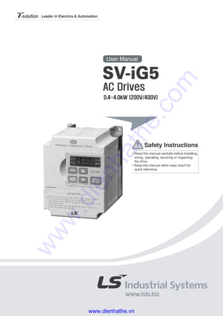
  • 2. Thank you for purchasing LS Variable Frequency Drives! SAFETY INSTRUCTIONS Always follow safety instructions to prevent accidents and potential hazards from occurring. In this manual, safety messages are classified as follows: WARNING CAUTION Throughout this manual we use the following two illustrations to make you aware of safety considerations: Identifies potential hazards under certain conditions. Read the message and follow the instructions carefully. Identifies shock hazards under certain conditions. Particular attention should be directed because dangerous voltage may be present. Keep operating instructions handy for quick reference. Read this manual carefully to maximize the performance of SV-iG5 series inverter and ensure its safe use. WARNING Do not remove the cover while power is applied or the unit is in operation. Otherwise, electric shock could occur. Do not run the inverter with the front cover removed. Otherwise, you may get an electric shock due to high voltage terminals or charged capacitor exposure. Do not remove the cover except for periodic inspections or wiring, even if the input power is not applied. Otherwise, you may access the charged circuits and get an electric shock. Wiring and periodic inspections should be performed at least 10 minutes after disconnecting the input power and after checking the DC link voltage Improper operation may result in slight to medium personal injury or property damage. Improper operation may result in serious personal injury or death. www.dienhathe.vn www.dienhathe.com
  • 3. is discharged with a meter (below DC 30V). Otherwise, you may get an electric shock. Operate the switches with dry hands. Otherwise, you may get an electric shock. Do not use the cable when its insulating tube is damaged. Otherwise, you may get an electric shock. Do not subject the cables to scratches, excessive stress, heavy loads or pinching. Otherwise, you may get an electric shock. CAUTION Install the inverter on a non-flammable surface. Do not place flammable material nearby. Otherwise, fire could occur. Disconnect the input power if the inverter gets damaged. Otherwise, it could result in a secondary accident and fire. After the input power is applied or removed, the inverter will remain hot for a couple of minutes. Otherwise, you may get bodily injuries such as skin-burn or damage. Do not apply power to a damaged inverter or to an inverter with parts missing even if the installation is complete. Otherwise, electric shock could occur. Do not allow lint, paper, wood chips, dust, metallic chips or other foreign matter into the drive. Otherwise, fire or accident could occur. OPERATING PRECAUTIONS (1) Handling and installation Handle according to the weight of the product. Do not stack the inverter boxes higher than the number recommended. Install according to instructions specified in this manual. Do not open the cover during delivery. www.dienhathe.vn www.dienhathe.com
  • 4. Do not place heavy items on the inverter. Check the inverter mounting orientation is correct. Do not drop the inverter, or subject it to impact. Follow your national electrical code for grounding. Recommended Ground impedance for 200 V Class is below 100 ohm and for 400V class is below 10 ohm. iG5 series contains ESD (Electrostatic Discharge) sensitive parts. Take protective measures against ESD (Electrostatic Discharge) before touching the pcb for inspection or installation. Use the inverter under the following environmental conditions: Ambient temperature - 10 ~ 40 ℃ (non-freezing) Relative humidity 90% RH or less (non-condensing) Storage temperature - 20 ~ 65 ℃ Location Protected from corrosive gas, combustible gas, oil mist or dust Altitude, Vibration Max. 1,000m above sea level, Max. 5.9m/sec2 (0.6G) or less Environment Atmospheric pressure 70 ~ 106 kPa (2) Wiring Do not connect a power factor correction capacitor, surge suppressor, or RFI filter to the output of the inverter. The connection orientation of the output cables U, V, W to the motor will affect the direction of rotation of the motor. Incorrect terminal wiring could result in the equipment damage. Reversing the polarity (+/-) of the terminals could damage the inverter. Only authorized personnel familiar with LG inverter should perform wiring and inspections. Always install the inverter before wiring. Otherwise, you may get an electric shock or have bodily injury. (3) Trial run Check all parameters during operation. Changing parameter values might be required depending on the load. Always apply permissible range of voltage to the each terminal as indicated in this manual. Otherwise, it could lead to inverter damage. (4) Operation precautions When the Auto restart function is selected, stay away from the equipment as a motor will restart suddenly after an alarm stop. www.dienhathe.vn www.dienhathe.com
  • 5. The Stop key on the keypad is valid only when the appropriate function setting has been made. Prepare an emergency stop switch separately. If an alarm reset is made with the reference signal present, a sudden start will occur. Check that the reference signal is turned off in advance. Otherwise an accident could occur. Do not modify or alter anything inside the inverter. Motor might not be protected by electronic thermal function of inverter. Do not use a magnetic contactor on the inverter input for frequent starting/stopping of the inverter. Use a noise filter to reduce the effect of electromagnetic interference. Otherwise nearby electronic equipment may be affected. In case of input voltage unbalance, install AC reactor. Power Factor capacitors and generators may become overheated and damaged due to potential high frequency noise transmitted from inverter. Use an insulation-rectified motor or take measures to suppress the micro surge voltage when driving 400V class motor with inverter. A micro surge voltage attributable to wiring constant is generated at motor terminals, and may deteriorate insulation and damage motor. Before operating unit and prior to user programming, reset user parameters to default settings. Inverter can easily be set to high-speed operations, Verify capability of motor or machinery prior to operating unit. Stopping torque is not produced when using the DC-Break function. Install separate equipment when stopping torque is needed. (5) Fault prevention precautions Provide a safety backup such as an emergency brake which will prevent the machine and equipment from hazardous conditions if the inverter fails. (6) Maintenance, inspection and parts replacement Do not conduct a megger (insulation resistance) test on the control circuit of the inverter. Refer to Chapter 6 for periodic inspection (parts replacement). (7) Disposal Handle the inverter as an industrial waste when disposing of it. (8) General instructions Many of the diagrams and drawings in this instruction manual show the inverter without a circuit breaker, a cover or partially open. Never run the inverter like this. Always place the cover with circuit breakers and follow this instruction manual when operating the inverter. www.dienhathe.vn www.dienhathe.com
  • 6. 1 CONTENTS USER SELECTION GUIDE (IG5 SPECIFICATIONS)..................................................................3 CHAPTER 1 - INSTALLATION .................................................................................................5 1.1 Inspection ............................................................................................................................................. 5 1.2 Environmental Conditions .................................................................................................................... 5 1.3 Mounting............................................................................................................................................... 5 1.4 Other Precautions................................................................................................................................ 6 1.5 Dimensions .......................................................................................................................................... 7 1.6 Basic Wiring ......................................................................................................................................... 8 1.7 Power Terminals .................................................................................................................................. 9 1.8 Control Terminals............................................................................................................................... 12 CHAPTER 2 - OPERATION ....................................................................................................15 2.1 Keypad and Parameter Group Setting .............................................................................................. 15 2.2 Parameter Setting and Change ......................................................................................................... 16 2.3 Parameter Group................................................................................................................................ 18 2.4 Operation............................................................................................................................................ 21 CHAPTER 3 - PARAMETER LIST ..........................................................................................23 3.1 Drive Group [DRV] ............................................................................................................................. 23 3.2 Function Group 1 [FU1]...................................................................................................................... 24 3.3 Function Group 2 [FU2]...................................................................................................................... 26 3.4 Input/Output Group [I/O] .................................................................................................................... 29 CHAPTER 4 - PARAMETER DESCRIPTION .........................................................................33 4.1 Drive Group [DRV] ............................................................................................................................. 33 4.2 Function 1 Group [FU1]...................................................................................................................... 38 4.3 Function 2 Group [FU2]...................................................................................................................... 49 4.4 Input/Output Group [I/O] .................................................................................................................... 61 CHAPTER 5 - MODBUS-RTU COMMUNICATION.................................................................73 5.1 Introduction......................................................................................................................................... 73 5.2 Specifications ..................................................................................................................................... 73 5.3 Installation .......................................................................................................................................... 74 5.4 Operating............................................................................................................................................ 75 5.5 Communication Protocol (Modbus-RTU)........................................................................................... 75 5.6 Communication Protocol (LS-BUS ASCII)......................................................................................... 76 5.7 Parameter Code List .......................................................................................................................... 80 5.8 Troubleshooting.................................................................................................................................. 86 5.9 ASCII Code List.................................................................................................................................. 88 www.dienhathe.vn www.dienhathe.com
  • 7. 2 CHAPTER 6 - TROUBLESHOOTING & MAINTENANCE ......................................................89 6.1 Fault Display ...................................................................................................................................... 89 6.2 Fault (Inverter Fault) Reset................................................................................................................ 91 6.3 Fault Remedy..................................................................................................................................... 92 6.4 Troubleshooting ................................................................................................................................. 93 6.5 How to Check Power Components.................................................................................................... 94 6.6 Maintenance....................................................................................................................................... 95 6.7 Daily and Periodic Inspection Items .................................................................................................. 96 CHAPTER 7 - OPTIONS..........................................................................................................99 7.1 Braking Resistor................................................................................................................................. 99 7.2 DIN Rail Base................................................................................................................................... 101 7.3 Remote Cable .................................................................................................................................. 102 7.4 NEMA option.................................................................................................................................... 102 APPENDIX A - FUNCTIONS BASED ON THE USE................................................................103 APPENDIX B- PERIPHERAL DEVICES ..................................................................................104 DECLARATION OF CONFORMITY.........................................................................................105 www.dienhathe.vn www.dienhathe.com
  • 8. 3 USER SELECTION GUIDE (IG5 SPECIFICATIONS) 230V Class (0.5~5.4HP) Inverter Type (SVxxxiG5-x) 004-1 008-1 015-1 004-2 008-2 015-2 022-2 037-2 040-2 HP 0.5 1 2 0.5 1 2 3 5 5.4Motor Rating1 kW 0.37 0.75 1.5 0.37 0.75 1.5 2.2 3.7 4.0 Capacity2 [kVA] 1.1 1.9 3.0 1.1 1.9 3.0 4.5 6.1 6.5 FLA [A] 3 5 8 3 5 8 12 16 17 Frequency 0.1 ~ 400 Hz Output Ratings Voltage 200 ~ 230 V 3 Voltage 1 Phase 200 ~ 230 V (± 10 %) 3 Phase 200 ~ 230 V (± 10 %) Input Ratings Frequency 50 ~ 60 Hz (±5 %) Braking Circuit On Board Average Braking Torque 20 % (Optional External DB Resistor: 100%, 150%) Max. Continuous Baking Time 15 seconds Dynamic Braking Duty 0 ~ 30 % ED Weight [lbs] 2.65 3.97 4.63 2.65 2.65 3.97 4.63 4.85 4.85 460V Class (0.5~ 5.4HP) Inverter Type (SVxxxiG5-x) 004-4 008-4 015-4 022-4 037-4 040-4 HP 0.5 1 2 3 5 5.4Motor Rating1 kW 0.37 0.75 1.5 2.2 3.7 4.0 Capacity2 [kVA] 1.1 1.9 3.0 4.5 6.1 6.5 FLA [A] 1.5 2.5 4 6 8 9 Frequency 0.1 ~ 400 Hz Output Ratings Voltage 380 ~ 460 V3 Voltage 3 Phase, 380 ~ 460 V (± 10 %)Input Ratings Frequency 50 ~ 60 Hz (±5 %) Braking Circuit On Board Average Braking Torque 20 % (Optional External DB Resistor: 100%, 150%) Max. Continuous Braking Time 15 seconds Dynamic Braking Duty 0 ~ 30 % ED Weight [lbs] 3.75 3.75 3.97 4.63 4.85 4.85 1 Indicates the maximum applicable capacity when using a 4 pole motor. 2 Rated capacity (√3*V*I) is based on 220V for 200V class and 440V for 400V class. 3 Maximum output voltage will not be greater than input voltage. Output voltage less than input voltage may be programmed. www.dienhathe.vn www.dienhathe.com
  • 9. 4 Control Method V/F Control Frequency Setting Resolution Digital Reference: 0.01 Hz (Below 100 Hz), 0.1 Hz (Over 100 Hz) Analog Reference: 0.03 Hz / 50 Hz Frequency Accuracy Digital: 0.01 % of Max. Output Frequency, Analog: 0.1 % of Max. Output Frequency V/F Ratio Linear, Square Patter, User V/F Overload Capacity 150 % of Rated Current for 1 Min. (Characteristic is inversely Proportional to Time) CONTROL Torque Boost Manual Torque Boost (0 ~ 15 %), Auto Torque Boost Operation Method Key / Terminal / Communication Operation Frequency Setting Analog: 0 ~ 10V / 4 ~ 20 mA Digital: Keypad Start Signal Forward, Reverse Multi-Step Speed Up to 8 Speeds Can Be Set (Use Multi-Function Terminal) Multi Step Accel/Decel Time 0 ~ 9,999 sec, Up to 4 Types Can Be Set and Selected for Each Setting (Use Multi- Function Terminal), Accel/Decel Pattern: Linear Pattern, U Pattern, S Pattern Emergency Stop Interrupts the Output of Inverter Jog Jog Operation InputSignal Fault Reset Reset Faults When Protective Function is Active Operating Status Frequency Level Detection, Overload Alarm, Stalling, Over Voltage, Under Voltage, Inverter Overheating, Running, Stop, Constant Speed, Speed Searching Fault Output Contact Output (A, C, B) – AC250V 1A, DC30V 1A OutputSignal Indicator Choose One From Output Frequency, Output Current, Output Voltage, DC Voltage (Output Voltage: 0 ~ 10V) OPERATION Operation Function DC Braking, Frequency Limit, Frequency Jump, Second Function, Slip Compensation, Reverse Rotation Prevention, Auto Restart, PID Control Inverter Trip Over Voltage, Under Voltage, Over Current, Inverter Overheating, Motor Over heating, Input/Output Phase Loss, Overload Protection, Communication Error, Loss of Speed Command, Hardware Fault Inverter Alarm Stall Prevention, Overload Alarm Protection Momentary Power Loss Less than 15 msec: Continuous Operation, More than 15 msec: Auto Restart (Programmable) Operation Information Output Frequency, Output Current, Output Voltage, Frequency Value Setting, Operating Speed, DC Voltage Display Keypad Trip Information Indicates Fault when Protection Function Activated, Memorizes Up to 5 Faults Ambient Temperature -10 °C ~ 40 °C (14 °F ~ 104 °F), CE Certification: 41 °F ~ 104 °F (5 °C ~ 40 °C) Storage Temperature -20 °C ~ 65 °C (-4 °F ~ 149 °F) Ambient Humidity Less Than 90 % RH Max. (Non-Condensing), CE Certification: 5 ~85% (Non-Condensing) Altitude / Vibration Below 1,000 m · Below 5.9m/sec² (=0.6g) Application Site No Corrosive Gas, Combustible Gas, Oil Mist, or Dust Environment Atmospheric Pressure 70 ~ 106kPa Cooling Method Forced Air Cooling4 4 ‘Self-cooling’ for model SV004iG5-4, SV008iG5-4. www.dienhathe.vn www.dienhathe.com
  • 10. 5 CHAPTER 1 - INSTALLATION 1.1 Inspection Inspect the inverter for any damage that may have occurred during shipping. Check the nameplate on the iG5 inverter. Verify the inverter unit is the correct one for the application. The numbering system of the inverter is as shown below. LS Inverter Applicable motor capacity Series name of inverter Input voltage 004: 0.5 HP iG5: 0.5 ~ 5.4 HP 1: 200 ~ 230V (1 Phase) 008: 1 HP iG: 1 ~ 5 HP 2: 200 ~ 230V (3 Phase) 015: 2 HP iS5: 1 ~ 100 HP 4: 380 ~ 460V (3 Phase) 022: 3 HP iS3: 1 ~ 30 HP 037: 5.0 HP iH: 40 ~ 300 HP 040: 5.4 Hp 1.2 Environmental Conditions Verify the ambient condition for the mounting location. - Ambient temperature should not be below 14ºF (-10ºC) or exceed 104ºF (40ºC). - Relative humidity should be less than 90% (non-condensing). - Altitude should be below 3,300ft (1,000m). Do not mount the inverter in direct sunlight and isolate it from excessive vibration. If the inverter is going to be installed in an environment with high probability of penetration of dust, it must be located inside watertight electrical boxes, in order to get the suitable IP degree. 1.3 Mounting The inverter must be mounted vertically with sufficient horizontal and vertical space between adjacent equipment (A= Over 6" (150mm), B= Over 2"(50mm)). A A BB 008SV iG5 2 www.dienhathe.vn www.dienhathe.com
  • 11. Chapter 1 - Installation 6 1.4 Other Precautions Do not carry the inverter by the front cover. Do not install the inverter in a location where excessive vibration is present. Be cautious when installing on presses or moving equipment. The life span of the inverter is greatly affected by the ambient temperature. Install in a location where temperature are within permissible limits (-10 ~ 40°C) (14~104°F). The inverter operates at high-temperatures - install on a non-combustible surface. Do not install the inverter in high-temperature or high-humidity locations. Do not install the inverter in a location where oil mist, combustible gas, or dust is present. Install the inverter in a clean location or in an enclosed panel, free of foreign substance. When installing the inverter inside a panel with multiple inverters or a ventilation fan, use caution. If installed incorrectly, the ambient temperature may exceed specified limits. Install the inverter using screws or bolts to insure the inverter is firmly fastened. If Carrier Frequency (FU2-39) must be set higher than 3 kHz, derate the load current by 5% per 1 kHz. Inverter GOOD (O) BAD (X) Inverter Cooling fan Panel Panel Inverter Inverter [When installing several inverters in a panel] GOOD (O) BAD (X) [When installing a ventilating fan in a panel] Ventilating fan www.dienhathe.vn www.dienhathe.com
  • 12. Chapter 1 - Installation 7 1.5 Dimensions Unit: mm (inch) Inverter HP W1 W2 H1 H2 D1 SV004iG5-1 0.5 100 (3.94) 88 (3.46) 128 (5.04) 117.5 (4.63) 130.9 (5.15) SV008iG5-1 1 130 (5.12) 118 (4.65) 128 (5.04) 117.5 (4.63) 152.9 (6.02) SV015iG5-1 2 150 (5.90) 138 (5.43) 128 (5.04) 117.5 (4.63) 155.0 (6.10) SV004iG5-2 0.5 100 (3.94) 88 (3.46) 128 (5.04) 117.5 (4.63) 130.9 (5.15) SV008iG5-2 1 100 (3.94) 88 (3.46) 128 (5.04) 117.5 (4.63) 130.9 (5.15) SV015iG5-2 2 130 (5.12) 118 (4.65) 128 (5.04) 117.5 (4.63) 152.9 (6.02) SV022iG5-2 3 150 (5.90) 138 (5.43) 128 (5.04) 117.5 (4.63) 155.0 (6.10) SV037iG5-2 5.0 150 (5.90) 138 (5.43) 128 (5.04) 117.5 (4.63) 155.0 (6.10) SV040iG5-2 5.4 150 (5.90) 138 (5.43) 128 (5.04) 117.5 (4.63) 155.0 (6.10) SV004iG5-4 0.5 130 (5.12) 118 (4.65) 128 (5.04) 117.5 (4.63) 152.9 (6.02) SV008iG5-4 1 130 (5.12) 118 (4.65) 128 (5.04) 117.5 (4.63) 152.9 (6.02) SV015iG5-4 2 130 (5.12) 118 (4.65) 128 (5.04) 117.5 (4.63) 152.9 (6.02) SV022iG5-4 3 150 (5.90) 138 (5.43) 128 (5.04) 117.5 (4.63) 155.0 (6.10) SV037iG5-4 5.0 150 (5.90) 138 (5.43) 128 (5.04) 117.5 (4.63) 155.0 (6.10) SV040iG5-4 5.4 150 (5.90) 138 (5.43) 128 (5.04) 117.5 (4.63) 155.0 (6.10) www.dienhathe.vn www.dienhathe.com
  • 13. Chapter 1 - Installation 8 1.6 Basic Wiring 230/460V 50/60Hz U V W G R S T or 3 Φ, MCCB FX RX BX RST P1 P3 CM VR V1 I CM + FM CM 30A 30B 30C MO MG Output Frequency Meter (0~10V Analog) P2 MOTOR Potentiometer (1 kohm, 1/2W) Speed signal Input1 Forward Run/Stop Reverse Run/Stop Inverter Disable Fault Reset Multi-function Input 1 Multi-function Input 2 Multi-function Input 3 Common Terminal Factory Setting: ‘Speed-L’ ‘Speed-M’ ‘Speed-H’ Power supply for speed signal: + 12V, 10mA Speed signal input: 0 ~ 10V Speed signal input: 4 ~20mA (250ohm) Common for VR, V1, I Fault output relay Less than AC250V, 1A Less than DC30V, 1A Less than DC24V, 50mA Factory setting: ‘Run’ Note) display main circuit terminals, display control circuit terminals. 1. Analog speed command can be set by Voltage, Current and both of them. 2. DB resistor is optional. B2B1 FM JOG Jog Shield DB Resistor2 RS485 & MODBUS-RTU Communication port S+ S- 1Φ, 230V www.dienhathe.vn www.dienhathe.com
  • 14. Chapter 1 - Installation 9 1.7 Power Terminals R S T B1 B2 U V W Symbols Functions R S T AC Line Input Terminals 3(1) phase, 200 ~ 230V AC for 200V Class Units and 380 ~ 460V AC for 400V Class Units. 1 Phase Input Terminals: R and T U V W 3 Phase Output Terminals to Motor (3 Phase, 200 ~ 230VAC or 380 ~ 460VAC) B1 B2 Dynamic Braking Resistor Connection Terminals “Suitable for use on a circuit capable of delivering not more than 10,000 rms symmetrical amperes, 240 volts maximum for 230V class models and 480 volts maximum for 460V class models.” 1.7.1 Wiring Power Terminals Precautions on Wiring The internal circuits of the inverter will be damaged if the incoming power is connected and applied to output terminals (U, V, W). Use ring terminals with insulated caps when wiring the input power and motor wiring. Do not leave wire fragments inside the inverter. Wire fragments can cause faults, breakdowns, and malfunctions. Normal stray capacitance between the inverter chassis and the power devices inside the inverter and AC line can provide a high impedance shock hazard. Do not apply power to the inverter if the inverter frame (Power terminal G) is not grounded. Motor DB Resistor 3 Phase Power Input: R, S, T 1 Phase Power Input: R, T WARNING WARNING www.dienhathe.vn www.dienhathe.com
  • 15. Chapter 1 - Installation 10 For input and output, use wires with sufficient size to ensure voltage drop of less than 2%. Motor torque may drop if operating at low frequencies and a long wire run between inverter and motor. When more than one motor is connected to one inverter, total wiring length should be less than 500m (1,640ft). Do not use a 3-wire cable for long distances. Due to increased leakage capacitance between wires, over-current protective feature may operate or equipment connected to the output side may malfunction. Connect only recommended braking resistor between the B1 and B2 terminals. Never short B1 and B2 terminals. Shorting terminals may cause internal damage to inverter. The main circuit of the inverter contains high frequency noise, and can hinder communication equipment near the inverter. To reduce noise, install RFI filters or line noise filters on the input side of the inverter. Do not use power factor capacitor, surge suppressors, or RFI filters on the output side of the inverter. Doing so may damage these components. Always insure the LED and charge lamp for the power terminal are OFF before wiring terminals. The charge capacitor may hold high-voltage even after the power is disconnected. Use caution to prevent the possibility of personal injury. Grounding The inverter is a high switching device, and leakage current may flow. Ground the inverter to avoid electrical shock. Use caution to prevent the possibility of personal injury. Connect only to the dedicated ground terminal on the inverter. Do not use the enclosure or a chassis screw for grounding. The protective earth conductor must be the first one in being connected and the last one in being disconnected. As a minimum, grounding wire should meet the specifications listed below. Grounding wire should be as short as possible and should be connected to the ground point as near as possible to the inverter. Grounding Wire Sizes, AWG (mm²) Motor Capacity 200V class 400V class 0.5 ~ 5.4 HP 12 (3.5) 14 (2) Ground Screw WARNING www.dienhathe.vn www.dienhathe.com
  • 16. Chapter 1 - Installation 11 Wires and Terminal Lugs Refer to the following table for wires, terminal lugs and screws used to connect the inverter power input (R, S, T) and output (U, V, W). Wire6 Ring Terminals mm2 AWGInverter Terminal Screw Size Screw Torque5 (Kgf·cm)/lb-in R,S,T U,V,W R,S,T U,V,W R,S,T U,V,W 0.5 HP M 3.5 10 / 7 2-3.5 2-3.5 2 2 14 14200V Class (1 Phase) 1 ~ 2 HP M 4.0 15 / 10 2-4 2-4 2 2 14 14 0.5 ~ 1 HP M 3.5 10 / 7 2-3.5 2-3.5 2 2 14 14 2 ~ 3 HP M 4.0 15 / 10 2-4 2-4 2 2 14 14 200V Class (3 Phase) 5 ~ 5.4 HP M 4.0 15 / 10 5.5-4 5.5-4 3.5 3.5 12 12 400V Class (3 Phase) 0.5 ~ 5.4 HP M 4.0 15 / 10 2-4 2-4 2 2 14 14 Power and Motor Connection R S T B1 B2 U V W 5 Apply the rated torque to terminal screws. Loosen screws can cause of short circuit and malfunction. Tightening the screws too much can damage the terminals and cause short circuit and malfunction. 6 Use copper wires with 600V, 75℃ratings for wiring only. Power supply must be connected to the R, S, and T Terminals. Connecting it to the U, V, W terminals causes internal damages to the inverter. Arranging the phase sequence is not necessary. Motor should be connected to the U, V, and W Terminals. If the forward command (FX) is on, the motor should rotate counter clockwise when viewed from the load side of the motor. If the motor rotates in the reverse, switch the U and V terminals. Motor3 Phase Power Input: R, S, T 1 Phase Power Input: R, T WARNING WARNING www.dienhathe.vn www.dienhathe.com
  • 17. Chapter 1 - Installation 12 1.8 Control Terminals 30A 30C 30B 1 MO 2 MG 3 CM 4 FX 5 RX 6 CM 7 BX 8 JOG 9 RST 10 CM 1 P1 2 P2 3 P3 4 VR 5 V1 6 CM 7 I 8 FM 9 S+ 10 S- Wire Size Terminal Name Terminal Screw Size Screw Torque (Kgf·cm/lb-in) Solid Wire (mm2) Stranded Wire (mm2) Stripped Length (mm) 30A, 30C, 30B M3 5 / 3.6 2.5 1.5 7 MO, MG, CM, FX, RX ~ S- M2 4 / 2.9 1.5 1.0 5.5 Type Symbol Name Description P1, P2, P3 Multi-Function Input 1, 2, 3 Used for Multi-Function Input. Default is set to “Step Frequency 1, 2, 3”. FX Forward Run Command Forward Run When Closed and Stop When Open. RX Reverse Run Command Reverse Run When Closed and Stop When Open. JOG Jog Frequency Reference Runs at Jog Frequency. The Direction is set by the FX (or RX) Signal. BX Emergency Stop When the BX Signal is ON Output of Inverter is Turned Off. When Motor uses an Electrical Brake to Stop, BX is used to Turn Off the Output Signal. When BX Signal is OFF (Not Turned Off by Latching) and FX Signal (or RX Signal) is ON, Motor continues to Run. RST Fault Reset Used for Fault Reset. StartingContactFunctionSelect CM Sequence Common Common Terminal for Contact Inputs. VR Frequency Setting Power (+10V) Used as Power for Analog Frequency Setting. Maximum Output is +12V, 10mA. V1 Frequency Reference (Voltage) Used for 0-10V Input Frequency Reference. Input Resistance is 20 KΩ I Frequency Reference (Current) Used for 4-20mA Input Frequency Reference. Input Resistance is 250 Ω Inputsignal Analogfrequencysetting CM Frequency Setting Common Terminal Common Terminal for Analog Frequency Reference Signal and FM (For Monitoring). Analog FM-CM Analog Output (For External Monitoring) Outputs One of the Following: Output Frequency, Output Current, Output Voltage, DC Link Voltage. Default is set to Output Frequency. Maximum Output Voltage and Output Current are 0-12V and 1mA. 30A 30C 30B Fault Contact Output Activates when Protective Function is Operating. AC250V, 1A or less; DC30V, 1A or less. Fault: 30A-30C Short (30B-30C Open), Normal: 30B-30C Short (30A-30C Open) Outputsignal Contact MO - MG Multi-Function Output (Open Collector Output) Use After Defining Multi-Function Output Terminal. DC24V, 50mA or less. RS-485 S+, S- Communication Port Communication Port for MODBUS-RTU Communication ! www.dienhathe.vn www.dienhathe.com
  • 18. Chapter 1 - Installation 13 1.8.1 Wiring Control Terminals Precautions on Wiring Use shielded wires or twisted wires for control circuit wiring, and separate these wires from the main power circuits and other high voltage circuits. Control Circuit Terminal The input terminals can be selected for either NPN or PNP type logic by changing switch J1. CM terminal is the common terminal for the input signals. 24 V FX CM Resistor CM J1 NPN SW J1 Inside Inverter 24 V FX CM Resistor CM J1 DC24V PNP SW J1 Inside Inverter www.dienhathe.vn www.dienhathe.com
  • 19. Chapter 1 - Installation 14 1.8.2 Keypad Wiring the Keypad Keypad is installed before shipping for standard type models as shown below. When using an optional remote cable, install the buffer cover and connect the remote cable. If the keypad is not connected properly, the letters will not be displayed. ☞ Note: Do not connect the keypad and remote cable while the inverter is under power. ☞ Note: Do not touch the live part of the keypad connector. Doing this may cause an electric shock or personal injury. Keypad Connector Pin Configuration (Inverter Side) Pin No. Pin Name Keypad Description 1 5V Used 5V DC Power Supply (Isolated from VR, V1, I of Control Terminal) 2 GND Used 5V DC Power Ground (Isolated from CM of Control Terminal) 3 RES Used 4 VPP Used Used for Writing Flash ROM Inside Inverter. 5 LAT Used Latch Signal for Transmitting/Receiving 6 TXD Used Transmitting Signal Pin 7 CLK Used Clock Signal Pin 8 RXD Used Receiving Signal Pin 9 Not Used 10 Not Used 2 4 6 8 10 1 3 5 7 9 (Top View) Keypad (Detachable) www.dienhathe.vn www.dienhathe.com
  • 20. 15 CHAPTER 2 - OPERATION 2.1 Keypad and Parameter Group Setting 2.1.1 Keypad Description 7-Segment keypad displays up to 4 letters and numbers, and the user can directly check various settings of the inverter. The following is an illustration of the keypad and the functions of each part. Class Display Name Description FUNC Program Key Press to Change Parameter Setting. ▲ (Up) Up Key Press to Move Through Codes or To Increase Parameter Values. ▼ (Down) Down Key Press to Move Through Codes or To Decrease Parameter Values. RUN Run Key Use to Operate Inverter. Key STOP/RESET STOP/RESET Key Press to Stop Inverter During Operation. Press to Reset When a Fault Has Occurred. REV Reverse Run Display Lit During Reverse Run. FWD Forward Run Display Lit During Forward Run. SET Setting Lit When User is Setting Parameters Using FUNC Key LED RUN Operating Lit When at Constant Speed and Blinks When Accelerating or Decelerating. SET LED RUN LED UP/DOWN Key STOP/RESET Key FUNC Key RUN Key FWD LED REV LED SET RUN FWD REV FUNC RUN STOP RESET LE-100 DISPLAY (7-Segment) www.dienhathe.vn www.dienhathe.com
  • 21. Chapter 2 - Operation 16 2.2 Parameter Setting and Change Numerous parameters are built into the inverter. The keypad allows the operator to operate the inverter by setting the required parameters, and enter the proper value according to the load and operating conditions. Refer to Chapter 4 ‘PARAMETER DESCRIPTION’ for detailed description of the functions. Procedures First move to the group code that needs changing. Press [FUNC] key. The keypad LED (SET) will turn ON. Use the [▲ (Up)], [▼ (Down)] keys to set the data to the desired value. Press [FUNC] key again. The data display will blink and the data will be stored in the inverter. ☞ Note: If the data does not changed, determine if: - Inverter is running (Refer to the function table in Chapter 3) - Function is locked in H 94 [Parameter Lock] Setting the DRV Group Data Example) Change the acceleration time from 60 sec to 40 sec: Data will blink when the data setting is finished. Indicates data programming is complete. To Monitor Current Output from the DRV Group Example) Monitor current output from inverter (Data cannot be set): RUN SET FWD REV RUN SET FWD REV FUNC RUN SET FWD REV FUNC RUN SET FWD REV RUN SET FWD REV RUN SET FWD REV FUNC RUN SET FWD REV FUNC www.dienhathe.vn www.dienhathe.com
  • 22. Chapter 2 - Operation 17 To Monitor Fault Type when a Fault Occurs (Data cannot be set) The fault type is displayed on the DRV group when a fault occurs. Frequency, current and operating status (accelerating, decelerating, in constant speeds) may be monitored by using the UP, DOWN arrow keys. (Ex: Fault occurred when the inverter was accelerating at 40.28 Hz, 20.5A) 4 LED is blinking in this situation. Fault status can be removed by using the STOP/RESET Key, and the LED turns OFF. (The inverter must be turned OFF and turned ON again to remove HW fault status.) Adjusting Function and I/O Group Data Example) Changing the F5 data to 1: Frequency Trip Current During Accel RUN SET FWD REV RUN SET FWD REV FUNC FUNC RUN SET FWD REV RUN FWDSET REV RUN SET FWD REV RUN SET FWD REV RUN SET FWD REVRUN SET FWD REV RUN SET FWD REV FUNC FUNC FUNC FUNC RUN SET FWD REV RUN SET FWD REV RUN SET FWD REV www.dienhathe.vn www.dienhathe.com
  • 23. Chapter 2 - Operation 18 Setting Jump Code in Function Group Example) Jump to code FU1-12 from FU1-0 (F 0): 2.3 Parameter Group The iG5 series offers a 7-segment (LED) keypad for the user. Parameters are separated into 4 function groups according to their application fields. The groups’ names and the descriptions are as follows. Group Name Description Drive group Basic Parameters: Command Frequency, Accel/Decel Time, etc. Function 1 group Basic Parameters: Max. Frequency, Torque Boost, etc. Function 2 Group Application Parameters: Frequency Jump, Frequency Limit, etc. Input/Output group Multi-Function Terminal Setting and Sequence Operation Parameters Refer to the parameter description in Chapter 4 for detailed description of each group. RUN SET FWD REV FUNC RUN SET FWD REV FUNC RUN SET FWD REV RUN SET FWD REV FUNC RUN SET FWD REV www.dienhathe.vn www.dienhathe.com
  • 24. Chapter 2 - Operation 19 Moving Through DRV Group Codes RUN SET FWD REV RUN SET FWD REV RUN SET FWD REV REVRUN SET FWD REVRUN SET FWD RUN SET FWD REV RUN SET FWD REV REVRUN SET FWD REVRUN SET FWD REVRUN SET FWD REVRUN SET FWD RUN SET FWD REV RUN SET FWD REV RUN SET FWD REV RUN SET FWD REV RUN SET FWD REV RUN SET FWD REV www.dienhathe.vn www.dienhathe.com
  • 25. Chapter 2 - Operation 20 Moving Through Function Group Codes Moving Through I/O Group Codes RUN SET FWD REV RUN SET FWD REV RUN SET FWD REV RUN SET FWD REV FUNC FUNC RUN SET FWD REV RUN SET FWD REV FUNC RUN SET FWD REV RUN SET FWD REV FUNC www.dienhathe.vn www.dienhathe.com
  • 26. Chapter 2 - Operation 21 Note: The user may also operate the inverter by setting the operation reference signal from the Keypad, and setting the frequency reference signal to the control terminal. (Set DRV-03 (drv) to 0 (Keypad), and the DRV-04 (Frq) to 2 (V1), 3(I), 4(V1+I)). Note: FU1-20, FU1-21, FU1-25, FU1-36, FU2-54, FU2-83, I/O-05, I/O-10 are set at 50Hz for Standard (EU) types and 60Hz for US types. 2.4 Operation 2.4.1 Operation From Keypad and Control Terminal When the operation reference signal is given to the control terminal and the frequency setpoint is given by the keypad, set the DRV-03 (drv) to 1 (Fx/Rx-1), and set the DRV-04 (Frq) to 0 (Keypad-1). The frequency reference signal is set from the control terminal, and the forward, reverse, stop key of the keypad is invalid. 1. Turn the power ON and set the operation and the frequency parameters. 2. Set the DRV-03 (drv) to 1 (Fx/Rx-1), and the DRV-04 (Frq) to 0 (Keypad-1). 3. Turn ON the operation reference signal FX (or RX). Keypad LED (FWD key or REV key) will turn ON. 4. Set the operating frequency with the keypad. Use the FUNC, ▲ (Up), FUNC keys and set the frequency to 50.00Hz. The motor will rotate at 50Hz. The LED (RUN) of the keypad will blink when the inverter is accelerating or decelerating. 5. Turn the operation reference signal FX (or RX) OFF. The LED (FWD of REV) of the keypad will turn OFF. 2.4.2 Operation From Control Terminal 1. Turn the power ON and set the operation and the frequency reference to the control terminal mode. 2. Set the DRV-03 (drv) to 1 (Fx/Rx-1), and the DRV-04 (Frq) to 2 (V1), 3(I), 4 (V1+I). 3. Set the analog frequency reference by turning the potentiometer (frequency reference) slowly to the right or increasing current ranging from 4 to20mA.. The keypad will display the output frequency (50.00 Hz). 4. Slowly turning the potentiometer (frequency reference) to the left will decreasing current ranging from 20 to 4 mA will reduce the output frequency. The inverter will stop operating and the motor will come to a halt when the frequency reaches 0.00Hz. 5. Turn OFF the operation reference signal FX (or RX). www.dienhathe.vn www.dienhathe.com
  • 27. Chapter 2 - Operation 22 2.4.3 Operation From Keypad 1. Turn the power ON and set the operation and frequency reference to ‘keypad operating mode’. 2. Set the DRV-03 (drv) to 0 (Keypad), and the Frq [Frequency Reference Source Selection] to Keypad-1. 3. Use FUNC, ▲ (Up) key to set the operating frequency to 50.00Hz. When the inverter is not running the command frequency is displayed. 4. Press the RUN key. The motor will rotate and the keypad will display the output frequency. 5. Press the STOP/RESET key. The motor will decelerate and come to a halt, and the keypad will display the command frequency. www.dienhathe.vn www.dienhathe.com
  • 28. 23 CHAPTER 3 - PARAMETER LIST 3.1 Drive Group [DRV] Code Description Keypad Display Setting Range Units Factory Default Adj. During Run Page DRV-00 Output Frequency during running, Reference Frequency during stop 0.00 0.00 to (FU1-20) 0.01 00.00 [Hz] Yes 33 DRV-01 Acceleration Time ACC 0.0 to 999.9 [sec] 0.1 10.0 [sec] Yes 33 DRV-02 Deceleration Time DEC 0.0 to 999.9 [sec] 0.1 20.0 [sec] Yes 33 0 (keypad) 1 (Fx/Rx-1) 2 (Fx/Rx-2) DRV-03 Drive Mode (Run/Stop Method) Drv 3 (RS485) - 1 (Fx/Rx-1) No 34 0 [Keypad-1] 1 (Keypad-2) 2 (V1) 3 (I) 4 (V1+I) DRV-04 Frequency Mode (Freq. Setting Method) Frq 5 (RS485) - 0 [Keypad-1] No 34 DRV-05 Step Frequency 1 St1 10.00 [Hz] DRV-06 Step Frequency 2 St2 20.00 [Hz] DRV-07 Step Frequency 3 St3 0.00 to (FU1-20) 0.01 30.00 [Hz] Yes 35 DRV-08 Output Current Cur * [A] - - [A] - 35 DRV-09 Motor Speed RPM * [rpm] - - [rpm] - 35 DRV-10 DC link Voltage DCL * [V] - - [V] - 36 DRV-11 User Display Selection vOL, Por, tOr Selected in FU2-73 (User disp) - - - 36 DRV-12 Fault Display nOn - - None nOn - 36 F (Forward) DRV-13 Motor Direction Set drc r (Reverse) - F (Forward) Yes 36 DRV-20 FU1 Group Selection FU1 37 DRV-21 FU2 Group Selection FU2 37 DRV-22 I/O Group Selection I O 37 www.dienhathe.vn www.dienhathe.com
  • 29. Chapter 3 - Parameter List 24 3.2 Function Group 1 [FU1] Code Description Keypad Display Setting Range Units Factory Default Adj. During Run Page FU1-00 Jump to Desired Code # F 0 1 to 99 1 3 Yes 38 0 (None) 1 (Forward Prev)FU1-03 Run Prevention F 3 2 (Reverse Prev) - 0 (None) No 38 0 (Linear) 1 (S-Curve) 2 (U-Curve) 3 (Minimum) FU1-05 Acceleration Pattern F 5 4 (Optimum) - 0 (Linear) No 38 0 (Linear) 1 (S-Curve) 2 (U-Curve) 3 (Minimum) FU1-06 Deceleration Pattern F 6 4 (Optimum) - 0 (Linear) No 38 0 (Decel) 1 (DC-Brake)FU1-07 Stop Mode F 7 2 (Free-Run) - 0 (Decel) No 39 FU1-087 DC Injection Braking Frequency F 8 (FU1-22) to 50/60 [Hz] 0.01 5.00 [Hz] No FU1-09 DC Injection Braking On-delay Time F 9 0 to 60 [sec] 0.01 0.10 [sec] No FU1-10 DC Injection Braking Voltage F 10 0 to 200 [%] 1 50 [%] No FU1-11 DC Injection Braking Time F 11 0 to 60 [sec] 0.1 1.0 [sec] No 40 FU1-12 Starting DC Injection Braking Voltage F 12 0 to 200 [%] 1 50 [%] No FU1-13 Starting DC Injection Braking Time F 13 0.0 to 60.0 [sec] 0.1 0.0 [sec] No 40 FU1-20 Maximum Frequency F 20 40.00 to 400.00 [Hz] 0.01 50 / 60 [Hz] No FU1-21 Base Frequency F 21 30.00 to (FU1-20) 0.01 50 / 60 [Hz] No FU1-22 Starting Frequency F 22 0.10 to 10.00 [Hz] 0.01 0.10 [Hz] No 41 0 (No) FU1-23 Frequency Limit Selection F 23 1 (Yes) - 0 (No) No FU1-248 Low Limit Frequency F 24 0.00 to (FU1-25) 0.01 0.00 [Hz] No FU1-25 High Limit Frequency F 25 (FU1-24) to (FU1-20) 0.01 50 / 60 [Hz] No 41 0 (Manual) FU1-26 Manual/Auto Torque Boost Selection F 26 1 (Auto) - 0 (Manual) No FU1-27 Torque Boost in Forward Direction F 27 0.1 2.0 [%] No FU1-28 Torque Boost in Reverse Direction F 28 0.0 to 15.0 [%] 0.1 2.0 [%] No 42 7 Code FU1-08 through FU1-11 appears only when FU1-07 is set to ‘DC-brake’. 8 Code FU1-24 through FU1-25 appears only when FU1-23 is set to ‘Yes’. www.dienhathe.vn www.dienhathe.com
  • 30. Chapter 3 - Parameter List 25 Code Description Keypad Display Setting Range Units Factory Default Adj. During Run Page 0 (Linear) 1 (Square)FU1-29 Volts/Hz Pattern F 29 2 (User V/F) - 0 (Linear) No 43 FU1-309 User V/F – Frequency 1 F 30 0.00 to (FU1-32) 0.01 15.00 [Hz] No FU1-31 User V/F – Voltage 1 F 31 0 to 100 [%] 1 25 [%] No FU1-32 User V/F – Frequency 2 F 32 (FU1-30) to (FU1-34) 0.01 30.00 [Hz] No FU1-33 User V/F – Voltage 2 F 33 0 to 100 [%] 1 50 [%] No FU1-34 User V/F – Frequency 3 F 34 (FU1-32) to (FU1-36) 0.01 45.00 [Hz] No FU1-35 User V/F – Voltage 3 F 35 0 to 100 [%] 1 75 [%] No FU1-36 User V/F – Frequency 4 F 36 (FU1-34) to (FU1-20) 0.01 50 / 60 [Hz] No FU1-37 User V/F – Voltage 4 F 37 0 to 100 [%] 1 100 [%] No 43 FU1-38 Output Voltage Adjustment F 38 40 to 110 [%] 0.1 100.0 [%] No 44 FU1-39 Energy Save Level F 39 0 to 30 [%] 1 0 [%] Yes 44 0 (No) FU1-50 Electronic Thermal Selection F 50 1 (Yes) - 0 (No) Yes FU1-5110 Electronic Thermal Level for 1 Minute F 51 FU1-52 to 250 [%] 1 180 [%] Yes FU1-52 Electronic Thermal Level for Continuous F 52 50 to FU1-51 1 120 [%] Yes 0 (Self-cool) FU1-53 Electronic Thermal Characteristic Selection (Motor type) F 53 1 (Forced-cool) - 0 (Self-cool) Yes 45 FU1-54 Overload Warning Level F 54 30 to 250 [%] 1 150 [%] Yes FU1-55 Overload Warning Hold Time F 55 0 to 30 [sec] 0.1 10.0 [sec] Yes 46 0 (No) FU1-56 Overload Trip Selection F 56 1 (Yes) - 1 (Yes) Yes FU1-5711 Overload Trip Level F 57 30 to 250 [%] 1 200 [%] Yes FU1-58 Overload Trip Delay Time F 58 0 to 60 [sec] 1 60.0 [sec] Yes 46 FU1-59 Stall Prevention Mode Selection F 59 000 – 111 (bit set) Bit 0: during Accel. Bit 1: during Steady speed Bit 2: during Decel. bit 000 No FU1-60 Stall Prevention Level F 60 30 to 250 [%] 1 200 [%] No 47 FU1-99 Return Code rt - - - 48 9 Code FU1-30 through FU1-37 appears only when FU1-29 is set to ‘User V/F’. 10 Code FU1-51 through FU1-53 appears only when FU1-50 is set to ‘Yes’. 11 Code FU1-57 through FU1-58 appears only when FU1-56 is set to ‘Yes’. www.dienhathe.vn www.dienhathe.com
  • 31. Chapter 3 - Parameter List 26 3.3 Function Group 2 [FU2] Code Description Keypad Display Setting Range Units Factory Default Adj. During Run Page FU2-00 Jump to Desired Code # H 0 1 to 99 1 30 Yes 49 FU2-01 Previous Fault History 1 H 1 FU2-02 Previous Fault History 2 H 2 FU2-03 Previous Fault History 3 H 3 FU2-04 Previous Fault History 4 H 4 FU2-05 Previous Fault History 5 H 5 - None n0n - 0 (No) FU2-06 Erase Fault History H 6 1 (Yes) - 0 (No) Yes 49 FU2-07 Dwell Frequency H 7 0 to FU1-20 0.01 5.00 [Hz] No FU2-08 Dwell Time H 8 0 to 10 [sec] 0.1 0.0 [sec] No 49 0 (No) FU2-10 Frequency Jump Selection H 10 1 (Yes) - 0 (No) No FU2-1112 Jump Frequency 1 Low H 11 0.00 to (FU2-12) 0.01 0.00 [Hz] No FU2-12 Jump Frequency 1 High H 12 (FU2-11) to (FU1-20) 0.01 0.00 [Hz] No FU2-13 Jump Frequency 2 Low H 13 0.00 to (FU2-14) 0.01 0.00 [Hz] No FU2-14 Jump Frequency 2 High H 14 (FU2-13) to (FU1-20) 0.01 0.00 [Hz] No FU2-15 Jump Frequency 3 Low H 15 0.00 to (FU2-16) 0.01 0.00 [Hz] No FU2-16 Jump Frequency 3 High H 16 (FU2-15) to (FU1-20) 0.01 0.00 [Hz] No 50 FU2-19 Input/Output Phase Loss Protection H 19 00 – 11 (bit set) Bit 0: Output Phase Loss Protection Bit 1: Input Phase Loss Protection - 00 Yes 50 0 (No) FU2-20 Power ON Start Selection H 20 1 (Yes) - 0 (No) Yes 51 0 (No) FU2-21 Restart after Fault Reset H 21 1 (Yes) - 0 (No) Yes 51 FU2-22 Speed Search Selection H 22 0000 – 1111 (bit set) Bit 0: During Accel. Bit 1: After Fault reset Bit 2: After Instant Power Failure restart Bit 3: When FU2-20 is set to 1 (Yes). - 0000 No 52 FU2-23 Current Limit Level During Speed Search H 23 80 to 250 [%] 1 180 [%] Yes 52 12 Code FU2-11 through FU2-16 appears only when FU2-10 is set to ‘Yes’. www.dienhathe.vn www.dienhathe.com
  • 32. Chapter 3 - Parameter List 27 Code Description Keypad Display Setting Range Units Factory Default Adj. During Run Page FU2-24 P Gain During Speed Search H 24 0 to 9999 1 100 Yes 52 FU2-25 I Gain During speed search H 25 0 to 9999 1 5000 Yes 52 FU2-26 Number of Auto Restart Attempt H 26 0 to 10 1 0 Yes FU2-27 Delay Time before Auto Restart H 27 0 to 60 [sec] 0.1 1.0 [sec] Yes 53 FU2-30 Rated Motor Selection H 30 0.4 (0.37kW) 0.8 (0.75kW) 1.5 (1.5kW) 2.2 (2.2kW) 3.7 (3.7kW) 4.0 (4.0kW) - 13 No 53 FU2-31 Number of Motor Pole H 31 2 to 12 1 4 No FU2-3214 Rated Motor Slip H 32 0 to 10 [Hz] 0.01 No FU2-33 Rated Motor Current in RMS H 33 0.1 to 99.9 [A] 1 No FU2-3415 No Load Motor Current in RMS H 34 0.1 to 99.9 [A] 1 No FU2-36 Motor Efficiency H 36 50 to 100 [%] 1 14 No FU2-37 Load Inertia H 37 0 to 2 1 0 No 53 FU2-39 Carrier Frequency H 39 1 to 10 [kHz] 1 3 [kHz] Yes 54 0 (V/F) 1 (Slip Compen)FU2-40 Control Mode Selection H 40 2 (PID) - 0 (V/F) No 55 0 (I) FU2-5016 PID Feedback Signal Selection H 50 1 (V1) - I 0 No FU2-51 P Gain for PID Control H 51 0 to 9999 1 3000 Yes FU2-52 I Gain for PID Control H 52 0 to 9999 1 300 Yes FU2-53 D Gain for PID Control H 53 0 to 9999 1 0 Yes FU2-54 Limit Frequency for PID Control H 54 0 to FU1-20 0.01 50 / 60 [Hz] Yes 55 0 (Max Freq) FU2-70 Reference Frequency for Accel and Decel H 70 1 (Delta Freq) - Max frq 0 No 56 0 (0.01 sec) 1 (0.1 sec)FU2-71 Accel/Decel Time Scale H 71 2 (1 sec) - 1 (0.1 sec) Yes 57 0 (Cmd. Freq) 1 (Acc. Time) FU2-72 Power On Display H 72 2 (Dec. Time) 1 0 (Cmd. Freq) Yes 57 13 The rated motor is automatically set according to the inverter model number. If a different motor is used, set the correct motor parameters. 14 This value is automatically entered according to the rated motor set in FU2-30. If different, set the correct motor parameters. 15 Code FU2-32 and FU2-34 appear only when FU2-40 is set to ‘Slip comp’. 16 Code FU2-50 through FU2-54 appears only when FU2-40 is set to ‘PID’. www.dienhathe.vn www.dienhathe.com
  • 33. Chapter 3 - Parameter List 28 Code Description Keypad Display Setting Range Units Factory Default Adj. During Run Page 3 (Drv Mode) 4 (Freq Mode) 5 (Step Freq 1) 6 (Step Freq 2) 7 (Step Freq 3) 8 (Current) 9 (Speed) 10(DC Link Vtg) 11 (User Display) 12 (Fault Display) 13 (Motor Direction) 0 (Voltage) 1 (Watt)FU2-73 User Display Selection H 73 2 (Torque) - 0 (Voltage) Yes 57 FU2-74 Gain for Motor Speed Display H 74 1 to 1000 [%] 1 100 [%] Yes 57 0 (None) 1 (None)FU2-75 DB (Dynamic Braking) Resistor Mode Selection H 75 2 (Ext. DB-R) - 2 (Ext. DB-R) Yes 58 FU2-76 Duty of Dynamic Braking Resistor H 76 0 to 30 [%] 1 10 [%] Yes 58 FU2-79 Software Version H 79 . - . - 58 FU2-8117 2nd Acceleration Time H 81 0.0 to 999.9 [sec] 0.1 5.0 [sec] Yes FU2-82 2nd Deceleration Time H 82 0.0 to 999.9 [sec] 0.1 10.0 [sec] Yes FU2-83 2nd Base Frequency H 83 30 to FU1-20 0.01 50 / 60 [Hz] No 0 (Linear) 1 (Square)FU2-84 2nd V/F Pattern H 84 2 (User V/F) - 0 (Linear) No FU2-85 2nd Forward Torque Boost H 85 0 to 15 [%] 0.1 2.0 [%] No FU2-86 2nd Reverse Torque Boost H 86 0 to 15 [%] 0.1 2.0 [%] No FU2-87 2nd Stall Prevention Level H 87 30 to 250 [%] 1 200[%] No FU2-88 2nd Electronic Thermal Level for 1 Minute H 88 FU2-89 to 250 [%] 1 180 [%] Yes FU2-89 2nd Electronic Thermal Level for Continuous H 89 50 to (FU2-88) 1 120 [%] Yes FU2-90 2nd Rated Motor Current H 90 0.1 to 99.9 [A] 0.1 - [A] No 58 0 (No) FU2-91 Read Parameters into Keypad from Inverter H 91 1 (Yes) - 0 (No) No 0 (No) FU2-92 Write Parameters to Inverter from Keypad H 92 1 (Yes) - 0 (No) No 59 17 Code FU2-81 through FU2-90 appears only when one of I/O-12 ~ I/O-14 is set to ‘2nd function’. www.dienhathe.vn www.dienhathe.com
  • 34. Chapter 3 - Parameter List 29 Code Description Keypad Display Setting Range Units Factory Default Adj. During Run Page 0 (No) 1 (All Groups) 2 (DRV) 3 (FU1) 4 (FU2) FU2-93 Initialize Parameters H 93 5 (I/O) - 0 (No) No 59 FU2-94 Parameter Write Protection H 94 0 to 25518 1 0 Yes 59 FU2-99 Return Code rt - - Yes 59 3.4 Input/Output Group [I/O] Code Description Keypad Display Setting Range Units Factory Default Adj. During Run Page I/O-00 Jump to Desired Code # I 0 1 to 99 1 1 Yes 61 I/O-01 Filtering Time Constant for V1 Signal Input I 1 0 to 9999 [ms] 1 100 [ms] Yes I/O-02 V1 Input Minimum Voltage I 2 0 to I/O-04 0.01 0.00 [V] Yes I/O-03 Frequency corresponding to V1 Input Minimum Voltage I 3 0 to FU1-20 0.01 0.00 [Hz] Yes I/O-04 V1 Input Maximum Voltage I 4 (I/O-02) to 12.00 [V] 0.01 10.00 [V] Yes I/O-05 Frequency corresponding to V1 Input Maximum Voltage I 5 0.00 to (FU1-20) 0.01 50 / 60 [Hz] Yes 61 I/O-06 Filtering Time Constant for I Signal Input I 6 0 to 9,999 [ms] 1 100 [ms] Yes I/O-07 I Input Minimum Current I 7 0.00 to (I/O-09) 0.01 4.00 [mA] Yes I/O-08 Frequency corresponding to I Input Minimum Current I 8 0.00 to (FU1-20) 0.01 0.00 [Hz] Yes I/O-09 I Input Maximum Current I 9 (I/O-07) to 24.00[mA] 0.01 20.00 [mA] Yes I/O-10 Frequency corresponding to I Input Maximum Current I 10 0.00 to (FU1-20) 0.01 50 /60 [Hz] Yes 61 0 (None) 1 (Half of x1)I/O-11 Criteria for Analog Input Signal Loss I 11 2 (Below x1) - 0 (No) Yes 62 0 (Speed-L) 1 (Speed-M) I/O-12 Multi-function Input Terminal ‘P1’ Define I 12 2 (Speed-H) - 0 (Speed-L) No 63 18 This function is used to lock the parameters from being changed. Keypad displays “U 0” when the parameters are unlocked and “L 0” when locked. The lock and unlock code is ‘12’. www.dienhathe.vn www.dienhathe.com
  • 35. Chapter 3 - Parameter List 30 Code Description Keypad Display Setting Range Units Factory Default Adj. During Run Page 3 (XCEL-L) 4 (XCEL-M) 5 (XCEL-H) 6 (Dc-brake) 7 (2nd Func) 9 (V1-Ext) 10 (Up) 11 (Down) 12 (3-Wire) 13 (Ext Trip-A) 14 (Ext Trip-B) 16 (Open-Loop) 18 (Analog Hold) 8, 15, 17, 20, 21, 22, 23, 24, 25, 26 (-Reserved-) 19 (XCEL Stop) I/O-13 Multi-function Input Terminal ‘P2’ Define I 13 Same as above I/O-12 - 1 (Speed-M) No I/O-14 Multi-function Input Terminal ‘P3’ Define I 14 Same as above I/O-12 - 2 (Speed-H) No 63 I/O-15 Terminal Input Status I 15 00000000 – 11111111 (bit set) - 00000000 - I/O-16 Terminal Output Status I 16 0 – 1 (bit set) - 0 - 66 I/O-17 Filtering Time Constant for Multi- function Input Terminals I 17 2 to 50 1 2 Yes 66 I/O-20 Jog Frequency Setting I 20 0.00 to (FU1-20) 10.00 [Hz] Yes 66 I/O-21 Step Frequency 4 I 21 0.00 to (FU1-20) 40.00 [Hz] Yes I/O-22 Step Frequency 5 I 22 0.00 to (FU1-20) 50.00 [Hz] Yes I/O-23 Step Frequency 6 I 23 0.00 to (FU1-20) 40.00 [Hz] Yes I/O-24 Step Frequency 7 I 24 0 .00 to (FU1-20) 0.01 30.00 [Hz] Yes 66 I/O-25 Acceleration Time 1 for Step Frequency I 25 0.0 to 999.9 [sec] 0.1 20.0 [sec] Yes I/O-26 Deceleration Time 1 for Step Frequency I 26 0.0 to 999.9 [sec] 0.1 20.0 [sec] Yes I/O-27 Acceleration Time 2 I 27 0.0 to 999.9 [sec] 0.1 30.0 [sec] Yes I/O-28 Deceleration Time 2 I 28 0.0 to 999.9 [sec] 0.1 30.0 [sec] Yes I/O-29 Acceleration Time 3 I 29 0.0 to 999.9 [sec] 0.1 40.0 [sec] Yes I/O-30 Deceleration Time 3 I 30 0.0 to 999.9 [sec] 0.1 40.0 [sec] Yes I/O-31 Acceleration Time 4 I 31 0.0 to 999.9 [sec] 0.1 50.0 [sec] Yes I/O-32 Deceleration Time 4 I 32 0.0 to 999.9 [sec] 0.1 50.0 [sec] Yes I/O-33 Acceleration Time 5 I 33 0.0 to 999.9 [sec] 0.1 40.0 [sec] Yes I/O-34 Deceleration Time 5 I 34 0.0 to 999.9 [sec] 0.1 40.0 [sec] Yes 67 www.dienhathe.vn www.dienhathe.com
  • 36. Chapter 3 - Parameter List 31 Code Description Keypad Display Setting Range Units Factory Default Adj. During Run Page I/O-35 Acceleration Time 6 I 35 0.0 to 999.9 [sec] 0.1 30.0 [sec] Yes I/O-36 Deceleration Time 6 I 36 0.0 to 999.9 [sec] 0.1 30.0 [sec] Yes I/O-37 Acceleration Time 7 I 37 0.0 to 999.9 [sec] 0.1 20.0 [sec] Yes I/O-38 Deceleration Time 7 I 38 0.0 to 999.9 [sec] 0.1 20.0 [sec] Yes 0 (Frequency) 1 (Current) 2 (Voltage) I/O-40 FM (Frequency Meter) Output Selection I 40 3 (DC Link Vtg) - 0 (Frequency) Yes I/O-41 FM Output Adjustment I 41 10 to 200 [%] 1 100 [%] Yes 67 I/O-42 Frequency Detection Level I 42 0 to FU1-20 0.01 30.00 [Hz] Yes I/O-43 Frequency Detection Bandwidth I 43 0 to FU1-20 0.01 10.00 [Hz] Yes 68 0 (FDT-1) 1 (FDT-2) 2 (FDT-3) 3 (FDT-4) 4 (FDT-5) 5 (OL) 6 (IOL) 7 (Stall) 8 (OV) 9 (LV) 10 (OH) 11 (Lost Command) 12 (Run) 13 (Stop) 14 (Steady) 17 (Search) I/O-44 Multi-function Output Define (MO) 15, 16, 18, 19 (-Reserved-) I 44 20 (Ready) - 12 (Run) Yes 68 I/O-45 Fault Output Relay Setting (30A, 30B, 30C) I 45 000 – 111 (bit set) Bit 0: LV Bit 1: All Trip Bit 2: Auto Retry - 010 Yes 71 I/O-46 Inverter Number I 46 1 to 250 1 1 Yes 0 (1200 bps) 1 (2400 bps) 2 (4800 bps) 3 (9600 bps) I/O-47 Baud Rate I 47 4 (19200 bps) - 3 (9600 bps) Yes 71 0 (None)I/O-48 Operating selection at Loss of Freq. Reference I 48 1 (Free Run) - 0 (None) Yes 72 www.dienhathe.vn www.dienhathe.com
  • 37. Chapter 3 - Parameter List 32 Code Description Keypad Display Setting Range Units Factory Default Adj. During Run Page 2 (Stop) I/O-49 Waiting Time after Loss of Freq. Reference I 49 0.1 to 120.0 [sec] 0.1 1.0 [sec] Yes 0~6 (LS- Bus ASCII) I/O-50 Communication Protocol Selection I 50 7~11 (Modbus-RTU) - 7 (Modbus- RTU) Yes 72 I/O-53 Communication Delay Time I 53 0.02 to 1 [sec] 0.01 0.02 Yes I/O-99 Return Code rt - 1 Yes 72 Note: Parameters that are set by a bit are ON (1) when the upper LED is lit as shown below. (F59, H19, H22, I15, I16, I45 are the parameters that are set by bit.) Note: Communication protocol can be set at I/O 50.. 0 => Data : 8, Parity : None, Stop : 1 7 => Parity : None, Stop : 2 1 => Data : 7, Parity : None, Stop : 2 8 => Parity : None, Stop : 1 2 => Data : 7, Parity : Even, Stop : 1 9 => Parity : None, Stop : 2 3 => Data : 7, Parity : Odd, Stop : 1 10 => Parity : Even, Stop : 1 4 => Data : 8, Parity : None, Stop : 2 11 => Parity : Odd, Stop : 1 5 => Data : 8, Parity : Even, Stop : 1 6 => Data : 8, Parity : Odd, Stop : 1 Dummy Data (FF) is added to the inverter response only when 7 is selected at I 50. Example) when the keypad displays ‘00000011’ Note: FU1-20, FU1-21, FU1-25, FU1-36, FU2-54, FU2-83, I/O-05 and I/O-10 are set at 50Hz for Standard (EU) types and 60Hz for US types. Please check these parameters before commissioning to verify that you have the right product. Bit 0Bit 7 1:ON 1:OFF www.dienhathe.vn www.dienhathe.com
  • 38. 33 CHAPTER 4 - PARAMETER DESCRIPTION 4.1 Drive Group [DRV] DRV-00: Output Frequency This code gives information regarding motor direction set in DRV-13, and output or reference frequency. You can set the command frequency by pressing [FUNC] key in this code. DRV-01: Acceleration Time DRV-02: Deceleration Time The inverter targets the FU2-70 [Ref. Freq. for Accel/Decel] when accelerating or decelerating. When the FU2-70 is set to “Maximum Frequency”, the acceleration time is the time taken by the motor to reach FU1-20 [Maximum Frequency] from 0 Hz. The deceleration time is the time taken by the motor to reach 0 Hz from FU1-20. When the FU2-70 is set to ‘Delta Frequency’, the acceleration and deceleration time is the taken to reach a targeted frequency (instead the maximum frequency) from a frequency. The acceleration and deceleration time can be changed to a preset transient time via multi- function inputs. By setting the multi-function inputs (P1, P2, P3) to ‘XCEL-L’, ‘XCEL-M’, ‘XCEL-H’ respectively, the Accel and Decel time set in I/O- 25 to I/O-38 are applied according to the binary inputs of the P1, P2, P3. Related Functions: DRV-04 [Freq Mode] FU1-20 [Max Freq] I/O-01 to I/O-10 [Analog Reference Inputs] DRV-04: Select the frequency setting method. [Keypad-1, Kepad-2, V1, I, V1+I, Modbus-RTU] FU1-20: Set the maximum frequency that the inverter can output. I/O-01 to I/O-10: Scaling the analog input signals (V1 and I) for frequency reference. Related Functions: FU1-20 [Max Freq] FU2-70 [Reference Freq. for Accel/Decel] FU2-71 [Accel/Decel Time Scale] I/O-12 to I/O-14 [Multi-Function Input Terminal P1, P2, P3] I/O-25 to I/O-38 [Acc/Dec Time for Step Frequency] FU2-70: Select the frequency to be targeted for acceleration and deceleration. [Max Freq, Delta Freq] FU2-71: Select the time scale. [0.01, 0.2, 1] I/O-12 to I/O-14: Set the terminal function of P1, P2, P3 terminal inputs. I/O-25 to I/O-38: Preset the Accel/Decel time activated via multifunction inputs (P1, P2, P3) Output Frequency Max. Freq. Time Acc. Time Dec. Time www.dienhathe.vn www.dienhathe.com
  • 39. Chapter 4 - Parameter Description [DRV] 34 DRV-03: Drive Mode (Run/stop Method) Select the source of Run/Stop command. Setting Range Select Display Description Keypad 0 Run/stop is controlled by Keypad. Fx/Rx-1 1 Control Terminals FX, RX and CM control Run/Stop. (Method 1) Fx/Rx-2 2 Control Terminals FX, RX and CM control Run/Stop. (Method 2) MODBUS- RTU 3 Run/stop is controlled by Serial Communication (MODBUS-RTU) Refer to Chapter 5. [Drive Mode: ‘Fx/Rx-1’] [Drive Mode: ‘Fx/Rx-2’] DRV-04: Frequency Mode (Frequency Setting Method) Select the source of frequency setting. Setting Range Select Display Description Keypad-1 0 Frequency is set at DRV-00. To set the frequency, press [▲], [▼] key and press [FUNC] key to enter the value into memory. The inverter does not output the changed frequency until the [FUNC] key is pressed. Keypad-2 1 Frequency is set at DRV-00. Press [FUNC] key and then by pressing the [▲], [▼] key, the inverter immediately outputs the changed frequency. Pressing the [FUNC] key saves the changed frequency. V1 2 Input the frequency reference (0-10V) to the “V1” control terminal. Refer to the I/O- 01 to I/O-05 for scaling the signal. I 3 Input the frequency reference (4~20mA) to the “I” control terminal. Refer to the I/O-06 to I/O-10 for scaling the signal. V1+I 4 Input the frequency reference (0~10V, 4~20mA) to the “V1”,“I” control terminals. The ‘V1’ signal overrides the ‘I’ signal. MODBUS- RTU 5 Frequency is set by Serial Communication (MODBUS-RTU) Refer to Chapter 5. [Freq Mode: ‘V1’] Output Frequency FX-CM Time ON RX-CM ON Forward Reverse Forward Run Reverse Run Output Frequency FX-CM Time ON RX-CM ON Forward Reverse Run/Stop Direction Output Frequency Analog Signal Input (V1) Freq. Max 0V 10V Reference Freq. Range Related Functions: I/O-01 to I/O-10 [Reference Inputs] I/O-01 to I/O-10: Scaling analog input signals (V1 and I) for frequency reference. www.dienhathe.vn www.dienhathe.com
  • 40. Chapter 4 - Parameter Description [DRV] 35 [Freq Mode: ‘I’] [Freq Mode: V1+’I’] DRV-05 ~ DRV-07: Step Frequency 1 ~ 3 The inverter outputs preset frequencies set in these codes according to the multi-function input terminals configured as ‘Speed-L’, ‘Speed-M’ and ‘Speed-H’. The output frequencies are determined by the binary combination of P1, P2, P3 configured in I/O-12 to I/O-17. Refer to the following table for the preset frequency outputs. Speed 4 through Speed 7 is set in I/O-21~I/O-24. Binary Combination of P1, P2, P3 Speed-L Speed-M Speed-H Output Frequency Step Speed 0 0 0 DRV-00 Speed 0 1 0 0 DRV-05 Speed 1 0 1 0 DRV-06 Speed 2 1 1 0 DRV-07 Speed 3 0: ON, 1: OFF [Step Frequency Output] DRV-08: Output Current This code displays the output current of the inverter in RMS. DRV-09: Motor Speed Output Frequency Freq. Max 4mA 20mA Reference Freq. Range Analog Signal Input (I) Output Frequency Freq. Max 0V+4mA Reference Freq. Range 10V+20mA Analog Signal Input (‘V1+I’) P1-CM ON Output Frequency Time Time P2-CM ON Time P3-CM Time ON Speed 3 Speed 0 Speed 2 Speed 1 Related Functions: I/O-12 to I/O-14 [Reference Inputs] I/O-17 [Filtering Time Constant] I/O-12 to I/O-14: Set the terminal function of P1, P2, P3 terminal inputs. I/O-17: Adjust response sensibility of input terminal to eliminate contact noise. www.dienhathe.vn www.dienhathe.com
  • 41. Chapter 4 - Parameter Description [DRV] 36 This code display the motor speed in RPM during the motor is running. Use the following equation to scale the mechanical speed using FU2-74 [Gain for Motor Speed display] if you want to change the motor speed display to rotation speed (r/min) or mechanical speed (m/min). Motor Speed = 120 * (F/P) * FU2-74 Where, F: output frequency and P: the number of motor poles DRV-10: DC Link Voltage This code displays the DC link voltage inside the inverter. DRV-11: User Display Selection This code display the parameter selected in FU2- 73 [User Display]. There are 3 types of parameters in FU2-73 (Voltage, Watt and Torque). DRV-12: Fault Display This code displays the current fault (trip) status of the inverter. Use the [FUNC], [▲] and [▼] key to check for fault content(s), output frequency, output current, or whether the inverter was accelerating, decelerating, or in constant speed at the time the fault occurred. Press the [FUNC] key to exit. The fault content will be stored in FU2-01 to FU2-05 when the [RESET] key is pressed. [Fault Contents] Keypad Display Fault (Trip) Display Over-Current OC Over-Voltage OV Emergency Stop (Not latched) BX Low-Voltage LV Overheat on Heat Sink OH Electronic Thermal Trip ETH Overload Trip OLT Inverter H/W Fault - EEP Error - FAN Lock - CPU Error - Ground Fault - NTC Wire Trouble HW Output Phase Loss OPO Inverter Overload IOLT Input Phase Open COL ☞ Note: The inverter will not reset when H/W fault occurs. Repair the fault before turning on the power. ☞ Note: When multiple faults occur, only the highest-level fault will be displayed. DRV-13: Motor Direction Set This code sets the motor direction. Display Description F Run Forward Direction r Run Reverse Direction Related Functions: FU2-01 to FU2-05 [Previous Fault History] FU2-06 [Erase Fault History] FU2-01 to FU2-05: Up to 5 faults are saved. FU2-06: Erases faults saved in FU2-01 to FU2-05. www.dienhathe.vn www.dienhathe.com
  • 42. Chapter 4 - Parameter Description [DRV] 37 DRV-20: FU1 Group selection DRV-21: FU2 Group selection DRV-22: I/O Group selection Select the desired group and press the [FUNC] key to move to the desired group. The parameter in the group may be read or written after moving to the desired group. www.dienhathe.vn www.dienhathe.com
  • 43. Chapter 4 - Parameter Description [FU1] 38 4.2 Function 1 Group [FU1] FU1-00: Jump to Desired Code # Jumping directly to any parameter code can be accomplished by entering the desired code number. FU1-03: Run Prevention This function prevents reverse operation of the motor. This function may be used for loads that rotate only in one direction such as fans and pumps. Setting Range Select Display Description None 0 Forward and reverse run is available. Forward Prevention 1 Forward run is prevented. Reverse Prevention 2 Reverse run is prevented. FU1-05: Acceleration Pattern FU1-06: Deceleration Pattern Different combinations of acceleration and deceleration patterns can be selected according to your application. Setting Range Select Display Description Linear 0 This is a general pattern for constant torque applications. S-Curve 1 This pattern allows the motor to accelerate and decelerate smoothly. The actual acceleration and deceleration time takes longer- about 40% than the time set in DRV-01 and DRV-02. This setting prevents shock during acceleration and deceleration, and prevents objects from swinging on conveyors or other moving equipment. U-Curve 2 This pattern provides more efficient control of acceleration and deceleration in typical winding machine applications. Minimum 3 The inverter makes shorten the acceleration time by accelerating with a current rate of about 150% of its rated current and reduces the deceleration time by decelerating with a DC voltage rate of 95% of its over-voltage trip level. Appropriate application: When the maximum capability of the inverter and the motor are required. Inappropriate application: The current limit function may operate for a long period of time for loads that have high inertia such as fans. Optimum 4 The inverter accelerates with a current rate of about 120% of its rated current and decelerates with a DC voltage rate of 93% of its over-voltage trip level. ☞ Note: In case of selecting the ‘Minimum’ or ‘Optimum’, the DRV-01 [Accel Time] and DRV-02 [Decel Time] is ignored. ☞ Note: ‘Minimum’ and ‘Optimum’ functions operate normally when the load inertia is less than 10 times compared to the motor inertia. (FU2-37) ☞ Note: ‘Optimum’ is useful when the motor capacity is smaller than the inverter capacity. ☞ Note: ‘Minimum’ and ‘Optimum’ functions are not appropriate for down operation in an elevator application. www.dienhathe.vn www.dienhathe.com
  • 44. Chapter 4 - Parameter Description [FU1] 39 [Accel/Decel Pattern: ‘Linear’] [Accel/Decel Pattern: ‘S-Curve’] [Accel/Decel Pattern: ‘U-Curve’] FU1-07: Stop Mode Selects the stopping method for the inverter. Setting Range Select Display Description Decel 0 Inverter stops by the deceleration pattern. DC-Brake 1 Inverter stops with DC injection braking. Inverter outputs DC voltage when the frequency reached the DC injection braking frequency set in FU1- 08 during decelerating. Free-Run (Coast to stop) 2 Inverter cuts off its output immediately when the stop signal is entered. [Stop Mode: ‘Decel’] [Stop Mode: ‘DC-Brake’] Output Frequency Time Acc. Pattern Dec. Pattern Output Frequency Time Acc. Pattern Dec. Pattern Output Frequency Time FX-CM ON Output Voltage Time Time Stop Command Output Frequency Time FX-CM ON Output Voltage Time Time Stop Command FU1-08 FU1-10 [DCBr Value] t1 t2 t1: FU1-09 t2: FU1-11 Output Frequency Time Acc. Pattern Dec. Pattern www.dienhathe.vn www.dienhathe.com
  • 45. Chapter 4 - Parameter Description [FU1] 40 [Stop Mode: ‘Free-run’] FU1-08: DC Injection Braking Frequency FU1-09: DC Injection Braking On-delay Time FU1-10: DC Injection Braking Voltage FU1-11: DC Injection Braking Time This function stops the motor immediately by introducing DC voltage to the motor windings. Selecting ‘DC-Brake’ in FU1-07 activates FU1-08 through FU1-11. FU1-08 [DC Injection Braking Frequency] is the frequency at which the inverter starts to output DC voltage during deceleration. FU1-09 [DC Injection Braking On-delay Time] is the inverter output blocking time before DC injection braking. FU1-10 [DC Injection Braking Voltage] is the DC voltage applied to the motor and is based on FU2- 33 [Rated Current of Motor]. FU1-11 [DC Injection Braking Time] is the time the DC current is applied to the motor. [DC Injection Braking Operation] FU1-12: Starting DC Injection Braking Voltage FU1-13: Staring DC Injection Braking Time Inverter holds the starting frequency for Starting DC Injection Braking Time. The inverter outputs DC voltage to the motor for FU1- 13 [Starting DC Injection Braking Time] with the FU1-12 [Starting DC Injection Braking Voltage] before accelerating. Output Frequency Time FX-CM ON Output Voltage Time Time Stop Command Output Cutoff Output Cutoff Output Frequency Time FX-CM ON Output Voltage Time Time Stop Command FU1-08 [DCBr Freq] FU1-10 [DCBr Value] t1 t2 t1: FU1-09 t2: FU1-11 www.dienhathe.vn www.dienhathe.com
  • 46. Chapter 4 - Parameter Description [FU1] 41 [Starting DC Injection Braking Operation] ☞ Note: The DC injection braking parameter does not function when either FU1-12 or FU1-13 is set to “0”. ☞ Note: FU1-12 [Starting DC Injection Braking Voltage] is also used as the DC Injection Braking Voltage for the multifunction input when the multifunction input is set to “DC Braking”. FU1-20: Maximum Frequency FU1-21: Base Frequency FU1-22: Starting Frequency FU1-20 [Maximum Frequency] is the maximum output frequency of the inverter. Make sure this maximum frequency does not exceed the rated speed of motor. FU1-21 [Base Frequency] is the frequency where the inverter outputs its rated voltage. It is set upto Max freq. In case of using a 50Hz motor, set this to 50Hz. FU1-22 [Starting Frequency] is the frequency where the inverter starts to output its voltage. ☞ Note: If the command frequency set point is set lower than the starting frequency, inverter will not output voltage. FU1-23: Frequency Limit Selection FU1-24: Low Limit Frequency FU1-25: High Limit Frequency Related Functions: FU2-33 [Rated Current of Motor] FU2-33: The DC current is limited by this parameter. Output Voltage Rated Voltage Output Frequency FU1-22 FU1-21 FU1-20 Output Frequency Time FX-CM ON Output Voltage Time Time Run Command FU1-22 FU1-12 t1 t1: FU1-13 [Starting DC Injection Braking Time] Output Current TimeD1 D1: FU1-12 [Starting DC Injection Braking Voltage] www.dienhathe.vn www.dienhathe.com
  • 47. Chapter 4 - Parameter Description [FU1] 42 FU1-23 selects the limits for the inverter operating frequency. If FU1-23 is set to ‘Yes’, inverter operates within the upper and lower limit setting. The inverter operates at the upper or the lower limit when the frequency reference is outside the frequency limit range. [Freq. limit: ‘Yes’] ☞ Note: Frequency limit does not work during acceleration and deceleration. FU1-26: Manual/Auto Boost Selection FU1-27: Torque Boost in Forward Direction FU1-28: Torque Boost in Reverse Direction This function is used to increase the starting torque at low speed by increasing the output voltage of the inverter. If the boost value is set higher than required, it may cause the motor flux to saturate, causing over-current trip. Increase the boost value when there is excessive distance between inverter and motor. [Manual Torque Boost]: The forward and reverse torque boost is set separately in FU1-27 and FU1-28. ☞ Note: The torque boost value is the percentage of inverter rated voltage. ☞ Note: When FU1-29 [Volts/Hz Pattern] is set to ‘User V/F’, this function does not work. [Auto Torque Boost]: Inverter outputs high starting torque by automatically boosting according to the load. ☞ Note: Auto torque boost is only available for the 1st motor. For multiple motors, manual torque boost must be used. ☞ Note: The auto torque boost value is added to the manual torque boost value. [Constant Torque Loads: Conveyor, Moving Equip. etc.] [Ascending and Descending Loads: Parking, Hoist etc.] Output Frequency Freq. Max Time FU1-25 FU1-24 Reference Frequency Curve Output Frequency Curve Output Voltage Output Frequency Base Freq. 100% Manual Boost Value Forward and Reverse direction (Set the same value for FU1-27 and FU1-28) Output Voltage Output Frequency FU1-21 100% Manual Boost Value Forward Direction - Motoring (Set FU1-27 to a value) Reverse Direction - Generating (Set FU1-28 to ‘0’) Related Functions: FU1-29 [V/F Pattern] www.dienhathe.vn www.dienhathe.com
  • 48. Chapter 4 - Parameter Description [FU1] 43 FU1-29: Volts/Hz Pattern This is the pattern of voltage/frequency ratio. Select the proper V/F pattern according to the load. The motor torque is dependent on this V/F pattern. [Linear] pattern is used where constant torque is required. This pattern maintains a linear volts/frequency ratio from zero to base frequency. This pattern is appropriate for constant torque applications. [Square] pattern is used where variable torque is required. This pattern maintains squared volts/hertz ratio. This pattern is appropriate for fans, pumps, etc. [User V/F] pattern is used for special applications. Users can adjust the volts/frequency ratio according to the application. This is accomplished by setting the voltage and frequency, respectively, at four points between starting frequency and base frequency. The four points of voltage and frequency are set in FU1-30 through FU1-37. [V/F Pattern: ‘Linear’] [V/F Pattern: ‘Square’] [V/F Pattern: ‘User V/F’] FU1-30 ~ FU1-37: User V/F Frequency and Voltage Output Voltage Output Frequency Base Freq. 100% Output Voltage Output Frequency Base Freq. 100% Output Voltage Output Frequency Base Freq. 100% FU1-31 FU1-30 FU1-34 FU1-33 FU1-35 FU1-37 FU1-36 FU1-32 www.dienhathe.vn www.dienhathe.com
  • 49. Chapter 4 - Parameter Description [FU1] 44 These functions are available only when ‘User V/F’ is selected in FU1-29 [V/F Pattern]. Users can make the custom V/F pattern by setting four points between FU1-22 [Starting Frequency] and FU1-21 [Base Frequency]. [User V/F] ☞ Note: When the ‘User V/F’ is selected, the torque boost of FU1-26 through FU1-28 is ignored. FU1-38: Output Voltage Adjustment This function is used to adjust the output voltage of the inverter. This is useful when using a motor that has a lower rated voltage than the main input voltage. When this is set at 100%, inverter outputs its rated voltage. ☞ Note: Motor rated voltage should b e within the range of inverter rated voltage. Otherwise, overcurrent trip may occur. ☞ Note: The inverter output voltage does not exceed the main input voltage, even though FU1-38 is set at 110%. FU1-39: Energy Save Level This function is used to reduce the output voltage in applications that do not require high torque and current at its steady speed. The inverter reduces its output voltage after accelerating to the reference frequency (steady speed). This function may cause over-current trip due to the lack of output torque in a fluctuating load. This function does not work with 0% set point value. [When Energy Save Level is set at 20%] ☞ Note: This function is not recommended for a large load or for an application that need frequent acceleration and deceleration. Output Voltage Output Frequency Base Freq. 100% FU1-31 FU1-30 FU1-34 FU1-33 FU1-35 FU1-37 FU1-36 FU1-32 Output Voltage Output Frequency FU1-21 [Base Freq.] 100% 50% When set at 50% Output Voltage Output Frequency Reference Frequency (Steady Speed) 100% 80% www.dienhathe.vn www.dienhathe.com
  • 50. Chapter 4 - Parameter Description [FU1] 45 FU1-50: Electronic Thermal (Motor i2t) Selection FU1-51: Electronic Thermal Level for 1 Minute FU1-52: Electronic Thermal Level for Continuous FU1-53: Electronic Thermal Characteristic (Motor type) Selection These functions are to protect the motor from overheating without using additional thermal overload relay. Inverter calculates the temperature rise of the motor using several parameters and determines whether or not the motor is overheating. Inverter will turn off its output and display a trip message when the electronic thermal feature is activated. This function activates the ETH parameters by setting ‘Yes’. This is the reference current when the inverter determines the motor has overheated. Inverter trips in 1 minute when 150% of rated motor current established in FU2-33 flows for 1 minute. ☞ Note: The set value is the percentage of FU2-33 [Rated Motor Current]. This is the current at which the motor can run continuously. Generally, this value is set to ‘100%’ and which means the rated motor current set in FU2-33. This value must be set less than FU1-51 [ETH 1min]. ☞ Note: The set value is the percentage of FU2-33 [Rated Motor Current]. [Motor i2t Characteristic Curve] To make the ETH function (Motor i2 t) work correctly, the motor cooling method must be selected correctly according to the motor. [Self-cool] is a motor that has a cooling fan connected directly to the shaft of the motor. Cooling effects of a self-cooled motor decrease when a motor is running at low speeds. The motor current is derated as the motor speed decreases. [Forced-cool] is a motor that uses a separate motor to power a cooling fan. As the motor speed changes, the cooling effect does not change. [Load Current Derating Curve] ☞ Note: Despite the motor current changing frequently due to load fluctuation or acceleration and deceleration, the inverter calculates the i2t (I: inverter output current, T: time) and accumulates the value to protect the motor. Load Current [%] Trip Time FU1-51 [ETH 1min] 1 minute FU1-52 [ETH cont] 100% 95% 65% Output Current 20Hz 60Hz Self-Cool Forced-Cool www.dienhathe.vn www.dienhathe.com
  • 51. Chapter 4 - Parameter Description [FU1] 46 FU1-54: Overload Warning Level FU1-55: Overload Warning Time The inverter generates an alarm signal when the output current has reached the FU1-54 [Overload Warning Level] for the FU1-55 [Overload Warning Time]. The alarm signal persists for the FU1-55 even if the current has become the level below the FU1-54. Multi-function output terminal (MO-MG) is used as the alarm signal output. To output the alarm signal, set I/O 44 [Multifunction Output] to ‘OL’. ☞ Note: Inverter is not tripped by this function. ☞ Note: The set value is the percentage of FU2-33 [Rated Motor Current]. [Overload Warning] FU1-56: Overload Trip Selection FU1-57: Overload Trip Level FU1-58: Overload Trip Delay Time Inverter cuts off its output and displays fault message when the output current persists over the FU1-57 [Overload Trip Level] for the time of FU1-58 [Overload Trip Time]. This function protects the inverter and motor from abnormal load conditions. ☞ Note: The set value is the percentage of FU2-33 [Rated Motor Current]. [Overload Trip Operation] Related Functions: FU2-33 [Rated Motor Current] t1: FU1-55 [Overload Warning Time] Output Current Time Time FU1-54 [OL Level] FU1-54 [OL Level] MO-MG ON t1 t1 Related Functions: FU2-33 [Rated Motor Current] I/O-44 [Multi-function Output] Output Current Time Time FU1-57 [OLT Level] FU1-57 [OLT Level] Output Frequency FU1- 58 [OLT Time] Overload Trip www.dienhathe.vn www.dienhathe.com
  • 52. Chapter 4 - Parameter Description [FU1] 47 FU1-59: Stall Prevention Mode Selection (Bit set) FU1-60: Stall Prevention Level This bit set parameter follows the conventions used in I/O-15 and I/O-16 to show the ON (bit set) status. This function is used to prevent the motor from stalling by reducing the inverter output frequency until the motor current decreases below the stall prevention level. This function can be selected for each mode of acceleration, steady speed, and deceleration via bit combination. ☞ Note: The set value is the percentage of FU2-33 [Rated Motor Current]. FU1-59 [Stall Prevention Mode Selection] Setting Range 3rd bit 2nd bit 1st bit FU1-59 Description 0 0 1 001 Stall Prevention during Acceleration 0 1 0 010 Stall Prevention during Steady Speed 1 0 0 100 Stall Prevention during Deceleration When FU1-59 is set to ‘111’, stall prevention works during accelerating, steady speed and decelerating. ☞ Note: The acceleration and deceleration time may take longer than the time set in DRV-01, DRV-02 when Stall Prevention is selected. ☞ Note: If stall prevention status persists, inverter may stop during acceleration. [Stall Prevention during Acceleration] [Stall Prevention during Steady Speed] [Stall Prevention during Deceleration] Related Functions: FU2-33 [Rated Motor Current] Related Functions: FU2-33 [Rated Motor Current] Output Current Time Output Frequency Time FU1-60 [Stall level] FU1-60 [Stall Level] Output Current Time Output Frequency Time FU1-60 [Stall Level] FU1-60 [Stall Level] Time DC Link Voltage Time Output Frequency 390VDC or 680V DC www.dienhathe.vn www.dienhathe.com
  • 53. Chapter 4 - Parameter Description [FU1] 48 FU1-99: Return Code This code is used to exit a group. Press [FUNC] key to exit. Related Functions: FU2-99 [Return Code] I/O-99 [Return Code] www.dienhathe.vn www.dienhathe.com
  • 54. Chapter 4 - Parameter Description [FU2] 49 4.3 Function 2 Group [FU2] FU2-00: Jump to Desired Code # Jumping directly to any parameter code can be accomplished by entering the desired code number. FU2-01: Previous Fault History 1 FU2-02: Previous Fault History 2 FU2-03: Previous Fault History 3 FU2-04: Previous Fault History 4 FU2-05: Previous Fault History 5 FU2-06: Erase Fault History This code displays up to five previous fault (trip) status of the inverter. Use the [FUNC], [▲] and [▼] key before pressing the [RESET] key to check the fault content(s), output frequency, output current, and whether the inverter was accelerating, decelerating, or in constant speed at the time of the fault occurred. Press the [FUNC] key to exit. The fault content will be stored in FU2-01 through FU2-05 when the [RESET] key is pressed. For more detail, please refer to Chapter 7. [Fault Contents] Fault (Trip) Keypad Display Over-Current 1 OC Over-Voltage OV Emergency Stop (Not Latched) BX Low-Voltage LV Ground Fault GF Over-Heat on Heat sink OH Electronic Thermal Trip ETH Over-Load Trip OLT Inverter H/W Fault HW Output Phase Loss OPO Input Phase Loss COL Inverter Over-Load IOLT ☞ Note: There is Fan error, EEP error, CPU2 error, Ground fault and NTC error for the inverter Hardware Fault. The inverter will not reset when H/W fault occurs. Repair the fault before turning on the power. ☞ Note: When multiple faults occur, only the highest-level fault will be displayed. This function erases all fault histories of FU2-01 to FU-05 from the memory. FU2-07: Dwell Frequency FU2-08: Dwell Time This function is used to output torque in an intended direction. It is useful in hoisting applications to get enough torque before a Related Functions: DRV-12 [Fault Display] displays current fault status. www.dienhathe.vn www.dienhathe.com
  • 55. Chapter 4 - Parameter Description [FU2] 50 releasing mechanical brake. If the dwell time is set at ‘0’, this function is not available. In dwell operation, the inverter outputs AC voltage not a DC voltage. ☞ Note: DC Injection Braking does not output torque to an intended direction. It is just to hold the motor. ☞ Note: Do not set the Dwell frequency above run frequency. Otherwise, it may lead to operation fault. [Dwell Operation] FU2-10 ~ FU2-16: Frequency Jump To prevent undesirable resonance and vibration on the structure of the machine, this function locks out the potential resonance frequency from occurring. Three different jump frequency ranges may be set. This avoidance of frequencies does not occur during accelerating or decelerating. It only occurs during continuous operation. [Frequency Jump] ☞ Note: When the reference frequency is set inside the jump frequency, the output frequency goes to the frequency marked by “n” symbol. ☞ Note: If one frequency jump range is required, set all ranges to the same range. FU2-19: Input/Output Phase Loss Protection (Bit Set) This function is used to cut the inverter output off in case of phase loss in either input power or inverter output. FX-CM ON Output Frequency Time Time Run Command FU1-07 t1 t1: FU2-08 [Dwell Time] Output Current Time Mechanical Brake Release Time Output Frequency Freq. Max Reference Frequency10Hz 20Hz 30Hz FU2-12 FU2-11 FU2-14 FU2-13 FU2-16 FU2-15 www.dienhathe.vn www.dienhathe.com
  • 56. Chapter 4 - Parameter Description [FU2] 51 FU2-19 [Phase Loss Protection Select] Setting Range 2nd bit 1st bit FU2-19 Description 0 0 00 Phase loss protection does not work 0 1 01 Protect inverter from output phase loss 1 0 10 Protect inverter from input phase loss 1 1 11 Protect inverter from input and output phase loss FU2-20: Power ON Start Selection If FUN-20 is set to ‘No’, restart the inverter by cycling the FX or RX terminal to CM terminal after power has been restored. If FUN-20 is set to ‘Yes’, the inverter will restart after power is restored. If the motor is rotating by inertia at the time power is restored, the inverter may trip. To avoid this trip, use ‘Speed Search’ function by setting FU2-22 to ‘1xxx’. DRV-03 [Drive Mode] should be set to “Terminal”. [Power ON Start: ‘No’] [Power ON Start: ‘Yes’] ☞ Note: In case of using ‘Power ON Start’ to ‘Yes’, make sure to utilize appropriate warning notices to minimize the potential for injury or equipment damage. FU2-21: Restart After Fault Reset If FU2-21 is set to ‘Yes’, inverter will restart after the RST (reset) terminal has been reset a fault. If FU2-21 is set to ‘No’, restart the inverter by cycling the FX or RX terminal to CM terminal after the fault has been reset. If the motor is rotating by inertia at the time power is restored, the inverter may trip. To avoid this trip, use ‘Speed Search’ function by setting FU2-22 to ‘xx1x’. [Reset restart: ‘No’] Related Functions: FU2-22 to FU2-25 [Speed Search] Input Power Time FX-CM ON Time ON No Effect Start Power On Output Frequency Time Input Power Time FX-CM ON Time Start Power On Output Frequency Time Output Frequency Time FX-CM ON Time RST-CM ON Time ON No Effect Start Tripped Related Functions: FU2-22 ~ FU2-25 [Speed Search] DRV-03 [Drive Mode] www.dienhathe.vn www.dienhathe.com
  • 57. Chapter 4 - Parameter Description [FU2] 52 [Reset restart: ‘Yes’] ☞ Note: In case of using ‘Reset Restart’ to ‘Yes’, make sure to utilize appropriate warning notices to minimize the potential for injury or equipment damage. FU2-22: Speed Search Selection (Bit Set) FU2-23: Current Limit Level During Speed Search FU2-24: P Gain During Speed Search FU2-25: I Gain During Speed Search This function is used to permit automatic restarting after Power ON, Fault Reset, and Instant Power Failure without waiting for the motor to stop. The speed search gain should be set after considering the inertia moment (GD2 ) and magnitude of torque of the load. FU2-37 [Load Inertia] must be set at the correct value to make this function operate correctly. FU2-22 [Speed Search Select] Setting Range 4th bit 3rd bit 2nd bit 1st bit Description 0 0 0 0 Speed search function does not work 0 0 0 1 Speed search during Accelerating 0 0 1 0 Speed search during a Fault Reset restarting (FU2-21) and Auto restarting (FU2-26) 0 1 0 0 Speed search during Instant Power Failure restarting. 1 0 0 0 Speed search during Power ON starting (FU2-20) When FU2-22 is set to ‘1111’, Speed Search works for all conditions. FU2-22 [Speed Search Selection] selects the speed search function. FU2-23 [Current Limit Level] is the current that the inverter limits its current rise during speed searching. (The set value is the percentage of FU2-33 [Rated Motor Current]) FU2-24 [P Gain] is the proportional gain used for speed search. Set this value according to load inertia set in FU2-37. FU2-25 [I Gain] is the Integral gain used for speed search. Set this value according to load inertia set in FU2-37. Output Frequency Time FX-CM ON Time RST-CM ON Time Start Tripped Related Functions: FU2-22 ~ FU2-25 [Speed Search] www.dienhathe.vn www.dienhathe.com
  • 58. Chapter 4 - Parameter Description [FU2] 53 [Speed Search Operation] FU2-26: Number of Auto Restart Attempt FU2-27: Delay Time Before Auto Restart This function is used to allow the inverter to reset itself for a selected number of times after a fault has occurred. The inverter can restart itself automatically when a fault occurs. To use the speed search function during auto restarting set FU2-22 to ‘xx1x’. See FU2-22 ~ FU2-25. When an under voltage (LV) fault, inverter disable (BX) or Arm short occurs, the drive does not restart automatically. ☞ Note: Inverter decreases the retry number by one as a fault occurs. When restarted without a fault during 30 seconds, the inverter increases the retry number by one. FU2-30: Rated Motor Selection FU2-31: Number of Motor Pole FU2-32: Rated Motor Slip FU2-33: Rated Motor Current FU2-34: No Load Motor Current FU2-36: Motor Efficiency FU2-37: Load Inertia If you do not set these values, inverter will use its default values. This parameter sets the motor capacity. Other motor related parameters are changed automatically according to motor capacity. The motor related parameters are FU2-32 [Rated Motor Slip], FU2-33 [Rated Motor Current], FU2- 34 [No Load Motor Current]. Input Power Time Motor Speed Time Output Frequency Output Voltage Time Time Input Power loss Output Frequency Time 1st Fault 2nd Fault Restart with Speed Search Restart with Speed Search t t t: FU2-27 Related Functions: FU2-20 [Power ON Start] FU2-21 [Restart after Fault Reset] FU2-26 ~ FU2-27 [Auto Restart] FU2-30 ~ FU2-37 [Motor Parameters] www.dienhathe.vn www.dienhathe.com
  • 59. Chapter 4 - Parameter Description [FU2] 54 If you know the motor parameters, set the values in the relevant codes for better control performance. (This value is set according to the model number before shipping) This is used to display the motor speed. If you set this value to 2, inverter will display 3600 rpm instead 1800rpm at 60Hz output frequency. (See motor nameplate) This is used in ‘Slip Compensation’ control. If you set this value incorrectly, motor may stall during slip compensation control. (See motor nameplate) This is very importance parameter that must be set correctly. This value is referenced in many other inverter parameters. (See motor nameplate) This parameter is only displayed when ‘Slip Compen’ is selected in FU2-40 [Control Method]. This function is used to maintain constant motor speed. To keep the motor speed constant, the output frequency varies within the limit of slip frequency set in FU2-32 according to the load current. For example, when the motor speed decreases below the reference speed (frequency) due to a heavy load, the inverter increases the output frequency higher than the reference frequency to increase the motor speed. The inverter increases or decreases the output by delta frequency shown below. Output frequency = Reference freq. + Delta freq. This value is used for calculating the output wattage when FU2-72 is set to ‘Watt’. This parameter is used for sensorless control, minimum Accel/Decel, optimum Accel/Decel and speed search. For better control performance, this value must be set as exact as possible. Set ‘0’ for loads that has load inertia less than 10 times that of motor inertia. Set ‘1’ for loads that have load inertia about 10 times that of motor inertia. FU2-39: Carrier Frequency This parameter affects the audible sound of the motor, noise emission from the inverter, inverter temperature, and leakage current. If the ambient temperature where the inverter is installed is high or other equipment may be affected by potential inverter noise, set this value lower. This is also used to avoid an induced resonance in the machine or motor. ☞ Note: If this value must be set higher than 3 kHz, derate the load current by 5% per 1 kHz to prevent inverter overheat. Delta Freq. = Output current – No load Rated current – No load Rated Slip× www.dienhathe.vn www.dienhathe.com
  • 60. Chapter 4 - Parameter Description [FU2] 55 FU2-40: Control Method Selection This is to select the control method of inverter. Setting Range Select Display Description V/F 0 Volts/Hz Control Slip compen 1 Slip compensation operation PID 2 PID feedback operation [V/F]: This parameter controls the voltage/frequency ratio constant. It is recommended to use the torque boost function when a greater starting torque is required. [Slip compen]: This function is used to maintain constant motor speed. To keep the motor speed constant, the output frequency varies within the limit of slip frequency set in FU2-32 according to the load current. For example, when the motor speed decreases below the reference speed (frequency) due to a heavy load, the inverter increases the output frequency higher than the reference frequency to increase the motor speed. The inverter increases or decreases the output by delta frequency shown below. Output frequency = Reference freq. + Delta freq. ☞ Note: Motor parameters must be set correctly for better performance of control. [PID]: For HVAC or Pump applications, the PID control can be used to adjust the actual output by comparing a feedback with a ‘Set-point’ given to the inverter. This ‘Set-point’ can be in the form of Speed, Temperature, Pressure, Flow level, etc. The ‘Set-point’ and the feedback signals are provided externally to the inverter analog input terminals V1, V2 or I. The inverter compares the signals in calculating ‘total-error’ which is reflected in the inverter output. Please see FU2-50 to FU2-54 for more detail. [PID Control Block Diagram] ☞ Note: PID control can be bypassed to manual operation temporarily by defining one of the multifunction input terminals (P1~P3) to “Open-Loop”. The inverter will change to manual operation from PID control when this terminal is ON, and change back to PID control when this terminal is OFF. FU2-50: PID Feedback Signal Selection FU2-51: P Gain for PID Control FU2-52: I Gain for PID Control FU2-53: D Gain for PID Control FU2-54: Limit Frequency for PID Control Select the feedback signal for PID control. This can be set one of ‘I’, ‘V1’, ‘V2’ according to the signal (current or voltage) and the terminal (V1 or V2). Related Functions: FU2-26 ~ FU2-28 [Torque Boost] Related Functions: FU2-30 ~ FU2-37 [Motor Parameters] Delta Freq. = Output current – No load Rated current – No load Rated Slip× Related Functions: DRV-04 [Frequency Mode] I/O-01 to I/O-10 [Analog Signal Setting] I/O-12 to I/O-14 [Multi-Function Input] FU2-50 to FU2-54 [PID Feedback] Set-point (DRV-04) + - Keypad-1 Keypad-2 V1 I V1+I FU2-51 FU2-52 FU2-53 M Process Transducer 4 to 20mA or 0 to 10 V FU2-50 FU2-54I/O-12 ~ I/O-14 err DRV-01 DRV-02 Reference Feedback www.dienhathe.vn www.dienhathe.com
  • 61. Chapter 4 - Parameter Description [FU2] 56 Set the proportional gain for PID control. When P- Gain is set at 100% and I-Gain at 0.0 second, it means the PID controller output is 100% for 100% error value. Set the integral gain for PID control. This is the time the PID controller takes to output 100% for 100% error value. Set the differential gain for PID control. This is the frequency at which the output frequency is limited during PID control. [P Control] This is to compensate the error of a system proportionally. This is used to make the controller response fast for an error. When P control is used alone, the system is easily affected by an external disturbance during steady state. [I Control] This is to compensate the error of a system integrally. This is used to compensate the steady state error by accumulating them. Using this control alone makes the system unstable. [PI control] This control is stable in many systems. If “D control” is added, it becomes the 3rd order system. In some systems this may lead to system instability. [D Control] Since the D control uses the variation ratio of error, it has the merit of controlling the error before the error is too large. The D control requires a large control quantity at start, but has the tendency of increasing the stability of the system. This control does not affect the steady state error directly, but increases the system gain because it has an attenuation effect on the system. As a result, the differential control component has an effect on decreasing the steady state error. Since the D control operates on the error signal, it cannot be used alone. Always use it with the P control or PI control. FU2-70: Reference Frequency for Accel/Decel This is the reference frequency for acceleration and deceleration. If a decided Accel/Decel time from a frequency to a target frequency is required, set this value to ‘Delta freq’. Setting Range Select Display Description Max freq 0 The Accel/Decel time is the time that takes to reach the maximum frequency from 0 Hz. Delta freq 1 The Accel/Decel time is the time that takes to reach a target frequency from a frequency (currently operating frequency). Related Functions: DRV-04 [Frequency Mode] FU2-40 [Control Method] I/O-01 ~ I/O-10 [Analog Signal Scaling] Related Functions: DRV-01, DRV-02 [Accel/Decel Time] FU2-71 [Accel/Decel Time Scale] I/O-25 ~ I/O-38 [1st ~ 7th Accel/Decel Time] www.dienhathe.vn www.dienhathe.com