Ls catalog thiet bi dien tm lvs_catalog_e_0901_dienhathe.vn
•
1 j'aime•159 vues

Khoa Học - Kỹ Thuật & Giải Trí: http://phongvan.org Tài Liệu Khoa Học Kỹ Thuật: http://tailieukythuat.info Thiết bị Điện Công Nghiệp - Điện Hạ Thế: http://dienhathe.org

Recommandé
Recommandé
Contenu connexe
Tendances
Tendances (13)
Similaire à Ls catalog thiet bi dien tm lvs_catalog_e_0901_dienhathe.vn
Similaire à Ls catalog thiet bi dien tm lvs_catalog_e_0901_dienhathe.vn (20)
Plus de Dien Ha The
Plus de Dien Ha The (20)
Dernier
Dernier (20)
Ls catalog thiet bi dien tm lvs_catalog_e_0901_dienhathe.vn
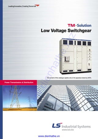
- 1. Power Transmission & Distribution Low Voltage Switchgear * The content of this catalogue applies only to the apparatus tested by ASTA. www.dienhathe.xyz www.dienhathe.vn
- 2. Introduction 2 Description and characteristics Basic structure 6 Technical characteristics 7 Busbars 8 Electrical components 9 Dimensions 14 Technical information 16 ASTA Certificates 18 Contents: TM-Solution, Your privileged pass for technology and key for solution of LV switchgear. With the TM-Solution, LS Industrial Systems proposes high-performance technical solutions to produce low voltage switchgear up to 6300A (type test completed up to 2500A).www.dienhathe.xyz www.dienhathe.vn
- 3. Simple & Easy TM-Solution is simple and easy, and can be expanded in modules of 200 mm in all 3 dimensions. That gives panel sizes of 200/400/600/800 mm etc. in width - height - depth. Advanced & Newest TM-Solution is the most advanced and newest of all the modular systems existing in the market. We are constantly developing and type testing the system & components. Full type tested by ASTA (7 type tests) Fully type tested TM-Solution according to IEC standard 60439-1 by ASTA would be the superior technology in your market. www.dienhathe.xyz www.dienhathe.vn
- 4. Modular structure TM-Solution can quickly be changed in size and layout during and after construction. Also, it can be constructed as strong as you want them by adding the standard crossbars - separation plates internally. The components can simply be re-arranged in the manner you want and it will save your time and cost. Low Voltage Switchgearwww.dienhathe.xyz www.dienhathe.vn
- 5. Open system - absolutely flexible TM-Solution is total open system, meaning that you can design the panel board the way that the engineer wants, such as front and rear access, and busbars in the rear, top and bottom. Low cost solution TM-Solution enables the panel builder to offer the end- user a low cost solution as well as the most advanced solution. Design software EPD TM-Solution is supported by free software EPD which enables you to design a panel board within minutes. It automatically generates prices, bill of material, temperature rise calculation and drawings. Drawings generated in EPD can be exported to Auto Cad. www.dienhathe.xyz www.dienhathe.vn
- 6. 6 Basic structure TM-Solution gives panel sizes of 200/400/600/800 mm etc. in width - height - depth. The system is modular in steps of 200 mm in all three directions. The cross bars can be used inside the panel in all directions. TM-Solution can be constructed as strong as you want them by adding the standard crossbars. Separation plates are used for internal partitioning. They can be assembled horizontally, vertically or longitudinally in the Techno Module structure. You can design the panel board the way that the engineer wants, like front access / rear access / bus bar in the rear / bus bar in the top / bus bar in the bottom. The doors can be fitted left or right as required. All doors are supplied with oil and chemical resistant gasket Maximum door open is 120°. 200 400 800 200 400 400 600 200 200 200 Basic frame Front Top Side Ventilation www.dienhathe.xyz www.dienhathe.vn
- 7. Technical characteristics 7 TM-Solution 2500A TM-Solution 1600A TM-Solution 800A TM-Solution 400A TM-Solution * Impulse voltage of MCB : 4 kV 2500 A 1600 A 800 A 400 A 690 V AC 415 V AC 6 kV 8 kV 6 kV 6 kV (4 kV*) 50 Hz 50 kA / 3 sec 50 kA / 3 sec 50 kA / 1 sec 20 kA / 1 sec 50 kA / 1 sec 50 kA / 1 sec 50 kA / 1 sec 20 kA / 1 sec 105 kA peak 105 kA peak 105 kA peak 52.5 kA peak 2200 mm 2000 mm 1800 mm 2000 mm 2200 mm 1800 mm 2000 mm 1200 mm 800 mm 800 mm 600 mm 300 mm 2×10×100 mm 2×10×60 mm 2×10×20 mm 2×10×10 mm 2×10×40 mm 2×10×60 mm 2×10×20 mm 2×10×10 mm Copper Indoor in dry conditions or in moderate humidity levels and factors of air pollution("Normal operating conditions" as in IEC 60439-1) 4b 3b IP 42 ASTA Type-tested switchgear assemblies in accordance with IEC 60439-1 Rated current (In max) at 40°C Rated insulation voltage, busbars (Ui) Rated operating voltage (Ue) Rated impulse withstand voltage (Uimp) Frequency Rated Short-time withstand current (Icw) Main horizontal busbars Vertical busbars_outgoing Rated peak withstand current External dimensions Height Width Depth Busbars size Main horizontal busbars Vertical busbars_outgoing Busbars material Installation Forms according to IEC 60439-1 Degree of protection according to IEC 60529 Test certificates Standard Type H W D www.dienhathe.xyz www.dienhathe.vn
- 8. 8 Busbars Busbars are used to carry electrical power throughout the switchboard. Each switchboard includes two types of busbars: ■ the main busbars ■ the distribution busbars. They are connected to the switchboard frame via insulated supports tested for their temperature-withstand capacity and non-propagation of flame characteristics. The connection between the main busbars and the droppers are made with "horizontal to vertical connectors" They are available in different sizes according to the number of main busbars and the current. The universal busbar holder can be adjusted to hold many different sizes of busbars. Busbar holder Busbar connections www.dienhathe.xyz www.dienhathe.vn
- 9. 9 Electrical components The switchgear components contained in the columns are installed on mounting plates. The combination of a mounting plate with switchgear components is called a "functional unit". Functional units are defined by standard IEC 60439-1 as a part of a low- voltage switchgear and controlgear assembly including all the electrical and mechanical elements that contribute to the fulfillment of the same function. A column may contain 40 modules, each 50 mm high. Selection and layout of the electrical switchgear components are subject to a rigorous method designed to enable switchboard definition without risk of error. Susol series circuit breakers are suitable for �Protection of power distribution �Protection of motor & its control device �Controlling and disconnecting circuits Optimum technical support for �Selecting economical protection system �Guaranteed safety of the installation �Reducing the stress on components and damage �Guaranteed service continuity Premium Susol/Metasol series meets your demands for high breaking capacity, full line-up, and optimized panel size. Various accessories and connection methods are available as user- friendly features. Susol/Metasol series provides you with total solutions with an advanced trip relay for measurement, diagnosis, analysis, and communication as well as protective functions for absolute protective coordination and electric power monitoring system. www.dienhathe.xyz www.dienhathe.vn
- 10. Electrical components 10 Type Ampere frame (AF) Rated current(A) (In max) at 40℃ Setting current (A) Control trip relay ( ... × In max) Rated current of neutral pole (A) Rated insulation voltage(V) (Ui) Rated operating voltage(V) (Ue) Rated impulse withstand voltage (kV)(Uimp) Frequency (Hz) Number of poles (P) Rated breaking capacity (kA sym) IEC 60947-2 220V/230V/380V/415V AC 50/60Hz (Icu) KS C 4620 460V/480V/500V 550V/600V/690V Rated service breaking capacity (kA) (Ics) ... %×Icu Rated making capacity (kA peak) IEC 60947-2 220V/230V/380V/415V AC 50/60Hz (Icm) KS C 4620 460V/480V/500V 550V/600V/690V Rated short-time 1 sec withstand current (kA) (Icw) 2 sec 3 sec Operating time (ms) Maximum total breaking time Maximum closing time Life cycle (time) Mechanical Without maintenance With maintenance Electrical Without maintenance With maintenance Connections Draw-out / Fixed Horizontal connection Vertical connection Front connection Mixed connection Weight (kg) Draw-out type Main body Motor charging type (3P/4P) (With cradle) Manual charging type Cradle only Fixed type Motor charging type Manual charging type External dimensions (mm) Draw-out 3P (H×W×D) type 4P Fixed type 3P 4P Trip relay Certificate & Approval Marine clasiflcation * Refer to trip relay specification. ** �: Standard, �: Option H W D * ** AN-06D AN-08D AN-10D AN-13D AN-16D AS-20D 630 800 1000 1250 1600 2000 200 400 400 630 1000 1250 1600 2000 630 800 (0.4 ~ 1.0) × In max 400 400 630 1000 1250 1600 2000 630 800 1000 690 12 50/60 3, 4 65 70 65 70 50 65 100% 100% 143 154 143 154 105 143 50 65 42 55 36 50 40 80 20,000 30,000 5,000 10,000 � - � � � - � - 63/74 70/85 61/72 68/83 29/32 33/40 34/44 38/47 32/42 36/45 430×334×375 430×419×375 300×300×295 300×385×295 N, A, P type KS / KEMA / KERI / GOST LR, ABS, DNV, KR, BV, GL, RINA, NK www.dienhathe.xyz www.dienhathe.vn
- 11. 11 Metasol ACB - AN, AS series AS-20E AS-25E AS-32E AS-40E AS-50F AS-40G AS-50G AS-63G 2000 2500 3200 4000 4000 5000 4000 5000 6300 630, 800 1000, 1250 2500 3200 4000 4000 5000 4000 5000 6300 1600, 2000 (0.4 ~ 1.0) × In max (0.4 ~ 1.0) × In max (0.4 ~ 1.0) × In max 630, 800 1000, 1250 2500 3200 4000 4000 5000 4000 5000 6300 1600, 2000 1,000 1000 1,000 690 690 690 12 12 12 50/60 50/60 50/60 3, 4 3, 4 3, 4 85 100 120 85 100 120 85 85 100 100% 100% 100% 187 220 264 187 220 264 187 187 220 85 85 100 75 75 90 65 65 85 40 40 40 80 80 80 15,000 10,000 10,000 20,000 15,000 15,000 5,000 2,000 2,000 10,000 5,000 5,000 � � � � � � � � � - - - � - - - 87/103 104/147 145/173 181/223 186/230 85/101 102/145 143/171 179/221 184/228 44/50 58/70 78/90 97/117 102/124 44/55 63/100 76/94 98/123 103/130 42/53 61/98 74/92 96/121 101/128 430×412×375 460×629×375 460×785×375 430×527×375 460×799×375 460×1015×375 300×378×295 300×597×295 300×751×295 300×493×295 300×767×295 300×981×295 N, A, P type N, A, P type N, A, P type KS / KEMA / KERI / GOST KS / KEMA / KERI / GOST KS / KEMA / KERI / GOST LR, ABS, DNV, KR, BV, GL, RINA, NK LR, ABS, DNV, KR, BV, GL, RINA, NK LR, ABS, DNV, KR, BV, GL, RINA, NK www.dienhathe.xyz www.dienhathe.vn
- 12. Electrical components 12 ♣ Applicable to MCCBs equipped with FTU, FMU, ATU ★ 2 pole MCCB in 3pole frame size ★★ 700A only available for TS800FTU TS100 TS160 100 40, 50, 63, 80, 100 2★ , 3, 4 690 500 8 750 N H L 100 120 200 50 85 150 50 70 130 42 65 85 10 15 20 50 85 100 50 85 100 100% 100% 100% 100 3 690 N H L 50 85 150 ● ● ● 100 100 2, 3, 4 690 500 2.8 2000 2000 690 W H D - - - 105 160 86 140 160 86 MCCBs for power distribution Frame size [AF] Rated current, In ♣ [A] No. of poles Rated operational AC [V] voltage, Ue DC [V] Rated impulse withstand voltage, Uimp [kV] Rated insulation voltage, Ui [V] Rated ultimate short-circuit breaking capacity, Icu AC 50/60Hz 220/240V [kA] 380/415V [kA] 440/460V [kA] 480/500V [kA] 660/690V [kA] DC 250V [kA] DC(2poles in series) 500V [kA] Rated service breaking capacity, Ics [%Icu] MCCBs for motor protection Frame size [AF] Poles Operational voltage, Ue [V] Breaking capacities Icu at 380/415V [kA] Trip unit Magnetic only Switch-disconnectors Rated thermal current, Ith [A] Rated operational current, Ie [A] Poles Operational voltage, Ue AC 50-60Hz [V] DC [V] Rated short-circuit making capacity, Icm [kA peak] Rated short-time 1s [A rms] withstand current, Icw 3s [A rms] 20s [A rms] Basic dimensions 1-pole [mm] front connection 3-pole [mm] 4-pole [mm] 160 100, 125, 160 2★ , 3, 4 690 500 8 750 N H L 100 120 200 50 85 150 50 70 130 42 65 85 10 15 20 50 85 100 50 85 100 100% 100% 100% 160 3 690 N H L 50 85 150 ● ● ● 160 160 2, 3, 4 690 500 3.6 2500 2500 960 W H D - - - 105 160 86 140 160 86 www.dienhathe.xyz www.dienhathe.vn
- 13. 13 Susol MCCB - TS series TS250 TS400 TS630 TS800 250 400 630 800 125, 160, 200, 250 300, 400 500, 630 700★★ , 800 2★ , 3, 4 2★ , 3, 4 2★ , 3, 4 2★ , 3, 4 690 690 690 690 500 500 500 500 8 8 8 8 750 750 750 750 N H L N H L N H L N H L 100 120 200 100 120 200 100 120 200 100 120 200 50 85 150 65 85 150 65 85 150 65 100 150 50 70 130 65 85 130 65 85 130 65 100 130 42 65 85 42 65 85 42 65 85 42 85 100 10 15 20 10 20 35 10 20 35 10 20 35 50 85 100 50 85 100 50 85 100 50 85 100 50 85 100 50 85 100 50 85 100 50 85 100 100% 100% 100% 100% 100% 100% 100% 100% 100% 100% 100% 100% 250 400 630 800 3 3 3 3 690 690 690 690 N H L N H L N H L N H L 50 85 150 65 85 150 65 85 150 65 100 150 ● ● ● ● ● ● ● ● ● ● ● ● 250 400 630 800 250 400 630 800 2, 3, 4 2, 3, 4 2, 3, 4 2, 3, 4 690 690 690 690 500 500 500 500 4.9 7.1 8.5 12 3500 5000 6300 8000 3500 5000 6300 8000 1350 1930 2320 2560 W H D W H D W H D W H D - - - - - - - - - - - - 105 160 86 140 260 110 140 260 110 210 320 135 140 160 86 185 260 110 185 260 110 280 320 135 www.dienhathe.xyz www.dienhathe.vn
- 14. Dimensions 14 Busbar Chamber Busbar Chamber Busbar Chamber Busbar Chamber Busbar Chamber 2F1F 1F1 2F1 3F1 5F1 5F2 5F3 5F4 5F5 5F6 4F1 1F2 3F2 1F3 3F3 1F4 3F4 3F 4F 5F 2500A ACB INCOMMER 1200A FEEDER MP 4.8 FTM 4.4 FTM 4.2 FTM 4.2 FTM 4.2 Mp 4.4 CableChamber 400A MCCB OUTGOING 250A MCCB OUTGOING 160A MCCB OUTGOING 100A MCCB OUTGOING 630A MCCB OUTGOING 400400 400400200200200600200 800600100 800 200 400 400 400 25 400 400 1002200 25 800 TM-Solution 2500A Busbar Chamber Busbar Chamber Busbar Chamber CableChamber 1F 1F1 1F2 1F3 2F1 2F 3F 3F1 3F2 3F3 3F4 3F5 200400800400200100 600 600 600 200200200200400600200 1600A ACB INCOMMER 630A MCCB OUTGOING 400A MCCB OUTGOING 250A MCCB OUTGOING 160A MCCB OUTGOING 100A MCCB OUTGOING 600 800 2000 400400 25 TM-Solution 1600A Front - view Side - view Front - view Side - view www.dienhathe.xyz www.dienhathe.vn
- 15. 15 600 400 400 400 400 60025 1800100 200 200 200400800 800A 630A Incommer Feeder Spare Spare Spare Spare Spare Spare 400200 1F1 1F2 1F3 1F4 2F1 4F1 5F1 5F2 4F2 4F3 4F4 4F5 4F6 4F7 2F2 2F3 2F4 CableChamber 1F 2F 3F 4F 5F Busbar Chamber TM-Solution 800A 1200 450 450 400 401 100 175 2000 150 400600 400400 400 300 30025 CT Insert Meter Compartment 400A MCCB 6A TS 400W TS 400W TS 400W MCCB MCCB MCCB MCCB MCCB 10A 20A 18A 30A 100A 250A TM-Solution 400A Front - view Side - view Front - view with doors Front - view with doors Side - view www.dienhathe.xyz www.dienhathe.vn
- 16. 16 IEC 60439-1 international standard (2004-04) Technical information A guarantee of quality Electrical switchboards fulfill a vital function in a company’s operations. They must be perfectly suited to the user’s needs and take full advantage of the manufacturer’s know-how, based on years of experience. National and international standards lay down the definitions and essential characteristics of switchboards, as well as the related tests. The aim of the standards is also to facilitate communication between users and manufacturers, enabling users to choose the equipment best suited to their applications. The standard The international standard that serves as a reference in this field is IEC standard 60439-1. It is reproduced, in each country, by a locally applicable standard. The various tests specified by IEC standard 60439-1 The tests designed to check the characteristics of an assembly consist of: ■ type tests, carried out on typical enclosures ■ routine tests, carried out on all new enclosures, after erection. 7 type tests Verification of temperature-rise limits The conditions specified for carrying out tests are as close as possible to normal operating conditions. For the test to be as representative as possible, the main busbars, distribution busbars and circuits are supplied with their test current. The test is considered to be satisfactory if the observed (or determined) temperature rise does not exceed the values specified in the standard and the switchgear or components retain their normal operating characteristics. Verification of the dielectric properties The value of the test voltage is a function of the rated insulation voltage. It is defined by the standard. The test is considered to be satisfactory if there is no unintentional disruptive discharge during the tests. Verification of short-circuit withstand strength The test conditions depend on: ■ the rms short-circuit current value ■ the prescribed time (1 second, unless otherwise specified) ■ the peak short-circuit current value. Relation between the peak short-circuit current value and the rms value: I peak = I rms x n (asymmetry coefficient). The test is considered to be satisfactory if the mechanical and dielectric properties of the equipment still meet the requirements of the standard. Temperature-rise test Dielectric test I rms Cosφ n I ≤ 5 kA 0.7 1.5 5 kA < I ≤ 10 kA 0.5 1.7 10 kA < I ≤ 20 kA 0.3 2 20 kA < I ≤ 50 kA 0.25 2.1 I > 50 kA 0.2 2.2 www.dienhathe.xyz www.dienhathe.vn
- 17. 17 Verification of the effectiveness of the protective circuit The test checks the effective connection between the exposed conductive parts and the protective circuit. It also checks the short-circuit withstand capacity of the protective circuit. The test is considered to be satisfactory if the mechanical and electrical properties of the equipment still meet the requirements of the standard. Verification of clearances and creepage distances The test is considered to be satisfactory if the distances still meet the requirements of the standard, particularly in the event of possible deformation of the enclosures or barriers as well as all the positions of withdrawable parts (disconnection, test). Verification of mechanical operation The test involves performing 50 operating cycles on specific mechanisms on the switchboard (disconnection, locking of drawers, etc.). The test is considered to be satisfactory if the operation of these mechanisms is not impaired and the same force is required as before the test. Verification of the degree of protection The obtained degree of protection must comply with IEC standard 60529, after appropriate adaptations to the particular type of assembly if required. The test reports The test centre report contains: ■ identification of the centre, manufacturer and tested assembly ■ main characteristics of the assembly ■ references of the standards applied for the tests ■ results obtained and the observations made during and after the tests ■ documents (records, drawings, photographs, etc.). Degrees of protection External influences Several national and international standards have classified a number of external influences to which an electrical installation can be exposed, for example the ingress of solid foreign bodies and water. Degree of protection Standard IEC 60529 defines IP numbers used to quantify the degree of protection provided by enclosures against: ■ ingress of solid foreign bodies (first number) ■ ingress of water (second number). Short-circuit withstand test Degree of protection test www.dienhathe.xyz www.dienhathe.vn
- 18. ASTA Certificates 18 TM-Solution 2500A TM-Solution 1600A www.dienhathe.xyz www.dienhathe.vn
- 20. ��For your safety, please read user's manual thoroughly before operating. ��Contact the nearest authorized service facility for examination, repair, or adjustment. ��Please contact qualified service technician when you need maintenance. Do not disassemble or repair by yourself! ��Any maintenance and inspection shall be performed by the personnel having expertise concerned.Safety Instructions www.lsis.biz ��LS Industrial Systems (Middle East) FZE ����Dubai, U.A.E. Address: LOB 19 JAFZA VIEW TOWER Room 205, Jebel Ali Freezone P.O. Box 114216, Dubai, United Arab Emirates Tel: 971-4-886 5360 Fax: 971-4-886-5361 e-mail: hwyim@lsis.biz ��Dalian LS Industrial Systems Co., Ltd. ����Dalian, China Address: No.15, Liaohexi 3-Road, Economic and Technical Development zone, Dalian 116600, China Tel: 86-411-8273-7777 Fax: 86-411-8730-7560 e-mail: lixk@lsis.com.cn ��LS Industrial Systems (Wuxi) Co., Ltd. ����Wuxi, China Address: 102-A , National High & New Tech Industrial Development Area, Wuxi, Jiangsu, 214028, P.R.China Tel: 86-510-8534-6666 Fax: 86-510-522-4078 e-mail: xuhg@lsis.com.cn ��LS-VINA Industrial Systems Co., Ltd. ����Hanoi, Vietnam Address: Nguyen Khe - Dong Anh - Ha Noi - Viet Nam Tel: 84-4-882-0222 Fax: 84-4-882-0220 e-mail: srjo@lsisvina.com ��LS-VINA Industrial Systems Co., Ltd. ����Hochiminh , Vietnam Address: 41 Nguyen Thi Minh Khai Str. Yoco Bldg 4th Floor, Hochiminh City, Vietnam Tel: 84-8-3822-7941 Fax: 84-8-3822-7942 e-mail: sbpark@lsisvina.com ��LS Industrial Systems Tokyo Office ����Tokyo, Japan Address: 16FL, Higashi-Kan, Akasaka Twin Tower 17-22, 2-chome, Akasaka, Minato-ku Tokyo 107-8470, Japan Tel: 81-3-3582-9128 Fax: 81-3-3582-2667 e-mail: jschuna@lsis.biz ��LS Industrial Systems Shanghai Office ����Shanghai, China Address: Room E-G, 12th Floor Huamin Empire Plaza, No.726, West Yan'an Road Shanghai 200050, P.R. China Tel: 86-21-5237-9977 (609) Fax: 89-21-5237-7191 e-mail: jinhk@lsis.com.cn ��LS Industrial Systems Beijing Office ����Beijing, China Address: B-Tower 17FL.Beijing Global Trade Center B/D. No.36, BeiSanHuanDong-Lu, DongCheng-District, Beijing 100013, P.R. China Tel: 86-10-5825-6025,7 Fax: 86-10-5825-6026 e-mail: cuixiaorong@lsis.com.cn ��LS Industrial Systems Guangzhou Office ����Guangzhou, China Address: Room 1403,14F,New Poly Tower,2 Zhongshan Liu Road,Guangzhou, P.R. China Tel: 86-20-8326-6764 Fax: 86-20-8326-6287 e-mail: linsz@lsis.biz ��LS Industrial Systems Chengdu Office ����Chengdu, China Address: 12Floor, Guodong Building, No52 Jindun Road Chengdu, 610041, P.R. China Tel: 86-28-8612-9151 Fax: 86-28-8612-9236 e-mail: yangcf@lsis.com.cn ��LS Industrial Systems Qingdao Office ����Qingdao, China Address: 7B40,Haixin Guangchang Shenye Building B, No.9, Shandong Road Qingdao 26600, P.R. China Tel: 86-532-8501-6568 Fax: 86-532-583-3793 e-mail: lirj@lsis.com.cn �� HEAD OFFICE LS Tower 1026-6, Hogye-dong, Dongan-gu, Anyang-si, Gyeonggi-do 431-848, Korea Tel. (82-2)2034-4901/4942~3 Fax. (82-2)780-0382 e-mail. bonseongk@lsis.biz http://www.lsis.biz �� Global Network Specifications in this catalog are subject to change without notice due to continuous product development and improvement. 2009. 01 Low Voltage Distribution Panel 2008. 11/(02) 2009. 01 Printed in Korea STAFF ⓒ 2008.11 LS Industrial Systems Co.,Ltd. All rights reserved. www.dienhathe.xyz www.dienhathe.vn