SlideShare une entreprise Scribd logo
1  sur  69
The general principle states that the effect of a force acting on a rigid body does not
change if the force is moved along its line of action to another point on the body.
In clear, the point of application of a force can be moved anywhere along its line of
action without changing the external reaction forces on a rigid body.
Any force that has the same magnitude and direction, and which has a point of
application somewhere along the same line of action will cause the same acceleration
and will result in the same moment.
Therefore, the points of application of forces may be moved along the line of action to
simplify the analysis of rigid bodies.
Principle of transmissibility of a force
The main thing to be noted is when analyzing
the internal forces (stress) in a rigid body, the
exact point of application does matter.
This difference in stresses may also result in
changes in geometry which will may in turn
affect reaction forces. For this reason, the
principle of transmissibility should only be
used when examining external forces on
bodies that are assumed to be rigid.
Limitation of principle of transmissibility: Principle of transmissibility can be used
only for rigid bodies and cannot be used for deformable bodies.
The Principle Of Superposition states that when two waves of the
same kind meet at a point in space, the resultant displacement at that point is the
vector sum of the displacements that the two waves would separately produce at
that point.
Net effect of forces applied in any sequence on a body is given by the algebraic sum
of effect of individual forces on the body
Assumptions made in Engineering Mechanics
i) All bodies are RIGID.
ii) PARTICLE concept can be used wherever applicable.
iii) PRINCIPLE OF PHYSICAL INDEPENDENCE of forces is valid.
iv) PRINCIPLE OF SUPERPOSITION of forces is valid.
v) PRINCIPLE OF TRANSMISSIBILITY of forces is valid.
SYSTEM OF FORCES
A group or set of forces is called system of forces.
Coplanar force system: If all the forces in the
system lie in a single plane, it is called
coplanar force system.
Concurrent force system: If line of action of all
the forces in a system passes through a single
point it is called concurrent force system.
Collinear force system: In a system, all the
forces parallel to each other, if line of action
of all forces lie along a single line then it is called a
collinear force system.
Concurrent force system: If the line of action of
forces forming the system pass through a common
point (point of concurrence) then the system is
said to be concurrent.
Non-concurrent force system : f the lines of
action of forces forming the system do not pass
through a common point, then the system is said
to be non-concurrent.
Parallel force system :It is a particular case of non-
concurrent force system in which the line of
action of forces forming the system are parallel.
COMPOSITION OF FORCES
Composition of Forces or compounding is the method to find resultant force of
a number of forces acting simultaneously on a body.
Methods for finding resultant force(FR) are
• Parallelogram Law
• Triangle Law
• Polygon law
• Resolution of forces or Method of Resolution
GRAPHICAL METHOD
In Graphical method, forces are drawn on graph with some suitable scale and their
resultant is measured by Parallelogram law, Triangle Law or Polygon Law.
While Parallelogram law is also used as analytical method for resolution of forces.
Let’s study the laws used for graphical method for composition of forces.
• Parallelogram Law
• Triangle Law
• Polygon law
PARALLELOGRAM LAW OF FORCES
“If two consecutive sides of a parallelogram represents the magnitude
and direction of two coplaner forces acting on a particle, then its
diagonal represents the Resultant Force(FR) in magnitude and
direction.”
Consider two vectors P⃗ and Q⃗
as shown in the figure. Vector Q⃗ is displaced parallel to itself till the tail end of both the vectors touch at
a point O.
The parallelogram is completed as shown in the figure. Applying the law of triangle of vectors, to the
triangle OAC, we have,
OA + AC = OC
or P⃗ + Q⃗ = R⃗
→ → →
Two forces F1 and F2 of magnitudes 80KN and 50KN respectively acting simultaneously on a particle such that
the angle between the two forces is 60o. Considering bigger force as F1.
Taking some suitable scale and drawing a
parallelogram ABCD with Sides AB and AD
representing the forces F1 and F2 and having an
angle (θ) between them.
F1 as AB = 80 mm = 8 cm,
F2 as AD = 50 mm = 5 cm
θ = 60o
According to law of parallelogram diagonal AC is representing
the resultant force (FR). Length of the diagonal AC is the
magnitude of the resultant force and the angle (α), which
diagonal AC is making with the side AB, represents the
direction of resultant force (FR).
By Measurement
Thus the Resultant FR is equal to 113.5 KN acting at an angle (α) 22.5o with F1.
TRIANGLE LAW OF FORCES
“If two sides of a triangle, taken in order, represents the magnitude and direction of
two coplaner forces acting on a partical, then its third side, taken in opposite order
represents the Resultant Force(FR) in magnitude and direction.”
Taking some suitable scale (1KN = 1 mm)
drawing a triangle ABC with sides AB and BC
representing the forces F1 and F2 and having an
angle (θ) between BC and extended side AB
F1 as AB = 80 mm = 8 cm,
F2 as BC = 50 mm = 5 cm
θ = 60o
According to triangle law of forces side AC is representing the resultant force (FR).
Length of side AC is the magnitude of the resultant force and the angle (α), which
side AC is making with side AB represents the direction of resultant force (FR).
By Measurement
Triangle and parallelogram law are best suited for system of forces
having two forces acting simultaneously on a body. For a system of
forces having more than two forces, Polygon law of forces is applied.
Thus the Resultant FR is equal to 113.5 KN
acting at an angle (α) 22.5o with F1.
POLYGON LAW OF FORCE
“If sides of a polygon, taken in order, represents the magnitude and direction of more
than two coplaner forces, acting on a partical, then its closing side, taken in opposite
order, represents the Resultant Force(FR) in magnitude and direction.”
Let us consider a system of forces F1, F2, F3 & F4. Having magnitude as 25 KN, 35 KN, 30
KN & 20 KN, making an angle of 30o, 45o, 40o and 80o with horizontal
Taking some suitable scale (1KN = 1 mm) drawing the sides of
polygon ABCDE with Sides AB, BC, CD & DE representing the
forces F1, F2, F3 & F4, having respective angle between them.
Joining point A and E to draw the closing side AE.
F1 as AB = 25 mm = 2.5 cm,
F2 as BC = 35 mm = 3.5 cm
F3 as CD = 30 mm = 3 cm,
F4 as DE = 20 mm = 2 cm
Angle between F1 and F2 is 105o
Angle between F2 and F3 is 95o
A
B
C
D
E
F1 as AB = 25 mm = 2.5 cm,
F2 as BC = 35 mm = 3.5 cm
F3 as CD = 30 mm = 3 cm,
F4 as DE = 20 mm = 2 cm
A B
B C
C D
D E
Rotate 330Original
According to polygon law of forces, side AE is representing the resultant force (FR).
Length of side AE is the magnitude of the resultant force and the angle (α) which
side AE is making with side AB represents the direction of resultant force (FR).
Thus the Resultant FR is equal to 22.6 KN acting at an angle (α)
154.4o with F1.
ANALYTICAL METHOD
Analytical method is different from graphical method. Let us study
analytical method for finding the resultant force for number of forces
acting simultaneously on a particle. There are two analytical methods
for composition of forces, Parallelogram law and Method of
Resolution.
PARALLELOGRAM LAW OF FORCES
“If two consecutive sides of a parallelogram represents the magnitude
and direction of two coplaner forces acting on a partical,
Then the Resultant Force (FR) and angle α is obtained by
Solving Illustration 1 by parallelogram law
Resultant Force FR will be
The angle (α) which resultant FR is making with force F1
RESOLUTION OF FORCES FOR RESULTANT FORCE
Before understanding the method of finding resultant force by method
of Resolution let us understand what resolution of forces is.
Resolution of Forces
Resolution of forces is the process of breaking a force into two components, basically horizontal and
vertical components.
Suppose force (F) acting on a particle such that, it is making an angle (θ) with horizontal axis (AB).
Horizontal Component
It is the product of magnitude of force and the cosine
of the angle, it is making with horizontal axis.
Direction of the component is considered same as
the direction of horizontal axis, with which it is
making the angle θ.
Vertical Component
It is the product of magnitude of force and the sine of
the angle, it is making with horizontal axis. Direction
of the component is considered same as the direction
of vertical axis, normal to the horizontal axis with
which it is making the angle θ.
PRINCIPLE OF FINDING RESULTANT FORCE BY THE METHOD OF
RESOLUTION OF FORCES
“The resolved parts of the forces in a particular direction will be equal to the
resolved parts of resultant force in same direction.”
Method of resolution of forces starts with summation of Horizontal Components in
a system of forces is represented By ∑H while summation of Vertical Components is
represented by ∑V.
∑H = Sum of Horizontal Components in a system of forces.
= F1cos θ1 + F2cos θ2 + F3cos θ3 +_ _ _+ Fn cos θn
∑V = Sum of Vertical Components in a system of forces.
= F1sin θ1 + F2sin θ2 + F3sin θ3 +_ _ _+ Fn sin θn
Direction of resultant in terms of angle(α) is obtained by
Magnitude of resultant force is obtained by
Solving Illustration 2 with method of resolution
Evaluating ∑H and ∑V (Using sign convention)
∑H = 25 cos 30o + 20 cos 80o + (-30 cos 40o) + (-35 cos 45o)
= 25 cos 30o + 20 cos 80o – 30 cos 40o – 35 cos 45o
= – 22.60
∑H = – 22.60 (-ve)
Similarly
∑V = 25 sin 30o + 35 sin 45o + (- 30 sin 40o) + (- 20 sin 80o)
= 25 sin 30o + 35 sin 45o – 30 sin 40o – 20 sin 80o
= – 1.73
∑V = – 1.73 (-ve)
Resultant Force FR
Resultant Force FR
The angle (α), which resultant (FR) making with horizontal axis.
In Solution of illustration 2 by polygon law, α is the angle which resultant FR is making
with force F1. Here α is the angle, which resultant FR is making with horizontal axis in
negative direction.
Thus angle between FR and F1 will be
Thus sum of both horizontal and vertical
Component of forces is negative, the
resultant will lie in 3rd quadrant.
Two forces 5 N and 20 N are acting at an angle of 120
degree between them . Find the resultant force in
magnitude and direction.
When vectors act as maximum and minimum?
Solution : It is to be noted that the magnitude of the resultant of two vectors is maximum , when the vectors
act in the same direction and is minimum when they act in opposite directions.
Two forces 10 N and 14 N are acting upon the a body . What
can be the maximum and minimum resultant force on the body
?
Two forces 5 N and 20 N are acting at an angle of 120
degree between them . Find the resultant force in
magnitude and direction.
Two forces 10 N and 14 N are acting upon the a body . What
can be the maximum and minimum resultant force on the body
?
Two forces 5 N and 20 N are acting at an angle of 120
degree between them . Find the resultant force in
magnitude and direction.
Two forces 10 N and 14 N are acting upon the a body . What
can be the maximum and minimum resultant force on the body
?
Drawing Free-Body Diagrams
Free-body diagrams are diagrams used to show the relative
magnitude and direction of all forces acting upon an object in a
given situation.
1. The size of the arrow in a free-body diagram reflects the
magnitude of the force.
2. The direction of the arrow shows the direction that the force is
acting.
3. Each force arrow in the diagram is labelled to indicate the exact
type of force.
It is generally customary in a free-body diagram to represent the
object by a box and to draw the force arrow from the centre of the
box outward in the direction that the force is acting
Force Symbol Magnitude Direction
Gravity (weight) F(G) = mobject*g (9.8 m/s2) Downward
Normal (surface) F(N) any (up to breaking load) perpendicular to surface
Tension F(T) any (up to breaking load) along string/rope/chain
Friction F(fr)
not slipping: between zero
and ms*F(N)
slipping: = mk*F(N)
Direction opposing relative
motion.
Horizontal Component
It is the product of magnitude of force and the cosine
of the angle, it is making with horizontal axis.
Direction of the component is considered same as
the direction of horizontal axis, with which it is
making the angle θ.
Vertical Component
It is the product of magnitude of force and the sine of
the angle, it is making with horizontal axis. Direction
of the component is considered same as the direction
of vertical axis, normal to the horizontal axis with
which it is making the angle θ.
•A book is at rest on a tabletop. Diagram the forces
acting on the book.
•A girl is suspended motionless from the ceiling by
two ropes. Diagram the forces acting on the
combination of girl and bar..
A book on a table
In this example, there are two forces acting on a book at rest on a table:
1) The weight W exerted by the earth on the book
2) The normal force N exerted by the table on the book.
A suspended block
In this example, there are two forces acting on the suspended block at rest:
1) The weight W exerted by the earth on the block
2) The tension force T exerted by the string (or rope) on the block.
A block on a floor with an acting force Fa to pull the block
In this example, the block is being pulled and therefore a force
of friction acts on the block. So there are four forces acting on
the block.
1) The weight W exerted by the earth on the block
2) The normal force N exerted by floor on the block.
3) The acting force Fa to pull the block.
4) The force of friction Ff exerted by floor on the block in the
direction opposite the motion due to Fa.
A falling object
In this example, there is only one force action on the falling object.
1) The weight W exerted by the earth on the falling object.
A falling object with Air Friction
here only two force action on the falling object.
1) The weight W exerted by the earth on the falling object.
2) The Friction FAir
An box on an incline plane (with no frictions)
In this example, we assume that the inclined plane is frictionless;
two forces act on the box:
1) The weight W exerted by the earth on the box.
2) The normal force N exerted by the inclined plane on the box.
N is normal to the inclined plane.
An box on an incline plane with an acting force
and friction considered.
In this example, a force Fa pulls the box upward
and frictions are not negligible. Four forces act on
the box:
1) The weight W exerted by the earth on the box.
2) The normal force N exerted by the inclined plane
on the box. N is normal to the inclined plane.
3) The acting force Fa.
4) The force of friction Fs exerted by the inclined
plane on the box in the direction opposite the
motion due to Fa.
A block suspended to the ceiling using three strings.
A) free body diagram for the block; two forces (lower part
of figure below)
1) The weight W exerted by the earth on the box.
2) The tension force T '3 exerted by the string on the block.
B) free body diagram of point P; three forces (upper part of
figure below)
1) Tension T1
2) Tension T2
3) Tension T3
A system with two blocks, an inclined plane and a pulley.
A) free body diagram for block m1 (left of figure below)
1) The weight W1 exerted by the earth on the box.
2) The normal force N
3) The force of friction Fk
4) The tension force T exerted by the string on the block m1.
B) free body diagram of block m2 (right of figure below)
1) The weight of the block W2
2) Tension T '.
Determining the Net Force
In the statement of Newton's first law, the unbalanced force refers to that force that
does not become completely balanced (or canceled) by the other individual forces. If
either all the vertical forces (up and down) do not cancel each other and/or all
horizontal forces do not cancel each other, then an unbalanced force exists. The
existence of an unbalanced force for a given situation can be quickly realized by looking
at the free-body diagram for that situation. Free-body diagrams for three situations are
shown below. Note that the actual magnitudes of the individual forces are indicated on
the diagram.
Free-body diagrams for four situations are shown below. The net force is known for each situation.
However, the magnitudes of a few of the individual forces are not known. Analyze each situation
individually and determine the magnitude of the unknown forces.
The force F is producing, simultaneous
x displacement and y-displacement.
The part of the force F which is
producing x displacement is called x
component or horizontal component of
the force F(Fx). The part of the force F
which produces y – displacement is
called y component of the force or
vertical component of force F(Fy).
The technique of finding a component of a force along any direction is called
resolution of force. The component of a force along any direction is called the
resolved component. The components of a force determined along two mutually
perpendicular direction are called rectangular components.
RESOLUTION OF A FORCE
In the diagram the force F is resolved into two perpendicular
component forces that is the Fy and Fx components (using
parallelogram method).
To calculate the magnitude of the vertical (Fy) and
horizontal (Fx) forces, we can use simple trigonometry.
Fx = F cos θ , Since cos θ = (Fx/F)
Fy = F sin θ, Since sin θ = (Fy/ F)
Horizontal Component
It is the product of magnitude of force and the cosine
of the angle, it is making with horizontal axis.
Direction of the component is considered same as
the direction of horizontal axis, with which it is
making the angle θ.
Vertical Component
It is the product of magnitude of force and the sine of
the angle, it is making with horizontal axis. Direction
of the component is considered same as the direction
of vertical axis, normal to the horizontal axis with
which it is making the angle θ.
To calculate the magnitude of the vertical
(Fy) and horizontal (Fx) forces, we can use
simple trigonometry.
Fx = F cos θ , Since cos θ = (Fx/F)
Fy = F sin θ, Since sin θ = (Fy/ F)
Note:
1. Sign convention for the direction of components.
The horizontal component or ‘X’ component of a force acting
along x direction is the force itself. Whereas, its vertical
component or y-component is zero.
2.
‘x’ component of a force acting along Y direction is
zero. Whereas, its ‘y’ component is equal to itself.
4. If a force is inclined at 45o
w.r.t. x axis or y axis then its x component will
be equal to y component (Fx= Fy).
Principle of transmissibility of forces on rigid bodies

Contenu connexe

Tendances

INTRODUCTION TO ENGINEERING MECHANICS
INTRODUCTION TO ENGINEERING MECHANICSINTRODUCTION TO ENGINEERING MECHANICS
INTRODUCTION TO ENGINEERING MECHANICSvinaykovvuri1
 
Concurrent Forces
Concurrent ForcesConcurrent Forces
Concurrent Forcesstooty s
 
Armstrong oscillator
Armstrong oscillatorArmstrong oscillator
Armstrong oscillatorayesha zaheer
 
Engineering Mechanics First Year
Engineering Mechanics First YearEngineering Mechanics First Year
Engineering Mechanics First YearEkeeda
 
Kinetics of a Particle : Force and Acceleration
Kinetics of a Particle : Force and AccelerationKinetics of a Particle : Force and Acceleration
Kinetics of a Particle : Force and AccelerationAbduljalil AlAbidi
 
Engmech 05 (equilibrium_of_concurrent_force_system)
Engmech 05 (equilibrium_of_concurrent_force_system)Engmech 05 (equilibrium_of_concurrent_force_system)
Engmech 05 (equilibrium_of_concurrent_force_system)physics101
 
1. Resolution and composition of forces REV (2).ppt
1. Resolution and composition of forces REV (2).ppt1. Resolution and composition of forces REV (2).ppt
1. Resolution and composition of forces REV (2).pptVrushali Nalawade
 
Control system lectures
Control system lectures Control system lectures
Control system lectures Naqqash Sajid
 
(Latest) topic 5 field_effect_transistors
(Latest) topic 5 field_effect_transistors(Latest) topic 5 field_effect_transistors
(Latest) topic 5 field_effect_transistorsGabriel O'Brien
 

Tendances (20)

Lecture 8 bjt_1
Lecture 8 bjt_1Lecture 8 bjt_1
Lecture 8 bjt_1
 
INTRODUCTION TO ENGINEERING MECHANICS
INTRODUCTION TO ENGINEERING MECHANICSINTRODUCTION TO ENGINEERING MECHANICS
INTRODUCTION TO ENGINEERING MECHANICS
 
Concurrent Forces
Concurrent ForcesConcurrent Forces
Concurrent Forces
 
Chapter 2
Chapter 2Chapter 2
Chapter 2
 
Armstrong oscillator
Armstrong oscillatorArmstrong oscillator
Armstrong oscillator
 
Engineering Mechanics First Year
Engineering Mechanics First YearEngineering Mechanics First Year
Engineering Mechanics First Year
 
Kinetics of a Particle : Force and Acceleration
Kinetics of a Particle : Force and AccelerationKinetics of a Particle : Force and Acceleration
Kinetics of a Particle : Force and Acceleration
 
Deflection of beams
Deflection of beamsDeflection of beams
Deflection of beams
 
Assignment no 1
Assignment no 1Assignment no 1
Assignment no 1
 
Energy methods
Energy methodsEnergy methods
Energy methods
 
Hybrid Parameter in BJT
Hybrid Parameter in BJTHybrid Parameter in BJT
Hybrid Parameter in BJT
 
Engmech 05 (equilibrium_of_concurrent_force_system)
Engmech 05 (equilibrium_of_concurrent_force_system)Engmech 05 (equilibrium_of_concurrent_force_system)
Engmech 05 (equilibrium_of_concurrent_force_system)
 
1. Resolution and composition of forces REV (2).ppt
1. Resolution and composition of forces REV (2).ppt1. Resolution and composition of forces REV (2).ppt
1. Resolution and composition of forces REV (2).ppt
 
L07 dc and ac load line
L07 dc and ac load lineL07 dc and ac load line
L07 dc and ac load line
 
Unit 2 resonance circuit
Unit 2 resonance circuitUnit 2 resonance circuit
Unit 2 resonance circuit
 
Control system lectures
Control system lectures Control system lectures
Control system lectures
 
Complex stresses
Complex stressesComplex stresses
Complex stresses
 
(Latest) topic 5 field_effect_transistors
(Latest) topic 5 field_effect_transistors(Latest) topic 5 field_effect_transistors
(Latest) topic 5 field_effect_transistors
 
Rigid body
Rigid bodyRigid body
Rigid body
 
Lami's theorem
Lami's theoremLami's theorem
Lami's theorem
 

En vedette

Engmech 03 (resultant concurrent force system)
Engmech 03 (resultant concurrent force system)Engmech 03 (resultant concurrent force system)
Engmech 03 (resultant concurrent force system)physics101
 
Force system resultant
Force system resultantForce system resultant
Force system resultantaero103
 
Engmech 04 (resultant_nonconcurrent_force_system)
Engmech 04 (resultant_nonconcurrent_force_system)Engmech 04 (resultant_nonconcurrent_force_system)
Engmech 04 (resultant_nonconcurrent_force_system)physics101
 
Grade 11, U1B-L3, FBD's & Components
Grade 11, U1B-L3, FBD's & Components Grade 11, U1B-L3, FBD's & Components
Grade 11, U1B-L3, FBD's & Components gruszecki1
 
III - resultant of non-concurrent forces
III -  resultant of non-concurrent forcesIII -  resultant of non-concurrent forces
III - resultant of non-concurrent forcesdjpprkut
 
COPLANNER & NON-CONCURRENT FORCES
COPLANNER & NON-CONCURRENT FORCESCOPLANNER & NON-CONCURRENT FORCES
COPLANNER & NON-CONCURRENT FORCESAkash Patel
 
Coplanar concurrent forces
Coplanar concurrent forcesCoplanar concurrent forces
Coplanar concurrent forcesDarshan Panchal
 
Concurrent Forces
Concurrent ForcesConcurrent Forces
Concurrent Forcesguestb54490
 
FORCE, TYPES, & SYSTEM OF FORCES
FORCE, TYPES, & SYSTEM OF FORCESFORCE, TYPES, & SYSTEM OF FORCES
FORCE, TYPES, & SYSTEM OF FORCESManish Jha
 
Force, types of forces and system of forces
Force, types of forces and system of forcesForce, types of forces and system of forces
Force, types of forces and system of forcesKhanSaif2
 

En vedette (17)

Engmech 03 (resultant concurrent force system)
Engmech 03 (resultant concurrent force system)Engmech 03 (resultant concurrent force system)
Engmech 03 (resultant concurrent force system)
 
Force system resultant
Force system resultantForce system resultant
Force system resultant
 
Engmech 04 (resultant_nonconcurrent_force_system)
Engmech 04 (resultant_nonconcurrent_force_system)Engmech 04 (resultant_nonconcurrent_force_system)
Engmech 04 (resultant_nonconcurrent_force_system)
 
Grade 11, U1B-L3, FBD's & Components
Grade 11, U1B-L3, FBD's & Components Grade 11, U1B-L3, FBD's & Components
Grade 11, U1B-L3, FBD's & Components
 
Force
ForceForce
Force
 
III - resultant of non-concurrent forces
III -  resultant of non-concurrent forcesIII -  resultant of non-concurrent forces
III - resultant of non-concurrent forces
 
1 force sys type
1 force sys type1 force sys type
1 force sys type
 
Force system
Force systemForce system
Force system
 
COPLANNER & NON-CONCURRENT FORCES
COPLANNER & NON-CONCURRENT FORCESCOPLANNER & NON-CONCURRENT FORCES
COPLANNER & NON-CONCURRENT FORCES
 
Coplanar concurrent forces
Coplanar concurrent forcesCoplanar concurrent forces
Coplanar concurrent forces
 
Concurrent Forces
Concurrent ForcesConcurrent Forces
Concurrent Forces
 
Types of forces
Types of forcesTypes of forces
Types of forces
 
FORCE, TYPES, & SYSTEM OF FORCES
FORCE, TYPES, & SYSTEM OF FORCESFORCE, TYPES, & SYSTEM OF FORCES
FORCE, TYPES, & SYSTEM OF FORCES
 
Types of forces
Types of forcesTypes of forces
Types of forces
 
Forces Ppt
Forces PptForces Ppt
Forces Ppt
 
Texto popular
Texto popularTexto popular
Texto popular
 
Force, types of forces and system of forces
Force, types of forces and system of forcesForce, types of forces and system of forces
Force, types of forces and system of forces
 

Similaire à Principle of transmissibility of forces on rigid bodies

Lecture 4 - Resultant of Forces - Part 1.pptx
Lecture 4 - Resultant of Forces - Part 1.pptxLecture 4 - Resultant of Forces - Part 1.pptx
Lecture 4 - Resultant of Forces - Part 1.pptxMarjorieJeanAnog
 
Engineering Mechanics - Intro to Statics.pdf
Engineering Mechanics - Intro to Statics.pdfEngineering Mechanics - Intro to Statics.pdf
Engineering Mechanics - Intro to Statics.pdfYogesh Kulkarni
 
moments couples and force couple systems by ahmad khan
moments couples and force couple systems by ahmad khanmoments couples and force couple systems by ahmad khan
moments couples and force couple systems by ahmad khanSelf-employed
 
Handbook to ssc je mechanical
Handbook to ssc je mechanical Handbook to ssc je mechanical
Handbook to ssc je mechanical mechanical Singh
 
L0-T1 MOS OCT 2020.pptx .
L0-T1 MOS OCT 2020.pptx                          .L0-T1 MOS OCT 2020.pptx                          .
L0-T1 MOS OCT 2020.pptx .happycocoman
 
LECTURE NOTES ON STATICS_2024 power point presentation.
LECTURE NOTES ON STATICS_2024 power point presentation.LECTURE NOTES ON STATICS_2024 power point presentation.
LECTURE NOTES ON STATICS_2024 power point presentation.HabyarimanaProjecte
 
Mechanical Technology Grade 10 Chapter 8 forces
Mechanical Technology Grade 10 Chapter 8 forcesMechanical Technology Grade 10 Chapter 8 forces
Mechanical Technology Grade 10 Chapter 8 forcesFuture Managers
 
Engineering Mechanics.pptx
Engineering Mechanics.pptxEngineering Mechanics.pptx
Engineering Mechanics.pptxYogesh Kulkarni
 
Momento en estructuras
Momento en estructurasMomento en estructuras
Momento en estructurasRol D
 
Engineering mechanics
Engineering mechanics Engineering mechanics
Engineering mechanics Ashish Mishra
 
ENGINEERING MECHANICS UNIT 1 SPPU
ENGINEERING MECHANICS UNIT 1 SPPUENGINEERING MECHANICS UNIT 1 SPPU
ENGINEERING MECHANICS UNIT 1 SPPUShripad Deshpande
 
Resultant of Forces System.ppt
Resultant of  Forces System.pptResultant of  Forces System.ppt
Resultant of Forces System.pptPkaheesi
 
Resultant of Forces System.ppt
Resultant of  Forces System.pptResultant of  Forces System.ppt
Resultant of Forces System.pptPkaheesi
 

Similaire à Principle of transmissibility of forces on rigid bodies (20)

Lecture 4 - Resultant of Forces - Part 1.pptx
Lecture 4 - Resultant of Forces - Part 1.pptxLecture 4 - Resultant of Forces - Part 1.pptx
Lecture 4 - Resultant of Forces - Part 1.pptx
 
Engineering Mechanics - Intro to Statics.pdf
Engineering Mechanics - Intro to Statics.pdfEngineering Mechanics - Intro to Statics.pdf
Engineering Mechanics - Intro to Statics.pdf
 
Ctm 154[1]
Ctm 154[1]Ctm 154[1]
Ctm 154[1]
 
Resultant of forces
Resultant of forcesResultant of forces
Resultant of forces
 
coplanarforce[1].pptx
coplanarforce[1].pptxcoplanarforce[1].pptx
coplanarforce[1].pptx
 
moments couples and force couple systems by ahmad khan
moments couples and force couple systems by ahmad khanmoments couples and force couple systems by ahmad khan
moments couples and force couple systems by ahmad khan
 
Handbook to ssc je mechanical
Handbook to ssc je mechanical Handbook to ssc je mechanical
Handbook to ssc je mechanical
 
Forceanalysis
ForceanalysisForceanalysis
Forceanalysis
 
Applied mechanics
Applied mechanicsApplied mechanics
Applied mechanics
 
L0-T1 MOS OCT 2020.pptx .
L0-T1 MOS OCT 2020.pptx                          .L0-T1 MOS OCT 2020.pptx                          .
L0-T1 MOS OCT 2020.pptx .
 
LECTURE NOTES ON STATICS_2024 power point presentation.
LECTURE NOTES ON STATICS_2024 power point presentation.LECTURE NOTES ON STATICS_2024 power point presentation.
LECTURE NOTES ON STATICS_2024 power point presentation.
 
Mechanical Technology Grade 10 Chapter 8 forces
Mechanical Technology Grade 10 Chapter 8 forcesMechanical Technology Grade 10 Chapter 8 forces
Mechanical Technology Grade 10 Chapter 8 forces
 
Engineering Mechanics.pptx
Engineering Mechanics.pptxEngineering Mechanics.pptx
Engineering Mechanics.pptx
 
Momento en estructuras
Momento en estructurasMomento en estructuras
Momento en estructuras
 
Applied mechanics
Applied mechanicsApplied mechanics
Applied mechanics
 
MECHANICS OF SOLID
MECHANICS OF SOLIDMECHANICS OF SOLID
MECHANICS OF SOLID
 
Engineering mechanics
Engineering mechanics Engineering mechanics
Engineering mechanics
 
ENGINEERING MECHANICS UNIT 1 SPPU
ENGINEERING MECHANICS UNIT 1 SPPUENGINEERING MECHANICS UNIT 1 SPPU
ENGINEERING MECHANICS UNIT 1 SPPU
 
Resultant of Forces System.ppt
Resultant of  Forces System.pptResultant of  Forces System.ppt
Resultant of Forces System.ppt
 
Resultant of Forces System.ppt
Resultant of  Forces System.pptResultant of  Forces System.ppt
Resultant of Forces System.ppt
 

Plus de Kosygin Leishangthem (15)

Steel structure vs rcc (concrete)
Steel structure vs rcc (concrete)Steel structure vs rcc (concrete)
Steel structure vs rcc (concrete)
 
Utilizing drone in land development
Utilizing drone  in land developmentUtilizing drone  in land development
Utilizing drone in land development
 
Box culvert
Box culvertBox culvert
Box culvert
 
Pier n abutment
Pier n abutmentPier n abutment
Pier n abutment
 
Bearing
BearingBearing
Bearing
 
Bearing
BearingBearing
Bearing
 
Friction full
Friction fullFriction full
Friction full
 
Assignment
AssignmentAssignment
Assignment
 
environmental
environmentalenvironmental
environmental
 
What is the water cycle or hydrological cycle
What is the water cycle or hydrological cycleWhat is the water cycle or hydrological cycle
What is the water cycle or hydrological cycle
 
Lecture 1 kosygin
Lecture 1 kosyginLecture 1 kosygin
Lecture 1 kosygin
 
CIVIL ENGINEERING
CIVIL ENGINEERINGCIVIL ENGINEERING
CIVIL ENGINEERING
 
Guidelines for naac financial assistance final 28 02-2015
Guidelines for naac financial assistance final 28 02-2015Guidelines for naac financial assistance final 28 02-2015
Guidelines for naac financial assistance final 28 02-2015
 
STUDENT Handbook final zz
STUDENT Handbook final zzSTUDENT Handbook final zz
STUDENT Handbook final zz
 
Lecture 13-electrical method -field procedure
Lecture 13-electrical method -field procedureLecture 13-electrical method -field procedure
Lecture 13-electrical method -field procedure
 

Dernier

Structural Analysis and Design of Foundations: A Comprehensive Handbook for S...
Structural Analysis and Design of Foundations: A Comprehensive Handbook for S...Structural Analysis and Design of Foundations: A Comprehensive Handbook for S...
Structural Analysis and Design of Foundations: A Comprehensive Handbook for S...Dr.Costas Sachpazis
 
Introduction and different types of Ethernet.pptx
Introduction and different types of Ethernet.pptxIntroduction and different types of Ethernet.pptx
Introduction and different types of Ethernet.pptxupamatechverse
 
Call Girls Service Nagpur Tanvi Call 7001035870 Meet With Nagpur Escorts
Call Girls Service Nagpur Tanvi Call 7001035870 Meet With Nagpur EscortsCall Girls Service Nagpur Tanvi Call 7001035870 Meet With Nagpur Escorts
Call Girls Service Nagpur Tanvi Call 7001035870 Meet With Nagpur EscortsCall Girls in Nagpur High Profile
 
Call Girls in Nagpur Suman Call 7001035870 Meet With Nagpur Escorts
Call Girls in Nagpur Suman Call 7001035870 Meet With Nagpur EscortsCall Girls in Nagpur Suman Call 7001035870 Meet With Nagpur Escorts
Call Girls in Nagpur Suman Call 7001035870 Meet With Nagpur EscortsCall Girls in Nagpur High Profile
 
(MEERA) Dapodi Call Girls Just Call 7001035870 [ Cash on Delivery ] Pune Escorts
(MEERA) Dapodi Call Girls Just Call 7001035870 [ Cash on Delivery ] Pune Escorts(MEERA) Dapodi Call Girls Just Call 7001035870 [ Cash on Delivery ] Pune Escorts
(MEERA) Dapodi Call Girls Just Call 7001035870 [ Cash on Delivery ] Pune Escortsranjana rawat
 
Porous Ceramics seminar and technical writing
Porous Ceramics seminar and technical writingPorous Ceramics seminar and technical writing
Porous Ceramics seminar and technical writingrakeshbaidya232001
 
MANUFACTURING PROCESS-II UNIT-5 NC MACHINE TOOLS
MANUFACTURING PROCESS-II UNIT-5 NC MACHINE TOOLSMANUFACTURING PROCESS-II UNIT-5 NC MACHINE TOOLS
MANUFACTURING PROCESS-II UNIT-5 NC MACHINE TOOLSSIVASHANKAR N
 
UNIT-II FMM-Flow Through Circular Conduits
UNIT-II FMM-Flow Through Circular ConduitsUNIT-II FMM-Flow Through Circular Conduits
UNIT-II FMM-Flow Through Circular Conduitsrknatarajan
 
Introduction to IEEE STANDARDS and its different types.pptx
Introduction to IEEE STANDARDS and its different types.pptxIntroduction to IEEE STANDARDS and its different types.pptx
Introduction to IEEE STANDARDS and its different types.pptxupamatechverse
 
OSVC_Meta-Data based Simulation Automation to overcome Verification Challenge...
OSVC_Meta-Data based Simulation Automation to overcome Verification Challenge...OSVC_Meta-Data based Simulation Automation to overcome Verification Challenge...
OSVC_Meta-Data based Simulation Automation to overcome Verification Challenge...Soham Mondal
 
Software Development Life Cycle By Team Orange (Dept. of Pharmacy)
Software Development Life Cycle By  Team Orange (Dept. of Pharmacy)Software Development Life Cycle By  Team Orange (Dept. of Pharmacy)
Software Development Life Cycle By Team Orange (Dept. of Pharmacy)Suman Mia
 
APPLICATIONS-AC/DC DRIVES-OPERATING CHARACTERISTICS
APPLICATIONS-AC/DC DRIVES-OPERATING CHARACTERISTICSAPPLICATIONS-AC/DC DRIVES-OPERATING CHARACTERISTICS
APPLICATIONS-AC/DC DRIVES-OPERATING CHARACTERISTICSKurinjimalarL3
 
(ANJALI) Dange Chowk Call Girls Just Call 7001035870 [ Cash on Delivery ] Pun...
(ANJALI) Dange Chowk Call Girls Just Call 7001035870 [ Cash on Delivery ] Pun...(ANJALI) Dange Chowk Call Girls Just Call 7001035870 [ Cash on Delivery ] Pun...
(ANJALI) Dange Chowk Call Girls Just Call 7001035870 [ Cash on Delivery ] Pun...ranjana rawat
 
(PRIYA) Rajgurunagar Call Girls Just Call 7001035870 [ Cash on Delivery ] Pun...
(PRIYA) Rajgurunagar Call Girls Just Call 7001035870 [ Cash on Delivery ] Pun...(PRIYA) Rajgurunagar Call Girls Just Call 7001035870 [ Cash on Delivery ] Pun...
(PRIYA) Rajgurunagar Call Girls Just Call 7001035870 [ Cash on Delivery ] Pun...ranjana rawat
 
Call Girls Service Nashik Vaishnavi 7001305949 Independent Escort Service Nashik
Call Girls Service Nashik Vaishnavi 7001305949 Independent Escort Service NashikCall Girls Service Nashik Vaishnavi 7001305949 Independent Escort Service Nashik
Call Girls Service Nashik Vaishnavi 7001305949 Independent Escort Service NashikCall Girls in Nagpur High Profile
 
(RIA) Call Girls Bhosari ( 7001035870 ) HI-Fi Pune Escorts Service
(RIA) Call Girls Bhosari ( 7001035870 ) HI-Fi Pune Escorts Service(RIA) Call Girls Bhosari ( 7001035870 ) HI-Fi Pune Escorts Service
(RIA) Call Girls Bhosari ( 7001035870 ) HI-Fi Pune Escorts Serviceranjana rawat
 
Microscopic Analysis of Ceramic Materials.pptx
Microscopic Analysis of Ceramic Materials.pptxMicroscopic Analysis of Ceramic Materials.pptx
Microscopic Analysis of Ceramic Materials.pptxpurnimasatapathy1234
 

Dernier (20)

Structural Analysis and Design of Foundations: A Comprehensive Handbook for S...
Structural Analysis and Design of Foundations: A Comprehensive Handbook for S...Structural Analysis and Design of Foundations: A Comprehensive Handbook for S...
Structural Analysis and Design of Foundations: A Comprehensive Handbook for S...
 
Introduction and different types of Ethernet.pptx
Introduction and different types of Ethernet.pptxIntroduction and different types of Ethernet.pptx
Introduction and different types of Ethernet.pptx
 
DJARUM4D - SLOT GACOR ONLINE | SLOT DEMO ONLINE
DJARUM4D - SLOT GACOR ONLINE | SLOT DEMO ONLINEDJARUM4D - SLOT GACOR ONLINE | SLOT DEMO ONLINE
DJARUM4D - SLOT GACOR ONLINE | SLOT DEMO ONLINE
 
Call Girls Service Nagpur Tanvi Call 7001035870 Meet With Nagpur Escorts
Call Girls Service Nagpur Tanvi Call 7001035870 Meet With Nagpur EscortsCall Girls Service Nagpur Tanvi Call 7001035870 Meet With Nagpur Escorts
Call Girls Service Nagpur Tanvi Call 7001035870 Meet With Nagpur Escorts
 
★ CALL US 9953330565 ( HOT Young Call Girls In Badarpur delhi NCR
★ CALL US 9953330565 ( HOT Young Call Girls In Badarpur delhi NCR★ CALL US 9953330565 ( HOT Young Call Girls In Badarpur delhi NCR
★ CALL US 9953330565 ( HOT Young Call Girls In Badarpur delhi NCR
 
Call Girls in Nagpur Suman Call 7001035870 Meet With Nagpur Escorts
Call Girls in Nagpur Suman Call 7001035870 Meet With Nagpur EscortsCall Girls in Nagpur Suman Call 7001035870 Meet With Nagpur Escorts
Call Girls in Nagpur Suman Call 7001035870 Meet With Nagpur Escorts
 
(MEERA) Dapodi Call Girls Just Call 7001035870 [ Cash on Delivery ] Pune Escorts
(MEERA) Dapodi Call Girls Just Call 7001035870 [ Cash on Delivery ] Pune Escorts(MEERA) Dapodi Call Girls Just Call 7001035870 [ Cash on Delivery ] Pune Escorts
(MEERA) Dapodi Call Girls Just Call 7001035870 [ Cash on Delivery ] Pune Escorts
 
Porous Ceramics seminar and technical writing
Porous Ceramics seminar and technical writingPorous Ceramics seminar and technical writing
Porous Ceramics seminar and technical writing
 
MANUFACTURING PROCESS-II UNIT-5 NC MACHINE TOOLS
MANUFACTURING PROCESS-II UNIT-5 NC MACHINE TOOLSMANUFACTURING PROCESS-II UNIT-5 NC MACHINE TOOLS
MANUFACTURING PROCESS-II UNIT-5 NC MACHINE TOOLS
 
UNIT-II FMM-Flow Through Circular Conduits
UNIT-II FMM-Flow Through Circular ConduitsUNIT-II FMM-Flow Through Circular Conduits
UNIT-II FMM-Flow Through Circular Conduits
 
Roadmap to Membership of RICS - Pathways and Routes
Roadmap to Membership of RICS - Pathways and RoutesRoadmap to Membership of RICS - Pathways and Routes
Roadmap to Membership of RICS - Pathways and Routes
 
Introduction to IEEE STANDARDS and its different types.pptx
Introduction to IEEE STANDARDS and its different types.pptxIntroduction to IEEE STANDARDS and its different types.pptx
Introduction to IEEE STANDARDS and its different types.pptx
 
OSVC_Meta-Data based Simulation Automation to overcome Verification Challenge...
OSVC_Meta-Data based Simulation Automation to overcome Verification Challenge...OSVC_Meta-Data based Simulation Automation to overcome Verification Challenge...
OSVC_Meta-Data based Simulation Automation to overcome Verification Challenge...
 
Software Development Life Cycle By Team Orange (Dept. of Pharmacy)
Software Development Life Cycle By  Team Orange (Dept. of Pharmacy)Software Development Life Cycle By  Team Orange (Dept. of Pharmacy)
Software Development Life Cycle By Team Orange (Dept. of Pharmacy)
 
APPLICATIONS-AC/DC DRIVES-OPERATING CHARACTERISTICS
APPLICATIONS-AC/DC DRIVES-OPERATING CHARACTERISTICSAPPLICATIONS-AC/DC DRIVES-OPERATING CHARACTERISTICS
APPLICATIONS-AC/DC DRIVES-OPERATING CHARACTERISTICS
 
(ANJALI) Dange Chowk Call Girls Just Call 7001035870 [ Cash on Delivery ] Pun...
(ANJALI) Dange Chowk Call Girls Just Call 7001035870 [ Cash on Delivery ] Pun...(ANJALI) Dange Chowk Call Girls Just Call 7001035870 [ Cash on Delivery ] Pun...
(ANJALI) Dange Chowk Call Girls Just Call 7001035870 [ Cash on Delivery ] Pun...
 
(PRIYA) Rajgurunagar Call Girls Just Call 7001035870 [ Cash on Delivery ] Pun...
(PRIYA) Rajgurunagar Call Girls Just Call 7001035870 [ Cash on Delivery ] Pun...(PRIYA) Rajgurunagar Call Girls Just Call 7001035870 [ Cash on Delivery ] Pun...
(PRIYA) Rajgurunagar Call Girls Just Call 7001035870 [ Cash on Delivery ] Pun...
 
Call Girls Service Nashik Vaishnavi 7001305949 Independent Escort Service Nashik
Call Girls Service Nashik Vaishnavi 7001305949 Independent Escort Service NashikCall Girls Service Nashik Vaishnavi 7001305949 Independent Escort Service Nashik
Call Girls Service Nashik Vaishnavi 7001305949 Independent Escort Service Nashik
 
(RIA) Call Girls Bhosari ( 7001035870 ) HI-Fi Pune Escorts Service
(RIA) Call Girls Bhosari ( 7001035870 ) HI-Fi Pune Escorts Service(RIA) Call Girls Bhosari ( 7001035870 ) HI-Fi Pune Escorts Service
(RIA) Call Girls Bhosari ( 7001035870 ) HI-Fi Pune Escorts Service
 
Microscopic Analysis of Ceramic Materials.pptx
Microscopic Analysis of Ceramic Materials.pptxMicroscopic Analysis of Ceramic Materials.pptx
Microscopic Analysis of Ceramic Materials.pptx
 

Principle of transmissibility of forces on rigid bodies

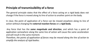
  • 1. The general principle states that the effect of a force acting on a rigid body does not change if the force is moved along its line of action to another point on the body. In clear, the point of application of a force can be moved anywhere along its line of action without changing the external reaction forces on a rigid body. Any force that has the same magnitude and direction, and which has a point of application somewhere along the same line of action will cause the same acceleration and will result in the same moment. Therefore, the points of application of forces may be moved along the line of action to simplify the analysis of rigid bodies. Principle of transmissibility of a force
  • 2. The main thing to be noted is when analyzing the internal forces (stress) in a rigid body, the exact point of application does matter. This difference in stresses may also result in changes in geometry which will may in turn affect reaction forces. For this reason, the principle of transmissibility should only be used when examining external forces on bodies that are assumed to be rigid. Limitation of principle of transmissibility: Principle of transmissibility can be used only for rigid bodies and cannot be used for deformable bodies.
  • 3. The Principle Of Superposition states that when two waves of the same kind meet at a point in space, the resultant displacement at that point is the vector sum of the displacements that the two waves would separately produce at that point. Net effect of forces applied in any sequence on a body is given by the algebraic sum of effect of individual forces on the body
  • 4. Assumptions made in Engineering Mechanics i) All bodies are RIGID. ii) PARTICLE concept can be used wherever applicable. iii) PRINCIPLE OF PHYSICAL INDEPENDENCE of forces is valid. iv) PRINCIPLE OF SUPERPOSITION of forces is valid. v) PRINCIPLE OF TRANSMISSIBILITY of forces is valid.
  • 5. SYSTEM OF FORCES A group or set of forces is called system of forces. Coplanar force system: If all the forces in the system lie in a single plane, it is called coplanar force system. Concurrent force system: If line of action of all the forces in a system passes through a single point it is called concurrent force system. Collinear force system: In a system, all the forces parallel to each other, if line of action of all forces lie along a single line then it is called a collinear force system.
  • 6. Concurrent force system: If the line of action of forces forming the system pass through a common point (point of concurrence) then the system is said to be concurrent. Non-concurrent force system : f the lines of action of forces forming the system do not pass through a common point, then the system is said to be non-concurrent. Parallel force system :It is a particular case of non- concurrent force system in which the line of action of forces forming the system are parallel.
  • 7. COMPOSITION OF FORCES Composition of Forces or compounding is the method to find resultant force of a number of forces acting simultaneously on a body. Methods for finding resultant force(FR) are • Parallelogram Law • Triangle Law • Polygon law • Resolution of forces or Method of Resolution
  • 8. GRAPHICAL METHOD In Graphical method, forces are drawn on graph with some suitable scale and their resultant is measured by Parallelogram law, Triangle Law or Polygon Law. While Parallelogram law is also used as analytical method for resolution of forces. Let’s study the laws used for graphical method for composition of forces. • Parallelogram Law • Triangle Law • Polygon law
  • 9. PARALLELOGRAM LAW OF FORCES “If two consecutive sides of a parallelogram represents the magnitude and direction of two coplaner forces acting on a particle, then its diagonal represents the Resultant Force(FR) in magnitude and direction.” Consider two vectors P⃗ and Q⃗ as shown in the figure. Vector Q⃗ is displaced parallel to itself till the tail end of both the vectors touch at a point O. The parallelogram is completed as shown in the figure. Applying the law of triangle of vectors, to the triangle OAC, we have, OA + AC = OC or P⃗ + Q⃗ = R⃗ → → →
  • 10. Two forces F1 and F2 of magnitudes 80KN and 50KN respectively acting simultaneously on a particle such that the angle between the two forces is 60o. Considering bigger force as F1. Taking some suitable scale and drawing a parallelogram ABCD with Sides AB and AD representing the forces F1 and F2 and having an angle (θ) between them. F1 as AB = 80 mm = 8 cm, F2 as AD = 50 mm = 5 cm θ = 60o According to law of parallelogram diagonal AC is representing the resultant force (FR). Length of the diagonal AC is the magnitude of the resultant force and the angle (α), which diagonal AC is making with the side AB, represents the direction of resultant force (FR). By Measurement Thus the Resultant FR is equal to 113.5 KN acting at an angle (α) 22.5o with F1.
  • 11. TRIANGLE LAW OF FORCES “If two sides of a triangle, taken in order, represents the magnitude and direction of two coplaner forces acting on a partical, then its third side, taken in opposite order represents the Resultant Force(FR) in magnitude and direction.” Taking some suitable scale (1KN = 1 mm) drawing a triangle ABC with sides AB and BC representing the forces F1 and F2 and having an angle (θ) between BC and extended side AB F1 as AB = 80 mm = 8 cm, F2 as BC = 50 mm = 5 cm θ = 60o According to triangle law of forces side AC is representing the resultant force (FR). Length of side AC is the magnitude of the resultant force and the angle (α), which side AC is making with side AB represents the direction of resultant force (FR). By Measurement
  • 12. Triangle and parallelogram law are best suited for system of forces having two forces acting simultaneously on a body. For a system of forces having more than two forces, Polygon law of forces is applied. Thus the Resultant FR is equal to 113.5 KN acting at an angle (α) 22.5o with F1.
  • 13. POLYGON LAW OF FORCE “If sides of a polygon, taken in order, represents the magnitude and direction of more than two coplaner forces, acting on a partical, then its closing side, taken in opposite order, represents the Resultant Force(FR) in magnitude and direction.”
  • 14. Let us consider a system of forces F1, F2, F3 & F4. Having magnitude as 25 KN, 35 KN, 30 KN & 20 KN, making an angle of 30o, 45o, 40o and 80o with horizontal Taking some suitable scale (1KN = 1 mm) drawing the sides of polygon ABCDE with Sides AB, BC, CD & DE representing the forces F1, F2, F3 & F4, having respective angle between them. Joining point A and E to draw the closing side AE.
  • 15. Joining point A and E to draw the closing side AE. F1 as AB = 25 mm = 2.5 cm, F2 as BC = 35 mm = 3.5 cm F3 as CD = 30 mm = 3 cm, F4 as DE = 20 mm = 2 cm Angle between F1 and F2 is 105o Angle between F2 and F3 is 95o A B C D E
  • 16. F1 as AB = 25 mm = 2.5 cm, F2 as BC = 35 mm = 3.5 cm F3 as CD = 30 mm = 3 cm, F4 as DE = 20 mm = 2 cm A B B C C D D E
  • 18.
  • 19.
  • 20. According to polygon law of forces, side AE is representing the resultant force (FR). Length of side AE is the magnitude of the resultant force and the angle (α) which side AE is making with side AB represents the direction of resultant force (FR). Thus the Resultant FR is equal to 22.6 KN acting at an angle (α) 154.4o with F1.
  • 21. ANALYTICAL METHOD Analytical method is different from graphical method. Let us study analytical method for finding the resultant force for number of forces acting simultaneously on a particle. There are two analytical methods for composition of forces, Parallelogram law and Method of Resolution. PARALLELOGRAM LAW OF FORCES
  • 22. “If two consecutive sides of a parallelogram represents the magnitude and direction of two coplaner forces acting on a partical, Then the Resultant Force (FR) and angle α is obtained by
  • 23. Solving Illustration 1 by parallelogram law Resultant Force FR will be The angle (α) which resultant FR is making with force F1
  • 24. RESOLUTION OF FORCES FOR RESULTANT FORCE Before understanding the method of finding resultant force by method of Resolution let us understand what resolution of forces is. Resolution of Forces Resolution of forces is the process of breaking a force into two components, basically horizontal and vertical components. Suppose force (F) acting on a particle such that, it is making an angle (θ) with horizontal axis (AB).
  • 25. Horizontal Component It is the product of magnitude of force and the cosine of the angle, it is making with horizontal axis. Direction of the component is considered same as the direction of horizontal axis, with which it is making the angle θ. Vertical Component It is the product of magnitude of force and the sine of the angle, it is making with horizontal axis. Direction of the component is considered same as the direction of vertical axis, normal to the horizontal axis with which it is making the angle θ.
  • 26. PRINCIPLE OF FINDING RESULTANT FORCE BY THE METHOD OF RESOLUTION OF FORCES “The resolved parts of the forces in a particular direction will be equal to the resolved parts of resultant force in same direction.” Method of resolution of forces starts with summation of Horizontal Components in a system of forces is represented By ∑H while summation of Vertical Components is represented by ∑V. ∑H = Sum of Horizontal Components in a system of forces. = F1cos θ1 + F2cos θ2 + F3cos θ3 +_ _ _+ Fn cos θn ∑V = Sum of Vertical Components in a system of forces. = F1sin θ1 + F2sin θ2 + F3sin θ3 +_ _ _+ Fn sin θn
  • 27. Direction of resultant in terms of angle(α) is obtained by Magnitude of resultant force is obtained by
  • 28. Solving Illustration 2 with method of resolution Evaluating ∑H and ∑V (Using sign convention) ∑H = 25 cos 30o + 20 cos 80o + (-30 cos 40o) + (-35 cos 45o) = 25 cos 30o + 20 cos 80o – 30 cos 40o – 35 cos 45o = – 22.60 ∑H = – 22.60 (-ve) Similarly ∑V = 25 sin 30o + 35 sin 45o + (- 30 sin 40o) + (- 20 sin 80o) = 25 sin 30o + 35 sin 45o – 30 sin 40o – 20 sin 80o = – 1.73 ∑V = – 1.73 (-ve) Resultant Force FR
  • 29. Resultant Force FR The angle (α), which resultant (FR) making with horizontal axis.
  • 30. In Solution of illustration 2 by polygon law, α is the angle which resultant FR is making with force F1. Here α is the angle, which resultant FR is making with horizontal axis in negative direction. Thus angle between FR and F1 will be Thus sum of both horizontal and vertical Component of forces is negative, the resultant will lie in 3rd quadrant.
  • 31. Two forces 5 N and 20 N are acting at an angle of 120 degree between them . Find the resultant force in magnitude and direction. When vectors act as maximum and minimum? Solution : It is to be noted that the magnitude of the resultant of two vectors is maximum , when the vectors act in the same direction and is minimum when they act in opposite directions. Two forces 10 N and 14 N are acting upon the a body . What can be the maximum and minimum resultant force on the body ?
  • 32. Two forces 5 N and 20 N are acting at an angle of 120 degree between them . Find the resultant force in magnitude and direction. When vectors act as maximum and minimum? Solution : It is to be noted that the magnitude of the resultant of two vectors is maximum , when the vectors act in the same direction and is minimum when they act in opposite directions. Two forces 10 N and 14 N are acting upon the a body . What can be the maximum and minimum resultant force on the body ?
  • 33. Two forces 5 N and 20 N are acting at an angle of 120 degree between them . Find the resultant force in magnitude and direction. Two forces 10 N and 14 N are acting upon the a body . What can be the maximum and minimum resultant force on the body ?
  • 34. Two forces 5 N and 20 N are acting at an angle of 120 degree between them . Find the resultant force in magnitude and direction. Two forces 10 N and 14 N are acting upon the a body . What can be the maximum and minimum resultant force on the body ?
  • 35. Drawing Free-Body Diagrams Free-body diagrams are diagrams used to show the relative magnitude and direction of all forces acting upon an object in a given situation. 1. The size of the arrow in a free-body diagram reflects the magnitude of the force. 2. The direction of the arrow shows the direction that the force is acting. 3. Each force arrow in the diagram is labelled to indicate the exact type of force. It is generally customary in a free-body diagram to represent the object by a box and to draw the force arrow from the centre of the box outward in the direction that the force is acting
  • 36.
  • 37. Force Symbol Magnitude Direction Gravity (weight) F(G) = mobject*g (9.8 m/s2) Downward Normal (surface) F(N) any (up to breaking load) perpendicular to surface Tension F(T) any (up to breaking load) along string/rope/chain Friction F(fr) not slipping: between zero and ms*F(N) slipping: = mk*F(N) Direction opposing relative motion.
  • 38. Horizontal Component It is the product of magnitude of force and the cosine of the angle, it is making with horizontal axis. Direction of the component is considered same as the direction of horizontal axis, with which it is making the angle θ. Vertical Component It is the product of magnitude of force and the sine of the angle, it is making with horizontal axis. Direction of the component is considered same as the direction of vertical axis, normal to the horizontal axis with which it is making the angle θ.
  • 39. •A book is at rest on a tabletop. Diagram the forces acting on the book. •A girl is suspended motionless from the ceiling by two ropes. Diagram the forces acting on the combination of girl and bar..
  • 40. A book on a table In this example, there are two forces acting on a book at rest on a table: 1) The weight W exerted by the earth on the book 2) The normal force N exerted by the table on the book. A suspended block In this example, there are two forces acting on the suspended block at rest: 1) The weight W exerted by the earth on the block 2) The tension force T exerted by the string (or rope) on the block.
  • 41. A block on a floor with an acting force Fa to pull the block In this example, the block is being pulled and therefore a force of friction acts on the block. So there are four forces acting on the block. 1) The weight W exerted by the earth on the block 2) The normal force N exerted by floor on the block. 3) The acting force Fa to pull the block. 4) The force of friction Ff exerted by floor on the block in the direction opposite the motion due to Fa.
  • 42. A falling object In this example, there is only one force action on the falling object. 1) The weight W exerted by the earth on the falling object. A falling object with Air Friction here only two force action on the falling object. 1) The weight W exerted by the earth on the falling object. 2) The Friction FAir
  • 43. An box on an incline plane (with no frictions) In this example, we assume that the inclined plane is frictionless; two forces act on the box: 1) The weight W exerted by the earth on the box. 2) The normal force N exerted by the inclined plane on the box. N is normal to the inclined plane.
  • 44. An box on an incline plane with an acting force and friction considered. In this example, a force Fa pulls the box upward and frictions are not negligible. Four forces act on the box: 1) The weight W exerted by the earth on the box. 2) The normal force N exerted by the inclined plane on the box. N is normal to the inclined plane. 3) The acting force Fa. 4) The force of friction Fs exerted by the inclined plane on the box in the direction opposite the motion due to Fa.
  • 45.
  • 46.
  • 47.
  • 48.
  • 49.
  • 50. A block suspended to the ceiling using three strings. A) free body diagram for the block; two forces (lower part of figure below) 1) The weight W exerted by the earth on the box. 2) The tension force T '3 exerted by the string on the block. B) free body diagram of point P; three forces (upper part of figure below) 1) Tension T1 2) Tension T2 3) Tension T3
  • 51.
  • 52.
  • 53.
  • 54. A system with two blocks, an inclined plane and a pulley. A) free body diagram for block m1 (left of figure below) 1) The weight W1 exerted by the earth on the box. 2) The normal force N 3) The force of friction Fk 4) The tension force T exerted by the string on the block m1. B) free body diagram of block m2 (right of figure below) 1) The weight of the block W2 2) Tension T '.
  • 55. Determining the Net Force In the statement of Newton's first law, the unbalanced force refers to that force that does not become completely balanced (or canceled) by the other individual forces. If either all the vertical forces (up and down) do not cancel each other and/or all horizontal forces do not cancel each other, then an unbalanced force exists. The existence of an unbalanced force for a given situation can be quickly realized by looking at the free-body diagram for that situation. Free-body diagrams for three situations are shown below. Note that the actual magnitudes of the individual forces are indicated on the diagram.
  • 56.
  • 57.
  • 58.
  • 59.
  • 60. Free-body diagrams for four situations are shown below. The net force is known for each situation. However, the magnitudes of a few of the individual forces are not known. Analyze each situation individually and determine the magnitude of the unknown forces.
  • 61. The force F is producing, simultaneous x displacement and y-displacement. The part of the force F which is producing x displacement is called x component or horizontal component of the force F(Fx). The part of the force F which produces y – displacement is called y component of the force or vertical component of force F(Fy). The technique of finding a component of a force along any direction is called resolution of force. The component of a force along any direction is called the resolved component. The components of a force determined along two mutually perpendicular direction are called rectangular components. RESOLUTION OF A FORCE
  • 62. In the diagram the force F is resolved into two perpendicular component forces that is the Fy and Fx components (using parallelogram method). To calculate the magnitude of the vertical (Fy) and horizontal (Fx) forces, we can use simple trigonometry. Fx = F cos θ , Since cos θ = (Fx/F) Fy = F sin θ, Since sin θ = (Fy/ F)
  • 63. Horizontal Component It is the product of magnitude of force and the cosine of the angle, it is making with horizontal axis. Direction of the component is considered same as the direction of horizontal axis, with which it is making the angle θ. Vertical Component It is the product of magnitude of force and the sine of the angle, it is making with horizontal axis. Direction of the component is considered same as the direction of vertical axis, normal to the horizontal axis with which it is making the angle θ.
  • 64. To calculate the magnitude of the vertical (Fy) and horizontal (Fx) forces, we can use simple trigonometry. Fx = F cos θ , Since cos θ = (Fx/F) Fy = F sin θ, Since sin θ = (Fy/ F)
  • 65.
  • 66. Note: 1. Sign convention for the direction of components. The horizontal component or ‘X’ component of a force acting along x direction is the force itself. Whereas, its vertical component or y-component is zero. 2.
  • 67. ‘x’ component of a force acting along Y direction is zero. Whereas, its ‘y’ component is equal to itself. 4. If a force is inclined at 45o w.r.t. x axis or y axis then its x component will be equal to y component (Fx= Fy).

Notes de l'éditeur

  1. The law of parallelogram of forces states that if two vectors acting on a particle at the same time be represented in magnitude and direction by the two adjacent sides of a parallelogram drawn from a point their resultant vector is represented in magnitude and direction by the diagonal of the parallelogram drawn from the same point .
  2. Fx = + 20 Cos 70 = + 6 . 840 kN = 6 . 840 kN () Fy = + 20 Sin 70 = + 18 . 79 kN = 18 . 79 kN ()
  3. Here A = 5 N B = 20 N ; θ= 120 degree ; R= ?; beta =? R= sqrt of A^2+ B^2+ 2 AB cosθ = sqrt of 5^2 + 20^2+ 2 X 5 X 20 cos 120 degree = sqrt of 325 = 18.03 N tan beta = 5 sin 120 /20 + 5 cos 120 = 5 sqrt 3 / 2 /20 +5 X (-0.5) = 0.2475 = tan 13 degree 54 min hence, beta = 13 degree 54′
  4. Here A = 5 N B = 20 N ; θ= 120 degree ; R= ?; beta =? R= sqrt of A^2+ B^2+ 2 AB cosθ = sqrt of 5^2 + 20^2+ 2 X 5 X 20 cos 120 degree = sqrt of 325 = 18.03 N tan beta = 5 sin 120 /20 + 5 cos 120 = 5 sqrt 3 / 2 /20 +5 X (-0.5) = 0.2475 = tan 13 degree 54 min hence, beta = 13 degree 54′
  5. Here A = 5 N B = 20 N ; θ= 120 degree ; R= ?; beta =? R= sqrt of A^2+ B^2+ 2 AB cosθ = sqrt of 5^2 + 20^2+ 2 X 5 X 20 cos 120 degree = sqrt of 325 = 18.03 N tan beta = 5 sin 120 /20 + 5 cos 120 = 5 sqrt 3 / 2 /20 +5 X (-0.5) = 0.2475 = tan 13 degree 54 min hence, beta = 13 degree 54′
  6. Here A = 5 N B = 20 N ; θ= 120 degree ; R= ?; beta =? R= sqrt of A^2+ B^2+ 2 AB cosθ = sqrt of 5^2 + 20^2+ 2 X 5 X 20 cos 120 degree = sqrt of 325 = 18.03 N tan beta = 5 sin 120 /20 + 5 cos 120 = 5 sqrt 3 / 2 /20 +5 X (-0.5) = 0.2475 = tan 13 degree 54 min hence, beta = 13 degree 54′
  7. The net force is zero Newtons. All the individual forces balance each other (i.e., cancel each other out). The net force is 5 Newtons, left. The vertical forces balance each other (i.e., cancel each other out). The leftward force (friction) remains unbalanced. The net force is zero Newtons. All the individual forces balance each other (i.e., cancel each other out). The net force is 15 Newtons, up. The upward force of air resistance is only partially balanced by the downward force of gravity - 15 N of upward force remains unbalanced.
  8. A = 50 N (the horizontal forces must be balanced) B = 200 N (the vertical forces must be balanced) C = 1100 N (in order to have a net force of 200 N, up) D = 20 N (in order to have a net force of 60 N, left) E = 300 N (the vertical forces must be balanced) F = H = any number you wish (as long as F equals H) G = 50 N (in order to have a net force of 30 N, right)
  9. X component of a force is given by the product of magnitude of the force and cosine of acute angle made by the force w.r.t. x-direction. Y component of a force is given by the product of magnitude of the force and sine of acute angle made by the force w.r.t. x-direction.
  10. Here A = 5 N B = 20 N ; θ= 120 degree ; R= ?; beta =? R= sqrt of A^2+ B^2+ 2 AB cosθ = sqrt of 5^2 + 20^2+ 2 X 5 X 20 cos 120 degree = sqrt of 325 = 18.03 N tan beta = 5 sin 120 /20 + 5 cos 120 = 5 sqrt 3 / 2 /20 +5 X (-0.5) = 0.2475 = tan 13 degree 54 min hence, beta = 13 degree 54′