➥🔝 7737669865 🔝▻ kakinada Call-girls in Women Seeking Men 🔝kakinada🔝 Escor...
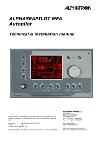
ALPHASEAPILOT MFA Autopilot
1. ALPHASEAPILOT MFA
Autopilot
Technical & installation manual
ALPHATRON MARINE B.V.
Schaardijk 23
3063 NH ROTTERDAM
The Netherlands
Tel: +31 (0)10 – 453 4000
Fax: +31 (0)10 – 452 9214
P.O. Box 210003
3001 AA ROTTERDAM
Web: www.alphatronmarine.com
Mail: service@alphatronmarine.com
The information in this Manual is subject to change without notice and
does not represent a commitment on the part of ALPHATRON MARINE
B.V.
Document : Manual ALPHASEAPILOT MFA
Issue : 1.2
ALPHATRON MARINE B.V.
Manufactured for Alphatron by Navitron Systems Ltd., Havant Hants UK
2. Technical manual ALPHASEAPILOT MFA Issue 1.2 Page 2 of 191
ALPHASEAPILOT MFA
- Contents -
Section 1: Std. Unit Dimensions and Installation.................................................. 12
1.1 The ALPHASEAPILOT MFA Control Unit Installation (FIG 1.1) ................... 12
1.2 The ALPHASEAPILOT MFA Distribution Unit Installation ............................. 14
1.3 The Heading Sensor Coil type HSC2 ............................................................... 15
1.4 Heading Sensor Coil type HSC1 Installation (FIG. 1.4) .............................. 16
1.5 Compass Junction Box Installation (FIG 1.5)................................................ 18
1.6 Rudder Reference Unit Installation (FIG 1.6)................................................ 19
Section 2: Standard Unit Cables & Connections ......................................................... 22
2.0 Cable Routing and Earth Bonding.................................................................... 22
2.0.1 Auto / Manual Steering Mode Changeover ................................ 24
2.1 ALPHASEAPILOT MFA Distribution Unit Services and Connections ........... 26
2.2 HSC2 Heading Sensor Coil Connections to Compass Junction Box........... 28
2.3 NMEA Heading Input Connections ................................................................... 29
2.4 NMEA No.1 Speed Input Data Connections ................................................... 31
2.5 NMEA No. 2 & Pulse Type Speed Data Input Connections.......................... 32
2.6 4-20mA Draft Input Connections..................................................................... 33
2.7 NMEA Track Data Input Connections .............................................................. 33
2.8 Isolated Remote Steer Input Connections..................................................... 34
2.9 Rudder Reference Unit Connections................................................................ 34
2.10 Solenoid Connections ..................................................................................... 36
2.11 Channel A +/-10Vdc Analogue Output Connections ................................ 38
2.12 Channel A 4-20mA Output Connections ..................................................... 38
2.13 Channel B +/-10Vdc Analogue Output Connections ................................ 39
2.14 Channel B 4-20mA Output Connections ..................................................... 39
2.15 Analogue Thruster ±10Vdc Output Connections....................................... 39
2.16 Analogue Thruster 4-20mA Output Connections ...................................... 40
2.17 Chan 1 Isolated NMEA 0183 Heading/Track Data Outputs..................... 40
2.18 Chan 2 Isolated NMEA 0183 Status Data Outputs ................................... 41
2.19 Optional Step By Step Output Connections ............................................... 41
2.20 Optional Furuno Data Output Connections................................................. 42
2.21 Optional Status Contacts ............................................................................... 42
2.22 Optional System Fail Contacts...................................................................... 42
2.23 Optional (Auxiliary) Off Heading Alarm Contacts...................................... 42
2.24 Optional (Auxiliary) Watch Alarm Contacts................................................ 43
2.25 Optional Power (Fail) Monitor Contacts ...................................................... 43
2.26 Optional Remote Power Up/Engage Connections...................................... 43
2.27 Non Isolated Remote Power Steer Inputs...................................................... 43
2.28 Rudder System Enable Inputs ...................................................................... 44
3. Technical manual ALPHASEAPILOT MFA Issue 1.2 Page 3 of 191
ALPHASEAPILOT MFA
Section 3: Installation Adjustments and Alongside Trials ................................... 46
3.0 Essential ALPHASEAPILOT MFA Control Unit Address Reprogramming.... 46
3.1 Limit Switch Adjustment ................................................................................... 47
3.2 Autopilot and Solenoid Power Supply ............................................................. 48
3.3 Feedback Phase Connections............................................................................ 49
3.4 Set Up Menu ........................................................................................................ 50
3.5 DISPLAY Contrast Adjust................................................................................... 52
3.6 Display Invert ...................................................................................................... 52
3.7 REMOTE BRIGHT (Remote NMEA Dimmer Data Input)............................... 52
3.8 LOOP GAIN........................................................................................................... 53
3.9 VESSEL TYPE (Displacement or High Speed Craft Autopilot Operation).. 53
3.10 ROT SCALING (Deg/Sec or Deg/Min).......................................................... 53
3.11 RATE OF TURN (ROT) MAXIMUM.................................................................. 54
3.12 RATE OF TURN (ROT) OPERATIONAL CALIBRATION................................ 54
3.13 Autotrim Secs (APH Time Constant)............................................................ 54
3.14 Autotrim Trip (Automatic APH Cancellation vs Course Change)............ 54
3.15 Autotrim Mode ................................................................................................. 55
3.16 Thruster ENABLE (Bowthruster Output On/Off)........................................ 55
3.17 RUDDER REFERENCE UNIT A (RRU A) TYPE SELECTION ........................ 55
3.18 RRU A ROTATE (Sin/Cos Rudder Ref Unit Signal Calibration)................ 56
3.19 RRU A Midships Calibration ........................................................................... 56
3.20 RRU A RAI Cal (rudder Angle Calibration).................................................. 56
3.21 Rudder Bar Cal................................................................................................. 56
3.22 RUDDER REFERENCE UNIT B (RRU B) TYPE SELECTION....................... 57
3.23 RRU B ROTATE (Sin/Cos Rudder Ref Unit Signal Calibration)................ 57
3.24 RRU B Midships Calibration ........................................................................... 57
3.25 RRU B RAI Cal (rudder Angle Calibration).................................................. 58
3.26 SOLENOIDS (Enable/Disable)....................................................................... 58
3.27 Elect Limit Swit (Electronic Limit Switches)............................................... 58
3.28 Port Limit Swit A (PORT Limit Switch Adjustment) .................................. 58
3.29 STBD Limit Swit A (STBD Limit Switch Adjustment)................................ 58
3.30 Port Limit Swit B (PORT Limit Switch Adjustment) .................................. 59
3.31 STBD Limit Swit B (STBD Limit Switch Adjustment)................................ 59
3.32 Rudd. Posn. Sens A (Rudder Position Sensitivity) .................................... 59
3.33 Auto Stability A................................................................................................ 59
3.34 Rudd. Posn. Sens B (Rudder Position Sensitivity) .................................... 60
3.35 Auto Stability B................................................................................................ 60
3.36 Lost Motion (ON/OFF)..................................................................................... 60
3.37 Lost Motion Calibration A (Rudder Demand Hold On Time).................... 61
3.37 Lost Motion Calibration B (Rudder Demand Hold On Time).................... 61
3.39 CHANNEL A Analogue Output (Position vs Error) ..................................... 62
3.40 CHANNEL A Analogue Voltage Offset (Midships Alignment Cal) ............ 63
3.41 CHANNEL A Voltage Gain (Demanded Position vs mV/degree) ............. 63
3.42 CHANNEL A Current Offset (Midships Cal) ................................................. 64
3.43 CHANNEL A Current Gain (Demanded Position vs mA/deg)................... 65
3.44 CHANNEL B Analogue Output (Position vs Error) ..................................... 65
3.45 CHANNEL B Analogue Voltage Offset (Midships/Zero Thrust Cal)......... 66
3.46 CHAN B Voltage Gain (Demanded Position/Thrust % vs mV/degree).. 66
4. Technical manual ALPHASEAPILOT MFA Issue 1.2 Page 4 of 191
ALPHASEAPILOT MFA
3.47 CHANNEL B CURRENT OFFSET (Midships/Zero Thrust Cal).................... 67
3.48 CHANNEL B Current Gain (Dem. Position/% Thrust vs mA Output)..... 68
3.49 Thruster 1 Voltage Offset (Zero Thrust Cal.)............................................. 68
3.50 Thruster 1 Voltage Gain................................................................................. 69
3.51 Thruster1 Current Offset................................................................................ 70
3.52 Thruster 1 Current Gain................................................................................. 70
3.53 Analogue Steering Fail Alarm (On/Off) ....................................................... 71
3.54 Analogue Steering Alarm Limit..................................................................... 71
3.55 Analogue Steering NFU Time ........................................................................ 72
3.56 FU Calibration in Thruster Mode (FU IN THRUST CAL) ............................ 72
3.57 Remote Steer Alarm ....................................................................................... 72
3.58 Sensor Coil Type (Selection)......................................................................... 72
3.59 Coil Heading ..................................................................................................... 73
3.60 Coil Signal......................................................................................................... 73
3.61 Mag Priority (Coil vs NMEA) .......................................................................... 73
3.62 Auto/Manual Deviation Correction ............................................................... 73
3.63 NMEA Chanel Priority (Ch 1 vs Ch 2 vs Ch 3) ........................................... 74
3.64 NMEA Data Type.............................................................................................. 74
3.65 NMEA1 In+Out BD (NMEA Chan 1 Input/Output Baud Rate)................. 74
3.66 NMEA 1 O/P RatE (NMEA Chan 1 Output Update Rate)........................... 75
3.67 NMEA 2 I/P Baud (NMEA Chan 2 Input Baud Rate). ................................ 75
3.68 NMEA 3 I/P Baud (NMEA Chan 3 Input Baud Rate).................................. 75
3.69 Track Baud Rate .............................................................................................. 75
3.70 CH1 Speed Input Data (NMEA Baud Rate)................................................. 75
3.71 NMEA Output Data (CH2) & SOG Speed Input Data................................ 75
3.72 O.H.A. Delay (Off Heading Alarm) ............................................................... 76
3.73 Off Heading Alarm (OHA) Time Out............................................................. 76
3.74 Course Comparator Alarm............................................................................. 76
3.75 Set course Alarm (Course Change Alarm) ................................................. 76
3.76 New (SET) Course Alarm Time Out ............................................................. 76
3.77 Furuno O/P Res (Furuno Output Data Resolution) ................................... 77
3.78 Furuno O/P Rate (Furuno Output Data Update Rate) .............................. 77
3.79 Isolated FU Steering A Select (Norm, HSC Latch, Jog) ........................... 77
3.80 Isolated FU Steering A Midships Cal............................................................ 77
3.81 Isolated FU Steering A Gain Cal ................................................................... 78
3.82 Isolated FU Steering B Select (Norm, HSC Latch, Jog) ........................... 78
3.83 Isolated FU Steering B Midships Cal............................................................ 78
3.84 Isolated FU Steering B Gain Cal ................................................................... 78
3.85 Step By Step Input Ratio............................................................................... 79
3.86 Step By Step Heading Output (3, 6, 12, 24 Steps/Deg)......................... 79
3.87 Step By Step Output Rate (8, 16, 24 Deg/Sec max.).............................. 79
3.88 Control Unit Address Selection (Null, 1, 2 or 3)........................................ 79
3.89 Expansion Box (Enable/Disable) .................................................................. 79
3.90 Rest To Factory Default Settings.................................................................. 80
3.91 Save Set Up (User) Data ............................................................................... 80
3.92 Load (Recall) Installation Set Up (User) Data ........................................... 80
3.93 To Exit The Set Up Mode ............................................................................... 80
5. Technical manual ALPHASEAPILOT MFA Issue 1.2 Page 5 of 191
ALPHASEAPILOT MFA
Section 4: Optional Equipment Installation............................................................ 81
4.1 Watch Alarm Type NT920WA............................................................................ 81
4.2 NT920NFU (Navitron Non Follow Up Power Steer & Dodge Control)........ 84
4.3 NT990FU (Navitron Power Steer Control)...................................................... 87
4.4 NT920HRC (Navitron Hand Held Follow Up Power Steer)........................... 90
4.5 Navitron Rudder Angle Indicator Type NT920RAI ........................................ 93
4.6 Digital Heading Repeater Type NT920DHR MKII.......................................... 97
4.7 Analogue Heading Repeater Type NT920AHR MK2.................................... 101
4.8 Universal Relay Box Type NT920URB ........................................................... 105
4.9 Step Interface Box Type NT925SIB .............................................................. 109
Section TM1: Basic System Component Data........................................................ 111
TM1.1 Heading Sensor Coil (HSC2)........................................................................ 112
TM1.2 ALPHASEAPILOT MFA Distribution Unit...................................................... 112
TM1.3: NMEA 0183 Heading Data............................................................................ 114
TM1.4: Rudder Reference Unit (NT920RRU).......................................................... 119
TM1.5: The Autopilot Control Unit............................................................................ 122
TM1.5.1: The Control Unit Front Panel Sub Assembly .............................122
TM1.6: The Track Function........................................................................................ 124
TM1.6.1: Use of APB Sentence ............................................................124
TM1.6.2: Use of HSC Sentence............................................................125
TM1.6.3: Use of HTC Sentence............................................................125
Section TM2: Failure Alarms and Messages........................................................... 128
TM2.1: Power Up Failure Messages ......................................................................... 128
TM2.1.1: SET DAT FAIL (Non Volatile Set Up Data Failure to Load) ..........128
TM2.1.2: DATA ERROR (Corrupted DB Data).........................................129
TM2.1.3: COMM FAIL (CU to DB data communication failure)..................130
TM2.2: Heading Sensor Failure Messages .............................................................. 130
TM2.2.1: CPS HI FAIL (Signal from HSC is too large) .............................130
TM2.2.2: CPS LO FAIL (Signal Amplitude from HSC too low) ...................130
TM2.2.3: CPS PHS FAIL (Signals from the 3 sense lines not consistent)....131
TM2.2.4: COMPASS FAIL (High ROT/Rate of change) .............................131
TM2.2.5: HDT 1 FAIL (Channel 1 input)................................................131
TM2.2.6: HDG 1 FAIL (Channel 1 input) ...............................................132
TM2.2.7: HDM 1 FAIL (Channel 1 input) ...............................................132
TM2.2.8: HCC 1 FAIL (Channel 1 input)................................................132
TM2.2.9: HDT 2 FAIL (Channel 2 Input) ...............................................132
TM2.2.10: HDG 2 FAIL (Channel 2 Input) .............................................132
TM2.2.11: HDM 2 FAIL (Channel 2 Input) .............................................132
TM2.2.12: HCC 2 FAIL (Channel 2 Input)..............................................132
TM2.2.13: HDT 3 FAIL (Channel 3 Input)..............................................132
TM2.2.14: HDG 3 FAIL (Channel 3 Input) .............................................132
TM2.2.15: HDM 3 FAIL (Channel 3 Input) .............................................133
TM2.2.16: HCC 3 FAIL (Channel 3 Input)..............................................133
TM2.2.17: NO NMEA H`DG IN (No Heading Data)..................................133
TM2.2.18: CCA DAT FAIL (CCA NMEA Data Fail) ....................................133
6. Technical manual ALPHASEAPILOT MFA Issue 1.2 Page 6 of 191
ALPHASEAPILOT MFA
TM2.2.19: STEP FAIL .........................................................................133
TM2.2.20: STEP ALIGN.......................................................................133
TM2.3: Miscellaneous Failure Messages.................................................................. 134
TM2.3.1: MAIN PWR FAIL (Main Power)................................................134
TM2.3.2: BACK PWR FAIL (Back Up Power)...........................................134
TM2.3.3: D. BOX FAIL (Distribution Unit)..............................................134
TM2.3.4: REMOTE FAIL (Control Unit Communication) ...........................134
TM2.3.5: NO DATA (No User Data Stored) ............................................134
TM2.3.6: RRU FAIL (Rudder Reference Unit Failure)...............................135
TM2.3.7: L/SW OPEN (Limit Switch Status)...........................................135
TM2.3.8: STEER`G FAIL (Steering System Fail).....................................136
TM2.3.9: MASTER REM. OFF/REMOTE 1 (2) (3) REQUEST.......................136
TM2.3.10: +7V FAIL .........................................................................137
TM2.3.11: +3.5V FAIL........................................................................137
TM2.3.12: +2.5V FAIL........................................................................137
TM2.3.13: NO ORIDE CAL (No override cal – HSC requirement) ..............137
TM2.4: Speed / Draft Data Alarms .......................................................................... 137
TM2.4.1: NO SOG DATA (NMEA speed over the Ground) ........................137
TM2.4.2: NO STW DATA (NMEA or pulse log Speed through the Water)....137
TM2.4.3: SPEED LOW (SOG inadequate) ..............................................138
TM2.4.4: Draft In Fail ........................................................................138
TM2.5: Track Mode Data, Warnings & Alarms....................................................... 138
TM2.5.1: HTS DATA...........................................................................138
TM2.6: Operational Alarms........................................................................................ 139
TM2.6.1: >x° OFF HEADING (Off heading alarm trip level) .....................139
TM2.6.2: CCA LIMIT (Course comparator) ............................................139
TM2.6.3: WATCH xx MIN (3 to 12 min periods) .....................................139
TM2.6.4: RUDDER LIMIT ....................................................................139
TM2.6.5: REM STR ON (Remote Steer On)............................................139
TM2.7: Ethernet Alarms ............................................................................................. 139
TM2.7.1: ETHERNET A FAIL ................................................................139
TM2.7.2: ETHERNET B FAIL ................................................................139
TM2.8: Operational Display Messages..................................................................... 140
TM2.9: Operational Status LED’s.............................................................................. 141
Section TM3: Application Notes.................................................................................... 142
TM3.1: Port & Stbd Solenoid Switching Stages..................................................... 142
TM3.2: The Rudder Reference (Feedback) Potentiometer .................................. 142
TM3.3: Analogue Outputs to Steering Machines & Thrusters............................. 147
TM3.3.1: Feedback (Rudder Reference Unit) Signals ..............................147
TM3.3.2: Demanded Position versus Proportional Error Systems..............148
TM3.3.3: Feedback Application Note ....................................................149
TM3.3.4: Feedback Options ................................................................149
TM3.3.5: Feedback Connections ..........................................................152
TM3.3.6: Steering System Configurations.............................................153
TM3.4: Proprietary Remote Power Steer Connections ......................................... 157
TM3.4.1: Full Follow Up and Non Follow Up Operating Conditions ............157
7. Technical manual ALPHASEAPILOT MFA Issue 1.2 Page 7 of 191
ALPHASEAPILOT MFA
TM3.4.2: Non Follow Up Mode.............................................................157
TM3.4.3: Full Follow Up Mode .............................................................158
TM3.4.4: Dodge Operation..................................................................158
TM3.5: Proprietary Follow Up Wheel And Override Power Steer ....................... 160
TM3.5.1: Proprietary FU Power Steer Using Dist. Unit 10Vdc Supply ........160
TM3.5.2: Follow Up External Supply to 10Vdc max ................................161
TM3.5.3: Follow Up External Supply to ±10Vdc (20V max) .....................161
TM3.5.4: Latched & Non Latched Override Connections ..........................162
TM3.6: Auxiliary Status Alarm Relay Contacts ...................................................... 162
TM3.6.1: Optional Status Contacts.......................................................162
TM3.6.2: Optional System Fail Contacts ...............................................162
TM3.6.3: Optional (Auxiliary) Off Heading Alarm Contacts ......................163
TM3.6.4: Optional (Auxiliary) Watch Alarm Contacts ..............................163
TM3.6.5: Optional Power (Fail) Monitor Contacts ...................................163
TM3.6.6: Analogue OUTPUT CHANNELS A & B & Thruster .......................163
Section TM4: ALPHASEAPILOT MFA Distribution Unit Power Distribution............ 164
TM4.1: Main and Secondary Power Supplies ......................................................... 164
TM4.2: Connector PCB +12V, +7V & +3.5V Regulation...................................... 164
TM4.3: Non Isolated +5V Processor(s) Supply ..................................................... 164
TM4.4: Isolated +5Vdc Supplies for NMEA and Furuno Output Data................ 165
TM4.5: Isolated ±5Vdc Supplies for Isolated Steering Inputs ............................ 166
TM4.6: Isolated +5Vdc Supply for 4-20mA Draft Input ...................................... 166
TM4.7: Isolated Suppl. for ±13Vdc & 4-20mA Analogue Steering & Thruster. 167
TM4.8: Isolated +5V Supplies for Rudder Reference Units (RRUs)................... 167
TM4.9: Ethernet 3.3V Supply (Drwg NTD920760/4 & 5 of 5)............................ 168
TM4.10: ALPHASEAPILOT MFA Connector PCB Schematic NTD920759 ........... 169
TM4.11: ALPHASEAPILOT MFA Main PCB Schematic NTD920760 ..................... 174
Section TM5: The ALPHASEAPILOT MFA Diagnostic Mode...................................... 177
TM5.1: To Enter Diagnostic Mode:- ......................................................................... 177
TM5.2: To Exit the Diagnostic Mode ........................................................................ 179
Section TM6: ALPHASEAPILOT MFA DB Main Connector Layouts/Schematics.... 180
Section TM7: ALPHASEAPILOT MFA CU PCB Layout/Schematics .......................... 180
TM6 (v): ALPHASEAPILOT Connector PCB Schematic NTD920759 Page 3...... 181
TM6 (v): ALPHASEAPILOT Connector PCB Schematic NTD920759 Page 5...... 182
TM6 (v): ALPHASEAPILOT Connector PCB Schematic NTD920759 Page 7...... 183
TM6 (iii): ALPHASEAPILOT Main PCB Schematic NTD920760 Page 2............... 184
TM6 (iii): ALPHASEAPILOT Main PCB Schematic NTD920760 Page 3............... 185
TM7 (ii): ALPHASEAPILOT Control Unit PCB Layout Top .................................... 186
TM7 (ii): ALPHASEAPILOT Control Unit PCB Layout Bottom.............................. 187
TM7 (iii): ALPHASEAPILOT Control Unit PCB Schematic NTD920747 Page 1.. 188
TM7 (iii): ALPHASEAPILOT Control Unit PCB Schematic NTD920747 Page 2.. 189
Alphatron Agents (Authorized) ................................................................................. 191
8. Technical manual ALPHASEAPILOT MFA Issue 1.2 Page 8 of 191
ALPHASEAPILOT MFA
All Alphatron Marine Autopilots meet the rigorous and diverse demands of commercial
applications from coastal workboats, trawlers and off shore support craft through ocean going
gyro based vessels to many thousands of gross registered tonnes.
Accordingly, the ALPHASEAPILOT MFA is a Type Approved Adaptive Autopilot System additionally
equipped with manually adjustable PID control facilities to provide optimum steering performance
in all operating conditions.
In addition to the PID intelligence inherent in the ALPHASEAPILOT MFA control electronics,
‘Heading to Steer’ track data can also be accepted from an approved Track Control System to
provide automatic set/drift compensation or to perform complex route manoeuvres based on
multiple way point route programming.
The potential diversity of steering systems types is also accommodated by the inclusion of
automatic and manual installation adjustments. These initial calibration parameters are externally
programmable during installation via a purpose designed set up mode thus no internal Control
Unit adjustments are required when installing the ALPHASEAPILOT MFA.
When the vessel is subsequently underway with the Autopilot engaged, the initial calibration
parameters combine with the Speed and Draught input data (if available) to ‘fine tune’ steering
performance.
Further standard features of the ALPHASEAPILOT MFA Autopilot systems include: -
(i) Up to 5 simultaneous heading inputs.
(ii) Auto/Manual Deviation Correction.
(iii) Programmable Rate and Radius of Turn control.
(iv) Automatic rudder speed stability compensation.
(v) NMEA, Step by step + Furuno format heading data outputs for radar and track
plotter interfacing etc.
Type Approved for displacement vessels and high speed craft (HSC) applications the standard
ALPHASEAPILOT MFA Autopilot requires an 11-40Vdc supply, the availability of a good quality
externally gymballed magnetic card compass and/or 10Hz NMEA heading data from GPS and/or
Gyro Compass etc. plus electrically operated (11-110Vdc/5A max) solenoid valves for steering
system control.
* * * * * * * * * * * *
NB. Whilst all efforts have been made to ensure the safety and reliability of the
ALPHASEAPILOT MFA Autopilot, it should be noted that the installation of any
such system, should never be permitted to detract from the adequate provision
of sound and continuous watch keeping duties.
* * * * * * * * * * * *
10. Technical manual ALPHASEAPILOT MFA Issue 1.2 Page 10 of 191
ALPHASEAPILOT MFA
ALPHASEAPILOT MFA Input/Output Specifications
FIG 1 - ALPHASEAPILOT MFA System Configuration
Inputs Outputs
Supply Voltage
Range
11 – 40Vdc NMEA 0183 Heading Data
(Isolated RS422 / 485)
Power Consumption 10W
Illumination Max 2W
Channel 1
Update Rate
Selectable at
1Hz, 10Hz, 20Hz, 40Hz or 50Hz
Sentence
Types
(Mag/Gyro
versus
Update
Rate)
Hz Mag Gyro
Mag Heading Input Port
1
$HCHDM $HEHDT
Navitron
HSC etc.
Coil Type
HSC 1 or HSC 2
$HCHDG $AGHDT
$APHDM $HETHS
Resolution 0.25º $APHDG $AGTHS
10
$HCHDM (5Hz) $HEHDT
Gyro / Mag Heading Input Port $HCHDG $HETHS
Channel 1 / 2 / 3 Mag Gyro 20 $HCHDM $HEHDT
NMEA 0183
(Gyro /Mag and
4800 / 38400 baud
Selectable)
$XX HDM $XX HDT 40 $HCHDG $HEHDT
$XX HDG $XX HDM 50 $HCHDG $HETHS
$XX HCC $XX HDG Resolution 0.1o
SXX HDT $XX HCC
Channel 2 10
$APROR $AGROR
Resolution 0.1º $APTRC $AGTRC
Autopilot
Status Data
1
$APRSA $AGRSA
Step by Step Heading Input Port $APHTD $AGHTD
Type ‘S’ Type
Voltage 5Vdc Only
Steps / Degree 3, 6, 12 or 24 Furuno Heading Data
Max Consumption 2mA / Line Update Rate Selectable @ 5Hz or 40Hz
Resolution Selectable @ 0.166 or 0.1o
Follow Up rate (Minimum) Signal Amplitude Isolated 5Vdc (RS422 / 485)
All Heading Input Types 30º / Sec Output 20mA Max (Source/Sink)
NMEA Speed or Pulse Input data Step by Step heading Data
Speed Over
Ground (SOG)
$XX VBW
$XX VTG
Steps per degree Selectable @ 3, 6, 12 or 24
Signal Amplitude 5Vdc
Speed Through
Water (STW)
$XX VBW
$XXVHW
Maximum Rate Selectable 8, 16 or 24o
/Sec
Z out 470R
200/400 ppNm 5-24V p/p STW in only
Triple ±10Vdc
Analogue Outputs
Z out 200R
Draft Input Data
Analogue 4 – 20mA
Triple 4-20mA
Outputs
Max Voltage / Load Res.,
20Vdc / 1KTrack Steer data Input Ports
NMEA 0183 Track
Data from track
Control System
(Priority as shown)
$XX HTC
$XX APB
$XX HSC
Twin Solid State Solenoid Switching (Rudder A / B)
Polarity Comm., +ve / -ve Selectable
Max Rating 5A @ 11-110Vdc Max
11. Technical manual ALPHASEAPILOT MFA Issue 1.2 Page 11 of 191
ALPHASEAPILOT MFA
Op. Temp. Range -20 to +60 ºC System Alarms
Main Power Fail Watch Alarm Timeout
Compass Safe Distance Back Up Power Fail OHA Limit
Control Unit 0.5m Heading Data Fail CCA Limit
Distribution Unit 1.5m Track Data Fail Course Change
Steering Fail Track Heading Change
Mechanical Data Control Unit
Distribution
Unit
Distribution Unit Fail Remote Control Engaged
Width 252mm 300mm Limit Switch Status Rudder Ref Unit Fail
Height 156mm 300mm CCA Data Fail Control Unit Fail
Depth – (behind
bezel for Control
Unit)
48.4mm 120mm
Volt free Auxiliary Alarm Contacts are available (n/o
rated 3A) for Watch, Off Heading, Power Fail and
System Fail to additional Alarm units as required.Weight 2.2kg 9.5kg
12. Technical manual ALPHASEAPILOT MFA Issue 1.2 Page 12 of 191
ALPHASEAPILOT MFA
Installation Sections
Section 1: Std. Unit Dimensions and Installation
Installation Note – Radio frequency Interference (RFI).
The ALPHASEAPILOT MFA Autopilot system exhibits high levels of RFI rejection and minimal levels
of radiated interference by virtue of careful decoupling, suppression and screening measures
exercised as a standard Alphatron Marine Systems design function and is fully compliant with the
statutory requirements of EN60945 (IEC945).
However, any potential risk of cross coupling should be minimised where possible by ensuring
that Autopilot components and associated cable routing is afforded the greatest separation
possible from high power transmitters, couplers and other RF carrying cables.
1.1 The ALPHASEAPILOT MFA Control Unit Installation (FIG 1.1)
Compass Safe Distance – 0.5m
The Control Unit is the principal element from the viewpoint of the operator and contains the
electronics associated with the display drive circuitry and all operator control communication with
the Distribution Unit.
A variable illumination output is also available from the Control Unit for optional instrumentation
which might be mounted in the immediate vicinity.
The Control Unit is not suitable for external location and should be installed in an enclosed bridge
or wheelhouse at, or close to, the main steering position and commensurate with clear field of
operator vision.
The unit may be panel or foot mounted as required with allowance made for cable access to the
cable entry glands at the rear of the unit.
Outline dimensions and mounting details are shown in FIG 1.1.
13. Technical manual ALPHASEAPILOT MFA Issue 1.2 Page 13 of 191
ALPHASEAPILOT MFA
FIG 1.1 – ALPHASEAPILOT MFA Control Unit Outline
Dimensions & Mounting Details
14. Technical manual ALPHASEAPILOT MFA Issue 1.2 Page 14 of 191
ALPHASEAPILOT MFA
1.2 The ALPHASEAPILOT MFA Distribution Unit Installation
Compass safe distance 1.5m
This unit is the central distribution point of the ALPHASEAPILOT MFA Autopilot System and houses
all electronic intelligence, voltage regulation and communication with both the control unit(s) and
the steering system.
The distribution unit is not suitable for external location and must be installed in an enclosed but
accessible wheelhouse location to permit fuse inspection/replacement if required.
FIG 1.2 – ALPHASEAPILOT MFA Distribution Unit Outline
Dimensions & Mounting Details.
15. Technical manual ALPHASEAPILOT MFA Issue 1.2 Page 15 of 191
ALPHASEAPILOT MFA
1.3 The Heading Sensor Coil type HSC2
Navitron Heading Sensor Coil type HSC2 contains encapsulated electronic components requiring 6
connections and is factory fitted with a 1.5 metre length of 6-core cable accordingly.
Earlier Navitron Sensor coils (type HSC1) are 5 core devices, which are nevertheless compatible
with the ALPHASEAPILOT MFA and are dealt with in section 1.4
The Heading Sensor Coil (HSC2) should be mounted above or below a reasonable quality
externally gymballed magnetic compass such that it can interact with the massive magnets
normally associated with a compass of this type.
NB. INTERNALLY GYMBALLED COMPASSES ARE NOT SUITABLE FOR HEADING
SENSOR COIL MOUNTING.
The HSC2 should be centrally located above or below the pivot point of the compass card as
accurately as possible. Any eccentricity will introduce errors.
A mounting bracket in non-magnetic material should be employed and the HSC2 should be
mounted to this with the cable entry as shown in FIG 1.3
Typically, the HSC2 may be mounted close to the glass or the base (as appropriate) of the
compass. However, the distance between the HSC2 and the compass magnet will affect the signal
strength from the sensor.
Later calibration may determine that a non-magnetic spacer must be introduced between the
HSC2 and its mounting bracket to increase the distance between the HSC2 and the compass
magnet.
FIG 1.3 HSC2 Mounting Details.
SYNCHRO CLAMPS
EQUALLY SPACED
ON 85.5mm PCD
MOUNTING SLOTS
72mm CENTRES
CENTRE MOUNTING HOLE
HOLE 8mm DIA
(USE NON-MAGNETIC
STUD OR BOLT)
CABLE
ENTRY
15
79mm
65mm
68mm
20
FORE
2.5mm
45
o
30
o
45
o
16. Technical manual ALPHASEAPILOT MFA Issue 1.2 Page 16 of 191
ALPHASEAPILOT MFA
1.4 Heading Sensor Coil type HSC1 Installation (FIG. 1.4)
(Retrofit applications only)
The older type HSC1 (5-core) Heading Sensor Coil may be used with the ALPHASEAPILOT MFA in
retrofit applications and should be mounted above or below a reasonable quality externally
gymballed magnetic compass such that it can interact with the massive magnets normally
associated with a compass of this type.
NB. INTERNALLY GYMBALLED COMPASSES ARE NOT SUITABLE FOR HEADING SENSOR
COIL MOUNTING.
The HSC should be centrally located above or below the pivot point of the compass card as
accurately as possible. Any eccentricity will introduce errors.
A mounting bracket in non-magnetic material should be employed and the HSC should be
mounted to this with the cable entry facing aft.
Typically, the HSC may be mounted close to the glass or the base (as appropriate) of the
compass. However, the distance between the HSC and the compass magnet will affect the signal
strength from the sensor.
Later calibration may determine that a non-magnetic spacer must be introduced between the HSC
and its mounting bracket to increase the distance between the HSC and the compass magnet.
FIG 1.4 HSC1 Mounting Details.
SYNCHRO CLAMPS
EQUALLY SPACED
AFT ON 75.5mm PCD
63mm
65mm
1169mm
18
2mm
17. Technical manual ALPHASEAPILOT MFA Issue 1.2 Page 17 of 191
ALPHASEAPILOT MFA
Red
Black
Blue
White
Green
White
Green
Blue
Black
Red
(N°. 4 Cable)
Distribution Unit
Heading
Sensor Coil
Red
Black
Blue
White
Green
White
Blue
Green
Black
Red
(N°. 4 Cable)
Distribution Unit
Heading
Sensor Coil
5-Core Heading Sensor Coil type HSC1 Compass Junction Box Connections. (Retrofit applications
only).
When routing the Heading Sensor Cable from the magnetic compass ensure that the compass is
unrestricted in gymballing.
FIG 1.4.1
Compass Junction Box connections when the Heading Sensor Coil is mounted BELOW the
magnetic compass.
FIG 1.4.2
Compass Junction Box connections when the Heading Sensor Coil is mounted ABOVE the
magnetic compass.
18. Technical manual ALPHASEAPILOT MFA Issue 1.2 Page 18 of 191
ALPHASEAPILOT MFA
1.5 Compass Junction Box Installation (FIG 1.5)
This unit has no electronic component content, housing only a terminal block to facilitate
electrical connection between the Distribution Unit and the Heading Sensor Coil.
The junction box should be located and secured in the vicinity of the magnetic compass and
within the scope of the 1.5 metre cable length fitted to the heading sensor coil. Whilst the box is
splash proof it should be mounted in an accessible but sheltered position.
Two screw fixing holes are provided in the base of the box and are exposed when the lid is
removed.
FIG 1.5 Compass Junction Box Outline Dimensions (in mm)
(Connection details are shown in section 2.2)
110
80
32 60
30
19. Technical manual ALPHASEAPILOT MFA Issue 1.2 Page 19 of 191
ALPHASEAPILOT MFA
1.6 Rudder Reference Unit Installation (FIG 1.6)
The Rudder Reference Unit should be located and secured in the steering compartment, or tiller
flat, such that the Reference Unit arm (X) may be mechanically coupled to the Rudder arm (Y) to
provide a linear angular relationship between Rudder arm and Reference Unit arm movements
(see Figure 1.6.1).
FIG 1.6 Rudder Reference Unit Outline Dimensions.
FIG 1.6.1 Rudder Reference Unit Installation.
NB. The relative arm lengths of X and Y (the X: Y ratio) should be nominally 1.5:1
and angles between arms X and Y and the connecting rod should be 90° when the
rudder is amidships.
165mm
100mm
7mm
150mm
8mm
25mm
130mm
35mm
165mm
145mm
758mm
300mm
M6
X
RUDDERSTBD PORT
AFT
B A
Y
STBD
θ θ
20. Technical manual ALPHASEAPILOT MFA Issue 1.2 Page 20 of 191
ALPHASEAPILOT MFA
When the rudder Reference Unit is finally bolted down, check the following: -
(i) That the entire linkage configuration is backlash free and unrestricted in its range of
movement when the rudder is moved from hard over Starboard to hard over Port and vice
versa.
(ii) The direction of the Rudder Reference Unit arm when the rudder moves to Starboard (i.e.
Note direction A or B marked on the Rudder Reference Unit).
Power Assisted Steering Systems.
Some power assisted steering systems employ a low power hydraulic circuit and actuator (ram)
to mechanically open and close secondary (high power) circuit valves via a lever (arm) which
produces follow up power steering with mechanically coupled feedback (FIG 1.6.2 refers).
Due to the unavoidable time lag between movement of the primary actuator and follow up
movement of the rudder, systems of this type (known as ‘hunting arm’ or ‘floating lever’ systems)
require careful consideration when installing the rudder reference unit otherwise uncontrollable
instability (rudder hunting) will result.
(i) If the Autopilot system is to control solenoid operated valves which act in the main circuit
to directly position the rudder, the rudder reference unit must be mechanically coupled to
the rudder stock/tiller arm as shown in FIG 1.6.1 (i.e. standard installation).
(ii) If the Autopilot system is to control solenoid operated valves in the low power (primary)
circuit, the rudder reference unit must be coupled to the primary actuator as shown in FIG
1.6.2.
When the rudder reference unit is installed mechanically coupled to the primary actuator, the
length of the reference arm (X) must be calculated relative to the stroke length of the primary
actuator and the hard over rudder angle as follows: -
Rudder Ref Unit Arm Length (X) mm =
100 x PS
RA
21. Technical manual ALPHASEAPILOT MFA Issue 1.2 Page 21 of 191
ALPHASEAPILOT MFA
Where PS = Primary Actuator Stroke Length in mm
RA = Rudder Angle (Hard Over to Hard Over) in degrees.
FIG 1.6.2 - Rudder Reference Unit Installation
Coupled to a primary Actuator.
22. Technical manual ALPHASEAPILOT MFA Issue 1.2 Page 22 of 191
ALPHASEAPILOT MFA
Section 2: Standard Unit Cables & Connections
The ‘Standard Unit’ cables referred to in Section 2 include provision for the maximum of 5
steering heading reference inputs and a track data input from a track control system. However, it
should be noted that the Autopilot System will function with a minimum of one heading input
(Mag or Gyro) only.
2.0 Cable Routing and Earth Bonding
When routing interconnecting cables, consideration should be given to the remarks concerning
Radio Frequency Interference (RFI) in section 1. For this reason any potential risk of cross
coupling should be minimised where possible by ensuring that screened cables are employed
throughout and that cable routing is afforded the best separation possible from transmitters,
couplers and other RF associated cables.
Commensurate with the use of screened cables, internal earth straps are fitted within the
ALPHASEAPILOT MFA Distribution Unit adjacent to the cable entry glands to provide screen
terminations for all cables entering.
In addition, an external Ø8mm earth stud on the Distribution Unit and a Ø4mm at the rear of the
Control Unit case are available and both must be connected to the Ships earth via a flat braid or
earth tape.
With the foregoing duly noted, all cables should be routed from the ALPHASEAPILOT MFA
Distribution Unit to relevant system components as follows: -
24. Technical manual ALPHASEAPILOT MFA Issue 1.2 Page 24 of 191
ALPHASEAPILOT MFA
2.0.1 Auto / Manual Steering Mode Changeover
Type Approved Heading Control (Autopilot) systems in accordance with ISO 11674 and IMO A342
(1X) as amended by MSC 64/67 Annex 3 are required to be installed in conjunction with a
Changeover Switch (COS) to permit rapid and straightforward changeover from Automatic to
Manual steering operation and vice versa.
The COS is not required to be an integral part of the Autopilot system but should be mounted in
such a position that it is easily accessible to the Officer of the Watch and will effect changeover
from Auto to Manual (or vice versa) within a period of 3 seconds.
Automatic to Manual changeover is required to be possible at any angle of applied rudder and
regardless of any fault condition arising in the Autopilot system.
In addition, if the Autopilot system is already engaged (switched on) when the COS is moved
from Manual to Auto, the Autopilot is required to adopt and steer the actual heading at the
instant of changeover / re-engagement.
NB. In view of the diverse nature and complexity of steering system types and the potential
variation in changeover arrangements, it is unrealistic to attempt the specification of a
single switch configuration that would prove compatible in all cases.
FIG. 2A details a changeover configuration, which whilst fully compliant with the type approval
requirements referred to above might require expansion to accommodate additional aspects of
the manual (non Auto mode) steering configuration.
Auto / Manual
COS
Autopilot steering
Control
Manual steering
Control
Steering
System
25. Technical manual ALPHASEAPILOT MFA Issue 1.2 Page 25 of 191
ALPHASEAPILOT MFA
FIG 2B – ALPHASEAPILOT MFA Auto/Manual Changeover Configuration.
Cable Functions: -
N°30 The closed contact provided by the COS in the Manual mode forces the Autopilot
into Remote Standby such that the Autopilot tracks Ships Head during Manual
Steering.
N°21/22 Port and Stbd solenoid switch lines and common return are isolated from the
steering system in the Manual mode thus manual control is unaffected by any
Autopilot fault condition.
NT999G
Distribution Unit
Manual
Manual
Steering
Control
Inputs
4 Pole (Single)
or 7 Pole (Dual)
COS
(as required.)
Cable
N°21
Cable N°30
Steering / Rudder System 1 Solenoids
Cable N°21
Connections
Detailed in Section 2.6
Distribution
Unit Terminal
N°s
(FIG 2.1.2)
Port StbdCommon
Auto
StbdPortCommon
Steering / Rudder System 2 Solenoids
144 147
Cable
N°22
Cable N°22
Connections
Detailed in Section 2.6
System 1
System 2
(if req’d)
26. Technical manual ALPHASEAPILOT MFA Issue 1.2 Page 26 of 191
ALPHASEAPILOT MFA
2.1 ALPHASEAPILOT MFA Distribution Unit Services and Connections
(FIG 2.1)
Thirty Six (36) cable gland entries are located over three sides of the Distribution Unit to provide
access to a total of 169 terminal connections.
The terminal connectors within the ALPHASEAPILOT MFA Distribution Unit are accessed by
removal of 4 x quarter turn screws, which are located at each corner of the lid.
The terminals are plug and socket types, which can be separated to permit simple screw terminal
connection of cable prior to reinsertion.
Each gland plate is internally equipped with 5 earth studs adjacent to the cable gland entries to
accept the cable screens.
Connect the Distribution Unit as follows: -
(i) Identify relevant system cables then prepare all cable ends and screen terminations before
entering and tightening each cable in its appropriate gland. (See FIG 2.1.1).
(ii) Connect all cable cores in accordance with FIG 2.1.2 and all screens to the closest earth
strap stud noting that all cores and screen lengths should be as short as possible.
FIG 2.1
28. Technical manual ALPHASEAPILOT MFA Issue 1.2 Page 28 of 191
ALPHASEAPILOT MFA
Red
Black
Blue
White
Green
White
Blue
Green
Black
Red
(N°. 4 Cable)
Distribution Unit
Yellow Orange
Heading
Sensor Coil
Red
Black
Blue
White
Green
White
Green
Blue
Black
Red
(N°. 4 Cable)
Distribution Unit Heading
Sensor Coil
Yellow Orange
2.2 HSC2 Heading Sensor Coil Connections to Compass Junction Box
NB. Older (Type HSC1) Sensor Coil/Junction Box connections are shown in section 2.3.
All Connections to the Heading Sensor are factory fitted thus only the Compass Junction Box
connections are relevant (See FIG 2.2).
When routing the Heading Sensor Cable from the magnetic compass ensure that the compass is
unrestricted in gymballing.
FIG 2.2.1
Compass Junction Box connections when the Heading Sensor Coil is mounted BELOW the
magnetic compass.
FIG 2.2.2
Compass Junction Box connections when the Heading Sensor Coil is mounted ABOVE the
magnetic compass.
29. Technical manual ALPHASEAPILOT MFA Issue 1.2 Page 29 of 191
ALPHASEAPILOT MFA
1K5
NMEA
0183
IN
A
B
Opto isolation stage in NT999G Distribution Unit
2.3 NMEA Heading Input Connections
(Cable Nos. 11, 12 & 13)
Three 4800 / 38400 baud selectable NMEA 0183 Heading data input ports are available at the
ALPHASEAPILOT MFA main Distribution Unit terminal block. The inputs are opto isolated within
the Autopilot Distribution Unit thus no common mode problems will be experienced when
connecting to the data source (Mag or Gyro sender unit).
Standard NMEA, RS422 and RS232 sender configurations are directly acceptable by the
ALPHASEAPILOT MFA Distribution Unit when connected as follows: -
NB. Screen must not be connected at Autopilot.
NB. Screen must not be connected at Autopilot.
NMEA
Sender
(Electronic
Compass or
Gyro)
MFA Autopilot
Distribution
Unit
A
B
A
B
NMEA / RS422
NMEA
Sender
(Electronic
Compass or
Gyro)
MFA Autopilot
Distribution
Unit
A
B
Signal
Common
RS232
30. Technical manual ALPHASEAPILOT MFA Issue 1.2 Page 30 of 191
ALPHASEAPILOT MFA
A
B
142, 140, 138
143, 141, 139
Cable N°11, 12 & 13
MFA
Terminal N°
Whether Mag or Gyro data is involved, the NMEA sentences accepted and the priority in which
they are accepted (where more than one sentence type is transmitted by the sender) is as
follows: -
MAG GYRO
(i) XXHDM XXHDT
(ii) XXHDG XXHDM
(iii) XXHCCXXHDG
(iv) XXHDT XXHCC
(i) Where NMEA magnetic heading data is used with a Heading Sensor Coil, the Autopilot system
can be programmed during installation Set Up to assign priority to NMEA with Sensor Coil
back up or vice versa.
(ii) Where Mag and True data types are available on one, two or three NMEA inputs, Mag or True
priority acceptance can also be assigned during installation Set Up. (Set Up Menu Parameter
No. 59 per Section 3).
(iii) Finally, where NMEA heading data is applied to all input three channels, CH1, CH2 or CH3
priority can again be assigned during installation Set Up.
Step by Step Heading Input Connections (Cable No. 7):
Step by step Heading Input data can be accepted by the ALPHASEAPILOT MFA Distribution Unit
which provides opto isolation (no common mode source concerns) and is suitable for positive
going (negative common return) or negative going steps (common positive return) as required.
(Step alignment via Controls Menu per Section 2.4 (vii) of Operating Manual).
Step By
Step Input
Data
Source
MFA Autopilot
Distribution
Unit
S1 28
S2
S3
COMMON
29
30
31
31. Technical manual ALPHASEAPILOT MFA Issue 1.2 Page 31 of 191
ALPHASEAPILOT MFA
2.4 NMEA No.1 Speed Input Data Connections
(Cable No. 8)
Speed over the ground (SOG) data is essential if the Autopilot system is to accurately measure
and sustain programmed radius of turn instructions in a stand alone operating mode.
Accordingly, the ALPHASEAPILOT MFA Distribution Unit is equipped with an isolated NMEA input
port to accept SOG data in the following sentence types at installation selectable 4800 or 38400
baud rates. (Set Up Menu Param. No. 67 per Sec 3).
(i) $XXVBW
(ii) $XXVTG
If both sentences are available at the input, XXVBW will always assume priority with XXVTG being
read only in the event of XXVBW absence/failure.
NB. Screen must not be connected at Autopilot.
NB. Screen must not be connected at Autopilot.
NMEA
Speed
Data
Source
MFA Autopilot
Distribution
Unit
A
B
A
B
NMEA / RS422
133
132
NMEA
Speed
Data
Source
MFA Autopilot
Distribution
Unit
A
B
Signal
Common
RS232
132
133
32. Technical manual ALPHASEAPILOT MFA Issue 1.2 Page 32 of 191
ALPHASEAPILOT MFA
2.5 NMEA No. 2 & Pulse Type Speed Data Input Connections
(Cable No. 9)
Speed through the water (STW) data is essentially necessary for the Speed Adaptive function of
the Autopilot system in calculating automatic change in control parameters based on relative
water speed.
The ALPHASEAPILOT MFA Distribution Unit is therefore equipped with an isolated NMEA input to
accept STW data from one of the following sentence types which are installation selectable at
4800 or 38400 baud (Set Up Param. No. 66 per Sect 3):-
(i) $XXVBW
(ii) $XXVHW
If both sentences are available at the input, XXVBW will always assume priority with XXVHW
being read only in the event of XXVBW absence/failure.
If no NMEA data is available, pulse type input data can also be accepted for STW purposes at the
following rates and input voltage level:-
(iii) 200 or 400ppNm at 5-24Vdc p/p (Set Up Param.No. 66 per Sect. 3).
NB. Screen must not be connected at Autopilot.
NB. Screen must not be connected at Autopilot.
NMEA
Speed
Data
Source
MFA Autopilot
Distribution
Unit
A
B
A
B
NMEA / RS422
134
135
NMEA
Speed
Data
Source
MFA Autopilot
Distribution
Unit
A
B
Signal
Common
RS232
134
135
33. Technical manual ALPHASEAPILOT MFA Issue 1.2 Page 33 of 191
ALPHASEAPILOT MFA
2.6 4-20mA Draft Input Connections
(Cable No. 16)
If/when available, draft input information enables the Autopilot system to automatically adjust
control parameters geared to changes in laden state to provide a Depth Adaptive function.
The ALPHASEAPILOT MFA Distribution Unit is equipped with 4-20mA input stage which is
automatically polarised (20mA min. or max. draft) by the Autopilot software.
2.7 NMEA Track Data Input Connections
(Cable No. 10)
Used in conjunction with an approved ECDIS/Track Control system, the Autopilot will accept
NMEA Track data at installation selectable 4800 or 38400 baud and is capable of performing
complex turns and manoeuvres geared to the complexity of the data within the sentence type
received.
An isolated NMEA input is available within the ALPHASEAPILOT MFA DB for this purpose and will
accept sentence types in order of priority as shown below:-
(i) $XXHTC
(ii) $XXAPB
(iii) $XXHSC
(Section TM1.6 refers).
Pulse
Data
Source
MFA Autopilot
Distribution
Unit
Pulse Data Input
134
135
4-20mA
Draft
Signal
Source
MFA Autopilot
Distribution
Unit
+VE
-VE
4-20mA Draft Input
48
49
34. Technical manual ALPHASEAPILOT MFA Issue 1.2 Page 34 of 191
ALPHASEAPILOT MFA
NB. Screen must not be connected at Autopilot.
2.8 Isolated Remote Steer Input Connections
(Cable No.s 2 & 3)
A remote steering input facility is provided within the ALPHASEAPILOT MFA DB for Steering Wheel
(potentiometric follow up function) or non follow up Jog Lever functions such as HSC Override
(latched input) and normal non latched NFU operation.
Refer to section TM3.5 for connection details in each case.
2.9 Rudder Reference Unit Connections
(Cable No.s 14 & 15)
There are two connection conditions for the Rudder Reference Unit. The correct condition must be
identified by reference to the direction of movement of the Rudder Reference Unit arm when the
Rudder moves to Starboard.
Refer to FIG 1.6.1 and the following table to identify CONDITION 1 or CONDITION 2
Rudder Direction
Reference Unit
Arm Direction
Condition
Starboard
A 1
B 2
Connect the Rudder Reference Unit as follows: -
Remove the lid of the Rudder Reference Unit (4 x M6 bolts).
Prepare and enter N° 14 & 15 cable into the Rudder Reference Unit ensuring that the cable is
secured in the gland before connections are made to the terminal block.
Connect in accordance with FIG 2.9.1 or 2.9.2 as appropriate (i.e. CONDITION 1 or CONDITION
2).
NB. Conventional single rudder systems or dual rudder systems that are
permanently mechanically coupled via a tie bar need only one Rudder
Reference Unit but dual rudder systems – essentially those that are capable of
independent operation/rudder positioning – will require two Rudder Reference
Units. (Application Section TM3 refers).
NMEA
ECDIS/Track
Data
Source
MFA Autopilot
Distribution
Unit
A
B
A
B
NMEA
136
137
35. Technical manual ALPHASEAPILOT MFA Issue 1.2 Page 35 of 191
ALPHASEAPILOT MFA
1
2
3
4
7
6
5
Red
Green
Blue
Yellow (N°14 / 15 Cables)
Distribution Unit
White
Black
1
2
3
4
7
6
5
Blue
Green
Red
Black (N°14 / 15 Cables)
Distribution Unit
White
Yellow
FIG 2.9.1 Rudder Reference Unit Connections – CONDITION 1.
FIG 2.9.2 Rudder Reference Unit Connections – CONDITION 2.
Further adjustment may be required at the Rudder Reference Unit (Limit switch adjustment) in
accordance with Section 3.1.
36. Technical manual ALPHASEAPILOT MFA Issue 1.2 Page 36 of 191
ALPHASEAPILOT MFA
2.10 Solenoid Connections
(Cable Nos. 20, 21 & 22)
The ALPHASEAPILOT MFA Distribution Unit is equipped with twin Port and Stbd solid state (FET)
output switch stages to control solenoid valves (rated 11-110Vdc / 5A max) on two independent
Steering / Rudder Systems.
(i) Solenoid Power Supply Cable 20:-
This should be independent from the Autopilot electronics supply to prevent unnecessary
transient (spike) interference and should be connected to Terminal Nos. 60 and 61 of the
ALPHASEAPILOT MFA Distribution Unit via a suitable Isolator.
NB. The polarity of the supply connection to Terminals 60 and 61 will depend on the solenoid
operating mode requirement - COMMON +ve or COMMON –ve configuration per FIGS
2.10.1 and 2.10.2.
(ii) Common +ve Solenoid Connections:-
(Negative switch lines to solenoids with Common +ve return).
Cable Nos. 20, 21 & 22 to ALPHASEAPILOT MFA DB terminals as follows:-
FIG 2.10.1 Common Positive (+ve) Solenoid Connections
37. Technical manual ALPHASEAPILOT MFA Issue 1.2 Page 37 of 191
ALPHASEAPILOT MFA
(iii) Common –ve Solenoid Connections:-
(Positive switch lines to solenoids with Common –ve return).
Cable Nos. 20, 21 & 22 to ALPHASEAPILOT MFA DB Terminals as follows:-
FIG 2.10.2 Common Negative (-ve) Solenoid Connections.
(iv) Solenoid Suppression Components.
Solenoid suppression components are strongly recommended as tabulated below: -
Solenoid Current Diode Type Resistor Value
Up to 3A 1N5402 15 Ohm 4W Wire wound
4A 1N5402 12 Ohm 4W Wire wound
5A 1N5402 10 Ohm 4W Wire wound
38. Technical manual ALPHASEAPILOT MFA Issue 1.2 Page 38 of 191
ALPHASEAPILOT MFA
-
+
Common Positive
-
D R
-
+
+
Common Negative
D R
Solenoid Suppression Schematic
2.11 Channel A +/-10Vdc Analogue Output Connections
(Cable No. 36)
Channel A analogue output (galvanically isolated +/-10Vdc) is permanently dedicated via the
Autopilot software to Analogue Rudder Machine control.
(Set Up Parameter Nos. 35 to 37 per Section 3 refer).
2.12 Channel A 4-20mA Output Connections
(Cable No. 36)
The Channel A 4-20mA output is permanently dedicated via the Autopilot software to Analogue
Rudder Machine control and shares the same supply source as Channel A analogue output voltage
thus, if both outputs (current and voltage) are to be considered, common mode considerations
must also be made.
(Set Up Parameter Nos. 38 & 39 per Section 3 refer).
MFA
Distribution
Unit
Rudder 1
Analogue
Steering
Mach/Amplifier
+VE
-VE
±10Vdc Analogue Output
97
98
MFA
Distribution
Unit
Rudder 1
Analogue
Steering
Mach/Amplifier
+VE
-VE
4-20mA Output
101
102
39. Technical manual ALPHASEAPILOT MFA Issue 1.2 Page 39 of 191
ALPHASEAPILOT MFA
2.13 Channel B +/-10Vdc Analogue Output Connections
(Cable No. 37)
Channel B analogue output (galvanically isolated +/-10Vdc) is permanently dedicated to Rudder 2
Machine control via the Autopilot software.
(Set Up Parameter Nos. 40 to 42 per Section 3 refer).
2.14 Channel B 4-20mA Output Connections
(Cable No. 37)
The Channel B 4-20mA output is permanently dedicated via the Autopilot software to Analogue
Rudder Machine control. Since the Channel B 4-20mA current output shares the same supply
source as Channel B analogue output voltage, if both outputs (current and voltage) are to be
considered, common mode considerations must also be made.
(Set Up Parameter Nos. 43 & 44 per Section 3 refer).
2.15 Analogue Thruster ±10Vdc Output Connections
(Cable No. 38)
This output (galvanically isolated ±10Vdc) is permanently dedicated to Bowthruster Control.
(Set Up Parameter Nos. 45 & 46 per Section 3 refer).
MFA
Distribution
Unit
Rudder 2
Analogue
Steering
Mach/Amplifier
+VE
-VE
±10Vdc Analogue Output
104
105
MFA
Distribution
Unit
Analogue
Steering
Mach/Amplifier
+VE
-VE
4-20mA Output
108
109
MFA
Distribution
Unit
Analogue
Bowthruster
Machine
+VE
-VE
± 10Vdc Analogue Output
111
120
40. Technical manual ALPHASEAPILOT MFA Issue 1.2 Page 40 of 191
ALPHASEAPILOT MFA
2.16 Analogue Thruster 4-20mA Output Connections
(Cable No. 38)
This output (4-20mA) is permanently dedicated to Bowthruster Control. Since this output shares
the same supply as the Thruster analogue voltage output, if both outputs (current & voltage) are
to be used common mode must be considered.
(Set Up Parameter Nos. 47 & 48 per Section 3 refer).
2.17 Chan 1 Isolated NMEA 0183 Heading/Track Data Outputs
(Cable No. 28)
The Autopilot system outputs NMEA Heading and Track Data sentences which may be used for
radar stabilisation and track control system dialogue etc. These sentences are installation
selectable for baud and update rates from 1Hz to 50Hz dependent upon type and baud rate
chosen. (Set Up Parameter Nos. 60 to 62 per Section 3 refer).
Mag and True mode heading sentence types transmitted:-
(i) Mag - $HCHDM, $HCHDG, $APHDM, $APHDG
(ii) True - $HEHDT, $AGHDT, $HETHS, $AGTHS
Track & Status Data transmitted:-
(iii) Track - $APHTD, $AGHTD
(iv) Rudder Angle - $APRSA, $AGRSA
MFA
Distribution
Unit
To Proprietary
Radars,
Repeaters,
VDR etc.
A
B
NMEA CH1 Output
90
89
GND91
MFA
Distribution
Unit
Analogue
Bowthruster
Machine
+VE
-VE
4-20mA Output
115
116
41. Technical manual ALPHASEAPILOT MFA Issue 1.2 Page 41 of 191
ALPHASEAPILOT MFA
2.18 Chan 2 Isolated NMEA 0183 Status Data Outputs
(Cable No. 29)
A second isolated NMEA output channel is provided within the ALPHASEAPILOT MFA DB and
transmits selected new NMEA data such as Rudder and Thruster order:-
(i) Rudder Order - $APROR, $AGROR
(ii) Thruster Data - $APTRC, $AGTRC
This data is available at 10Hz update rate but shares the same time base as the Speed input
(SOG) facility (item 2.4).
Accordingly, the selected baud rate will be common. (Set Up Parameter No. 67 per Section 3
refer).
2.19 Optional Step By Step Output Connections
(Cable No. 39)
Installation selectable step by step heading output data is available at 3, 6, 12 or 24 step/deg
with selectable maximum turn rates of 8, 16 or 24 deg/sec to service older (non NMEA
compatible) radars requiring heading stabilisation etc.
(Set Up Parameter Nos. 82 & 83 per Section 3 refer).
The step output voltage level is 5Vdc p/p and may need to be buffered by a Step Interface Box
type NT925 SIB. (Section 4 index refers).
MFA
Distribution
Unit
To Proprietary
VDR’s, Nav
Systems etc.
A
B
NMEA CH2 Output
87
86
GND88
MFA
Distribution
Unit
To Step by
Step Load
(Possibly Via
NT925SIB)
GND
S2
5V p/p Step by Step Output
169
167
S1166
168 S3
42. Technical manual ALPHASEAPILOT MFA Issue 1.2 Page 42 of 191
ALPHASEAPILOT MFA
2.20 Optional Furuno Data Output Connections
(Cable No. 34)
An isolated Furuno AD10 format data output is available from the ALPHASEAPILOT MFA DB and is
installation selectable for 5Hz or 40Hz update rates and 1/6th
or 1/10th
degree resolutions. The
maximum output signal voltage level is 5Vdc and the source/sink capability is 20mA. (Set Up
Param. Nos. 73 & 74 per Section 3 refer).
2.21 Optional Status Contacts
(Cable No. 27)
A single pole changeover volt free contact is available within the ALPHASEAPILOT MFA DB to
signal STANDBY or ENGAGED (ON) mode to remote listeners.
Contact ratings are 3A @ 250V AC.
See FIG 2.1.2 / Terminal Nos. 83, 84, 85.
2.22 Optional System Fail Contacts
(Cable No. 25)
A single pole, normally open volt free contact within the ALPHASEAPILOT MFA DB closes in the
event of Autopilot system internal communication breakdown between critical areas of
microprocessor intelligence.
This may be used to switch an external alarm unit and the contacts are rated 3A @ 250Vac.
See FIG 2.1.2 / Terminal Nos. 78 & 79.
2.23 Optional (Auxiliary) Off Heading Alarm Contacts
(Cable No. 23)
A single pole, normally open volt free contact within the ALPHASEAPILOT MFA DB closes when the
vessel exceeds the specified number of degrees “Off Course” and may be used to switch an
external (auxiliary) alarm unit. The contact rating is 3A @250Vac.
See FIG 2.1.2 / Terminal Nos. 74 & 75.
MFA
Distribution
Unit
Required
FURUNO
Data
Receivers
Data +
Clock +
FURUNO Data Output
92
94
Data -93
95 Clock -
96 ISO GND
43. Technical manual ALPHASEAPILOT MFA Issue 1.2 Page 43 of 191
ALPHASEAPILOT MFA
2.24 Optional (Auxiliary) Watch Alarm Contacts
(Cable No. 24)
A single pole, normally open volt free contact within the ALPHASEAPILOT MFA DB closes when the
Watch Alarm time out period (3 to 12 mins.) expires and a further 1 minute elapses beyond
which an emergency alarm level may be required. The contact rating is 3A @250Vac.
See FIG 2.1.2 / Terminal Nos. 76 & 77.
2.25 Optional Power (Fail) Monitor Contacts
(Cable No. 26)
A single pole changeover volt free contact is available within the ALPHASEAPILOT MFA DB to
signal Power Supply Failure to the ALPHASEAPILOT MFA Distribution Unit whether or not the
Autopilot system is active (STANDBY or ON).
The normally closed and common contacts may provide a switchline to a central alarm panel if
required and are rated 3A @ 250Vac.
See FIG 2.1.2 / Terminal Nos. 80, 81, 82.
2.26 Optional Remote Power Up/Engage Connections
(Cable No. 1)
Two opto isolated input ports are provided on the ALPHASEAPILOT MFA DB to allow Power Up and
Engage demands to be received by the Autopilot system from Remote equipment/steering
selector switches etc. without common mode problems.
The inputs must be of correct polarity (+ve/-ve) and be within the voltage range 10 to 40 Vdc.
(i) Remote power up – Terminals 123 & 125
(ii) Remote engage – Terminals 124 & 125
See FIG 2.1.2 / Terminal Nos. (i) 123 & 125 or (ii) 124 & 125.
2.27 Non Isolated Remote Power Steer Inputs
(Cable Nos. 3 & 5)
Optional Navitron Non Follow Up (NFU) and Follow Up (FU) Power Steer Control Inputs may be
connected on two input channels. (Sections 4.2 & 4.3 refer).
Proprietary power steer controls may also be connected. (See Section TM3.4).
44. Technical manual ALPHASEAPILOT MFA Issue 1.2 Page 44 of 191
ALPHASEAPILOT MFA
2.28 Rudder System Enable Inputs
(Cable No. 40)
Terminal Nos. 118 to 122 of the Distribution Unit provide 11-40Vdc isolated inputs to enable Dual
Rudder System selections of No. 1 only, No. 2 only, 1 & 2 (in sync) and 1 & 2 (independent).
NB. At least one selection MUST be made – by links if necessary - without
which the Autopilot System will not engage the Solenoids / Rudder
Machines.
11-40Vdc Main Power Supply (Cable No. 18):
Primary power supply to Distribution Unit Terminal Nos. 56 & 57 via Isolator.
11-40Vdc Back Up Power Supply (Cable No. 19):
Secondary power supply to Distribution Unit Terminal Nos. 58 & 59 via Isolator.
Second Station Control Unit Connections (Cable Nos. 31 to 33):
Optional second station connections are shown on FIG. 2.1.2.2 via Distribution Unit Terminals
148 to 151 and 152 to 155. Control Unit Terminals (1 to 7) include optional illumination outputs
for ancillary equipment.
Ethernet Connections:
Dual Ethernet input/output (i/o) ports are provided via connectors (Type RJ45) on the Main PC
Board to allow high speed digital dialogue between the ALPHASEAPILOT MFA Autopilot System
and external components such as proprietary screen displays etc. (See Application Notes in
Section TM3).
46. Technical manual ALPHASEAPILOT MFA Issue 1.2 Page 46 of 191
ALPHASEAPILOT MFA
Section 3: Installation Adjustments and Alongside
Trials
3.0 Essential ALPHASEAPILOT MFA Control Unit Address
Reprogramming
It is assumed that all interconnecting cables have been routed and connected and that the
Autopilot System is ready to be powered up for the first time.
When leaving the factory, all ALPHASEAPILOT MFA Control Units are internally programmed via
the Set Up Menu for an address identity of NULL.
The NULL setting is initially necessary to prevent conflicts between ALPHASEAPILOT MFA Control
Units and their communication with the Distribution Unit in multi head systems.
NOTE: When first installed and powered up, the NULL address setting will prevent all
Control Units – including single head systems – from communicating with the
Distribution Unit UNTIL the Control Unit address is reset from NULL to No. 1, No.
2 or No. 3.
The actual address setting (NULL, 1, 2, or 3) is always confirmed at power up via the start up
screen display:-
(i) To Change the ALPHASEAPILOT MFA Control Unit Address from NULL to 1, 2 or 3.
a) Ensure that the Autopilot electronics Isolator is ON and that the Solenoid Supply
Isolator (s) is/are off.
b) Use the Control Unit STANDBY key to power up and note the address indication on
the display during power up. (Factory default setting = NULL)
c) Enter the Set Up Menu by simultaneous 5 second operation of the CANCEL and
CONFIRM keys.
d) Use the Set Course knob to scroll through the Set Up parameters
until CONTROL UNIT ADDR (84th
parameter) then use the rotary
illumination control (+/-) to select an address setting of 1, 2, or 3.
e) Exit the Set Up Menu by simultaneous 5 second operation of the CANCEL and
CONFIRM keys noting that the Control Unit will automatically power down
as the Set Up Menu is exited.
f) Use the Control Unit STANDBY key to power up and note the new address
indication on the display during power up. (As set 1, 2 or 3).
The Control Unit is now ready for ongoing Installation and Alongside Set Up procedures. (See
Section 3.1 onwards).
47. Technical manual ALPHASEAPILOT MFA Issue 1.2 Page 47 of 191
ALPHASEAPILOT MFA
3.1 Limit Switch Adjustment
Ensure that both the Autopilot Electronics supply & Solenoid supply Isolators are off.
In addition to the mechanically operated normally closed limit switches housed within the Rudder
Reference Unit, “electronic limit switch” facilities are installation programmable via the
ALPHASEAPILOT MFA Control Unit Set Up Menu.
Where practicable, it is recommended that the mechanical switches are employed and adjusted
accordingly as simple failsafe devices.
If both limit switch methods (mechanical and electronic) are to be used, the electronic limits
should be programmed to operate earlier than the mechanical “break” point.
Where ONLY the electronic limits are to be employed, the mechanical switches must be adjusted
and locked to ensure that they do not interfere and inadvertently arrest the rudder early.
Alternatively, the mechanical limit switches can be isolated from the system by linking terminals
32 to 33 to 34 and 40 to 41 to 42 at the Distribution Unit terminal block (FIG 2.1.2.1).
The mechanical switches are located in the Rudder Reference Unit(s). Standard Reference Units
are equipped with two limit switches (Port & Starboard) whilst certain optional units are fitted
with dual channel switches (i.e. four switches).
(i) Remove the lid of the Rudder Reference Unit (4 x M6 Bolts).
(ii) Refer to FIG 3.1 and identify the upper and lower limit switches and their respective cams.
(iii) Move the Rudder hard to Starboard noting the direction in which the Rudder Reference
Unit arm moves (A or B) as indicated on the Ref. Unit base casting.
(iv) Bring the Rudder back slightly from the Starboard extreme to the point at which the limit
is required to be set.
(v) Adjust and lock the appropriate cam (M3 socket set screw) such that its associated limit
switch is depressed.
(An audible click will signal when the switch is depressed and rendered open circuit).
(vi) Repeat the foregoing to set the Port limit switch (upper or lower cam in accordance with
Rudder Reference Unit Arm direction A or B respectively).
NB. Rudder Ref. Unit Arm Direction A – Adjust Upper Cam.
Rudder Ref. Unit Arm Direction B – Adjust Lower Cam.
48. Technical manual ALPHASEAPILOT MFA Issue 1.2 Page 48 of 191
ALPHASEAPILOT MFA
B A
FIG 3.1 Rudder Reference Unit Limit Switch Cam Adjustment
(vii) Manually move the Rudder hard over to Port & Starboard and check that the appropriate
Limit Switches are operated at the desired point before the Rudder reaches its mechanical
extremes.
(viii) Replace and secure the Rudder Reference Unit lid.
3.2 Autopilot and Solenoid Power Supply
(i) Connect the Autopilot electronics power supply cable (Cable No.18/ FIG 2.1.2.1) to the
designated Isolator.
(ii) Connect the Back Up Autopilot power supply cable (Cable No. 19/
FIG 2.1.2.1) to the designated Isolator.
(iii) Connect the Solenoid power supply cable (Cable No. 20/ FIG 2.1.2.1) to the designated
isolator.
DO NOT SWITCH THE SOLENOID ISOLATOR ON.
(iv) Switch Autopilot Electronics Isolators (Main & Back Up) On.
(v) Put the autopilot into ‘STANDBY’ mode then use the appropriate keypad in conjunction
with the illumination control to set the Autopilot controls as follows:-
(vi) Use the CONTROLS key to display current values of Rudder, Yaw and Counter Rudder
(which are listed after the flashing ADAPT ON/OFF box).
(vii) Use the CONTROLS key again to step to the RUDDER box (now flashing) and
adjust the rotary illum. control clockwise to display No. 9.
(viii) Repeat using the CONTROLS key to select the Yaw box (now flashing) and adjust the
rotary illum. control anticlockwise to display No. 1.
Limit Switches
Upper Cam
M3 Socket Set Screw
Lower Cam
49. Technical manual ALPHASEAPILOT MFA Issue 1.2 Page 49 of 191
ALPHASEAPILOT MFA
(ix) Repeat using the CONTROLS key to select the COUNTR box (now flashing) and adjust
the rotary illum. control anticlockwise to display No. 1.
(x) Check that the following display values now apply:-
RUDDER N°9
YAW N°1
Counter N°1
3.3 Feedback Phase Connections
(i) Set the Autopilot switch to “STANDBY” and wait for a few seconds for the self test to
complete after which the normal display mode will appear.
(ii) Manually move the Rudder Port and Stbd of midships and check that the ALPHASEAPILOT
MFA rudder indicator display area responds correctly to Port and Stbd rudder movement.
NB. If the rudder indication is in the opposite sense (i.e. rudder to Stbd displays Port
and vice versa) the Rudder Reference Unit connections are suspect. (Refer to
section 2 for connection conditions 1 and 2 – Figs. 2.9.1 and 2.9.2).
50. Technical manual ALPHASEAPILOT MFA Issue 1.2 Page 50 of 191
ALPHASEAPILOT MFA
3.4 Set Up Menu
The ALPHASEAPILOT MFA is equipped with a comprehensive interactive Set Up Menu which allows
all Autopilot Set Up parameters to be accessed and adjusted. The Menu can only be entered from
the “Standby” mode and, in a multi control unit system, from the control unit currently active.
A total of 88 parameters are listed on the display when the Menu is entered and can be scrolled
through/selected via the Autopilot Course Selector knob.
To enter the Set Up Menu simultaneously press the “CANCEL” and “CONFIRM” keys for 5
seconds after which the ALPHASEAPILOT MFA display will show a table of Set Up parameters and
will highlight the parameter currently selected.
1 CONTRAST ADJUST 06 (Default Setting) 00 – 10
2 DISPLAY INVERT OFF (Default Setting) OFF/ON
3 REMOTE BRIGHT OFF (Default Setting) OFF/ON
4 LOOP GAIN 1.5°/DEG (default) 1.0° -3.0°/DEG
5 VESSEL TYPE DISPLACE (default) DISP OR H.S.C.
6 R.O.T. SCALING °/MIN (default value) °/SEC OR °/MINUTE
7 R.O.T. MAXIMUM 05.0°/MIN (default) 6-600 °/MINUTE
8 R.O.T. CALIBRATE 0015 (default value) AUTOTRIM FOR AUTO
9 AUTOTRIM SECS 0300 (default value)
10-150 (HSC)
100-1000
10 AUTOTRIM TRIP 060° (default value) 20°-180° or OFF
11 AUTOTRIM MODE STD (default value) STD/NULL OR OFF
12 THRUSTER ENABLE ON (default value) OFF/ON
13 RRU A TYPE STANDARD (default) STD OR SIN/COS
14 RRU A ROTATE 360° ATRIM ATRIM TO FINISH
15 RRU A MID CAL ATRIM ENG/DIS OR ATRIM
16 RRU A RAI CAL ATRIM AUTOTRIM TO SET
17 RUDDER BAR CAL ATRIM AUTOTRIM TO SET
18 RRU B TYPE STANDARD (default) STD OR SIN/COS
19 RRU B ROTATE 360° ATRIM ATRIM TO FINISH
20 RRU B MID CAL ATRIM ENG/DIS OR ATRIM
21 RRU B RAI CAL ATRIM AUTOTRIM TO SET
Column 1 = Parameter Number
Column 2 = Parameter Description
Column 3 = Parameter Value
Column 4 = Range of possible values/comments
51. Technical manual ALPHASEAPILOT MFA Issue 1.2 Page 51 of 191
ALPHASEAPILOT MFA
The current parameter is indicated by the black central bar. Rotation of the course
selector alters the selected parameter and rotation (+/-) of the illumination control
alters the value of the selected parameter.
22 SOLENOIDS ENABLED (default) ENABLE / DISABLE
23 ELECT LIMIT SWIT OFF (default value) OFF/ON
24 PORT LIMIT SWIT A 60° AUTOTRIM TO SET
25 STBD LIMIT SWIT A 60° AUTOTRIM TO SET
26 PORT LIMIT SWIT B 60° AUTOTRIM TO SET
27 STBD LIMIT SWIT B 60° AUTOTRIM TO SET
28 RUD POS SENS A 0.75° (default value) 0.75° - 2.25°
29 AUTO STABILITY A DIS/WAIT PRESS ON TO START
30 RUD POS SENS B 0.75° (default value) 0.75° - 2.25°
31 AUTO STABILITY B DIS/WAIT PRESS ON TO START
32 LOST MOTION EN OFF (default value) OFF/ON
33 LOST MOTN CAL A 0.04SEC ENG/DIS HOLD ON
34 LOST MOTN CAL B 0.04SEC ENG/DIS HOLD ON
35 CHA ANLOG O/P POSITION (default) POSITION OR ERROR
36 CHA VOLT OFFSET 000.0% (default) +/-100%
37 CHA VOLTAGE GAIN 250mV/00° (default) 50-500mV +/-XX°
38 CHA CURENT OFFSET 000.0% (default) +/-100%
39 CHA CURRENT GAIN +266µµµµA/00º (default) 0.126 –800 +/-XXº
40 CHB ANLOG O/P POSITION (default) POSITION OR ERROR
41 CHB VOLT OFFSET 000.0% (default) +/-100%
42 CHB VOLTAGE GAIN 250mV/00° (default) 50-500mV +/-XX°
43 CHB CURENT OFFSET 000.0% (default) +/-100%
44 CHB CURRENT GAIN +266µµµµA/00º (default) 0.126 –800 +/-XXº
45 THR 1 VOLT OFFSET 000.0% (default) +/-100%
46 THR 1 VOLTAGE GAIN
100mV/00° %
(default)
50-500mV +/-XX° %
47 THR 1 CURR OFFSET 000.0% (default) +/-100%
48 THR 1 CURRENT GAIN +80µµµµA/00 (default) 40-120 A +/-XX%
49 AN.STR FAIL ALRM OFF (default value) OFF/ON
50 AN.STR ALRM LIMT 02° (default value) 1° - 5°
51 AN.STR NFU TIME 15 SECS (default) 5 – 30 SECS
52 FU IN THRUST CAL ATRIM (default) ATRIM –SET
53 REM. STEER ALARM ON (default) BLEEP ON OR OFF
54 SENSOR COIL TYPE HSC 2 (default) HSC1 OR HSC2
55 COIL HEADING XXX.X° DEGREES
56 COIL SIGNAL XXXX INFO ONLY
57 HDG PRIORITY NMEA (default) COIL NMEA OR STEP
58 AUTO/MAN DEVIATN AUTO (default) MAN/AUTO OR CLEAR
59 NMEA CHANNEL PRI CHAN 1 (default) CHAN1, 2 OR 3
60 NMEA DATA TYPE TRUE (default) MAG/TRUE SENT PRI
61 NMEA 1 IN+OUT BD 4800 (default) 4800 OR 38K4 BD
62 NMEA 1 O/P RATE 01Hz (default) 1,10,20 40,50Hz
63 NMEA 2 I/P BAUD 4800 (default) 4800 38K4 BD
64 NMEA 3 I/P BAUD 4800 (default) 4800 38K4 BD
65 TRACK BAUD RATE 4800 (default) 4800 OR 38K4 BD
66 SPEED IN 1 DATA BAUD4800 (default) 4K8/38K4 200/400
67 NMEA O/P 2 SPD IN 2 4800 (default) 4800 OR 38K4 BD
68 O.H.A. DELAY 10 SECS (default) 10 – 60 SECONDS
69 OHA ALARM T/OUT 030 SEC (default) 30 – 120 SECONDS
70 COURSE COMPARATR OFF (default) OFF/ON
52. Technical manual ALPHASEAPILOT MFA Issue 1.2 Page 52 of 191
ALPHASEAPILOT MFA
71 SET COURSE ALARM 20° (default) 10°-90°
72 NEW COURSE T/OUT 030 SEC (default) 20 – 60 SECONDS
73 FURUNO O/P RES. 1/6° (default) 1/6° OR 1/10°
74 FURUNO O/P RATE 5 Hz (default) 5Hz OR 40Hz
75 ISO STEER A TYPE NORMAL (default) NORM/HSC LAT/JOG
76 ISO STEER A MID ATRIM (default) AUTOTRIM TO SET
77 ISO STEER A CAL ATRIM (default) AUTOTRIM TO SET
78 ISO STEER B TYPE NORMAL (default) NORM/HSC LAT/JOG
79 ISO STEER B MID ATRIM (default) AUTOTRIM TO SET
80 ISO STEER B CAL ATRIM (default) AUTOTRIM TO SET
81 STEP INPUT RATIO 06 (default) 3, 6, 12, 24
82 STEP O/P RATIO 06 (default) 3, 6, 12, 24
83 STEP O/P RATE 08º/SEC (default) 8, 16, 24
84 CONTRL UNIT ADDR NULL (default) NULL, 1,2,3
85 EXPANSION BOX DISABLE DISABLE, 1, 2
86 FACTORY RESET ATRIM (default) AUTOTRIM -5 SECS-
87 SAVE USER DATA ATRIM (default) AUTOTRIM -5 SECS-
88 LOAD USER DATA NO DATA (default) AUTOTRIM -5 SECS-
3.5 DISPLAY Contrast Adjust
(set Up Para. no. 1)
This parameter allows the user to adjust the black/white clarity of the display.
Adjustment range 0 – 10 (lighter to darker) using the illumination control (+/-).
Adjust the contrast level as required for best black/white definition.
3.6 Display Invert
(set Up Para. No. 2)
Two display modes are possible allowing the operator to select as required.
The display modes are:-
(i) Red characters/numerals displayed on a dark background, or,
(ii) Dark characters/numerals displayed on a red background.
(iii) Select display invert “OFF” (dark on light) or “ON” (light on dark) via the illumination
control (+/-) to select the display mode required.
3.7 REMOTE BRIGHT (Remote NMEA Dimmer Data Input)
(Set up Para. No. 3)
Whilst not available on first software standards due to late definition of relevant NMEA sentence
protocol, a future facility will exist for Remote Dimmer Control input which might be derived from
a Master Dimmer Unit controlling illumination levels for a range of bridge/wheelhouse equipment.
The NMEA sentence type involved will be $XXDDC.
53. Technical manual ALPHASEAPILOT MFA Issue 1.2 Page 53 of 191
ALPHASEAPILOT MFA
3.8 LOOP GAIN
(Set up Para. No. 4)
This value relates directly to the Autopilot “proportional” term and to the operator (non adaptive
mode) “RUDD” control and corresponds to the angle of rudder that will be applied for each
degree of course error over a maximum adjustable range from 0.3 to 3.0 degrees rudder per
degree course error.
The factory default setting provides 1.5o
rudder/o
course error when the RUDD control is at max.
value (No. 9) and 0.5o
rudder/° course error when the RUDD control is at min. value (No. 1). A
3:1 operator control ratio therefore exists – the min to max range of which is defined by the Loop
Gain setting.
NB. Loop Gain adjustment is best undertaken during sea trials and can be left at factory default
setting during initial set up.
3.9 VESSEL TYPE (Displacement or High Speed Craft Autopilot
Operation)
(Set Up Para. No. 5)
The ALPHASEAPILOT MFA is Type Approved and equipped to provide professional standards of
steering performance on vessels ranging from deep V displacement hull types to planing hull
applications associated with High Speed Multihulls etc. (Passenger/Freight/Vehicle carriers)
commensurate with the High Speed Code (HSC) for vessels from 30 to 70 knots.
Since the Control parameters – displacement versus HSC – are very different, it is
essential that the ALPHASEAPILOT MFA Operating Mode be selected to suit.
(i) Press the “AUTOTRIM” key for a period of 5 seconds noting that this is confirmed by a
countdown of 5 short bleeps and – on completion of the 5 second countdown – a longer
bleep and a “toggle” (change) of operating mode (DISP or HSC) confirmed on the display.
i.e. 5 sec op. as above to change from DISP to HSC or vice versa.
3.10 ROT SCALING (Deg/Sec or Deg/Min)
(Set Up Para. No. 6)
For convenience/operator preference, the Rate of Turn (ROT) values shown on the Control Unit
display are selectable in Deg/Sec or Deg/Min.
Bigger vessels with traditionally slower rates of turn are more likely to prefer 10°/min instead of
0.166°/sec (etc.) whereas smaller/faster vessels are likely to be more conveniently expressed as
5°/sec instead of 300°/min.
(i) Use the rotary illumination control to select °/SEC or °/MINUTE.
54. Technical manual ALPHASEAPILOT MFA Issue 1.2 Page 54 of 191
ALPHASEAPILOT MFA
3.11 RATE OF TURN (ROT) MAXIMUM
(Set Up Para. No. 7)
The maximum permissible safe ROT will obviously vary from vessel to vessel as a function of
type, size, speed and laden condition etc. It is recommended that the master be consulted to
establish a maximum safe level of ROT which the Autopilot system will hold in memory as the
absolute limit of operational use.
This limit may be set between 6 and 600°/min (0.1 to 10°/sec) and the factory default level is
30°/min (0.5°/sec) for Displacement vessels and 300°/min (5°/sec) for High Speed Craft.
(i) Use the rotary illumination control (+/-) to set safe max. ROT.
3.12 RATE OF TURN (ROT) OPERATIONAL CALIBRATION
(Set Up Para. No. 8)
The Autopilot system can be programmed for operational turn rate (ROT) requirements via the
LIMITS Menu and may be changed as required by the operator up to the maximum safe limit
held in memory per item 3.11 above.
The accuracy of programmed Rate of Turn is based on sea trial evaluation and calibration which
does not affect initial set up and may be left until a later stage.
3.13 Autotrim Secs (APH Time Constant)
(Set Up Para. No. 9)
This parameter sets the characteristic time of the automatic permanent helm (APH) or automatic
trim integrator in seconds over the following ranges:-
a) Displacement operating mode … 100 to 1000 seconds.
(The factory default setting is 300 seconds).
b) HSC operating mode … 10 to 150 seconds.
(The factory default setting is 50 seconds).
(c) The rotary illumination control (+/-) is used to set the APH time.
NB. The factory default settings may be ignored initially as this parameter is best undertaken
during sea trials.
3.14 Autotrim Trip (Automatic APH Cancellation vs Course Change)
(Set Up Para. No. 10)
The “Trip” function can be entirely disabled (OFF) or can be specified to occur automatically for
course changes from 20o
to 180o
such that any rudder offset previously determined
(APH/Autotrim) is automatically cancelled.
(i) The rotary illumination control (+/-) is set Trip Level or OFF.
NB. The factory default setting is 60o
and can be left in this condition during set up for later
optimisation on sea trials.
55. Technical manual ALPHASEAPILOT MFA Issue 1.2 Page 55 of 191
ALPHASEAPILOT MFA
3.15 Autotrim Mode
(Set Up Para. No. 11)
The Autotrim (sometimes known as Automatic Permanent Helm – APH) function allows the
Autopilot to monitor any long term difference between the Autopilot course set and the actual
heading steered due to adverse windage conditions/vessel trim etc. This results in the automatic
application of rudder – over a period of time – to provide a fixed angle of rudder offset which
compensates for any long term heading error and ensures that course steered is the same as
course set.
Three mode settings are possible for this parameter:-
(i) STD (Standard) – All normal Autotrim/APH functions operational.
(ii) NULL – Special condition for use in conjunction with Follow Up (FU) and Non Follow Up
(NFU) remote controls disabling rudder position sampling on disengagement of the remote
control(s).
(iii) OFF – All Autotrim/APH functions permanently disabled.
NB. This function does not affect the set up procedure and the factory default setting (STD)
can be left for later sea trial optimisation.
3.16 Thruster ENABLE (Bowthruster Output On/Off)
(Set Up Para. No. 12)
The ALPHASEAPILOT MFA is equipped with a dedicated Thruster output channel which provides
+/-10Vdc analogue and 4-20mA outputs provided the Thruster Enable Parameter (No. 12) is set
to “ON”.
NB. When the Thruster enable facility is set to “OFF”, the Thruster Channel becomes available
as a third analogue output Rudder Channel which can be operated in conjunction with
dedicated Rudder Channels A & B to provide three sets of +/-10Vdc/4-20mA outputs.
When operated in this mode, the Thruster Channel will track Rudder Channel A (i.e. will
operate in sync with Rudder Channel A).
(i) Use the rotary illumination control (+/-) to select Thruster enable ON or OFF.
3.17 RUDDER REFERENCE UNIT A (RRU A) TYPE SELECTION
(Set Up Para. No. 13)
The ALPHASEAPILOT MFA Autopilot System will accept single or dual Rudder Position input signals
in conventional potentiometric or sin/cos forms from a suitable Feedback Unit(s) and STD
(conventional single ended pot) or SIN/COS operation can be selected accordingly.
NB. Hard wire links are available within the ALPHASEAPILOT MFA Distribution Unit and must be
correctly positioned for the required range of sin/cos signal voltage (+/-5Vdc or +/-15Vdc)
per Section TM3.3 (FIG. TM3.3.4).
(i) Use the rotary illumination control (+/-) to select STD or SIN/COS.
56. Technical manual ALPHASEAPILOT MFA Issue 1.2 Page 56 of 191
ALPHASEAPILOT MFA
3.18 RRU A ROTATE (Sin/Cos Rudder Ref Unit Signal Calibration)
(Set Up Para. No. 14)
When a sin/cos feedback signal is to be accepted and the correct link setting has been
determined and set per item 3.17 (+/-5Vdc or +/-15Vdc) the start point and ongoing sin/cos
signal amplitudes are required to be sampled and memorised by the Autopilot System for
calibration purposes via 360° rotation of the feedback potentiometer/rudder machine (etc.).
(i) Note the current position of the sin/cos potentiometer or rudder machine and slowly rotate
the latter through at least 360° in one direction.
(ii) Press the “AUTOTRIM” key to store the sin/cos law in memory.
3.19 RRU A Midships Calibration
(Set Up Para. No. 15)
(i) Move the rudder to the known mechanical midships position.
(ii) Press the “AUTOTRIM” key to capture and memorise the midships reference.
NB. The Port and Starboard solenoid phasing (rudder direction integrity) should now be
checked by manually moving the rudder away from the midships position followed by
Autopilot engagement observing that the rudder is returned to midships.
(iii) Ensure that it is safe to move the rudder(s) and switch the solenoid isolator(s) ON.
(iv) Manually move the rudder(s) 10° from midships to Port or Stbd.
(v) Press the ALPHASEAPILOT MFA Control Unit “ON” key noting that the rudder is now
returned by the Autopilot System to midships.
If the rudder moves in the wrong direction, press the “STANDBY” key
IMMEDIATELY to prevent the rudder being driven to its mechanical extremes.
(vi) Reverse the connections associated with cable Nos. 21 and/or 22 (as appropriate) to the
solenoids and repeat items (iii) to (v) above to prove correct direction of rudder vs
Port/Stbd solenoid excitation.
3.20 RRU A RAI Cal (rudder Angle Calibration)
(Set Up Para. No. 16)
(i) Set the rudder to an angle of 20o
STBD as accurately as possible.
(ii) Press the “AUTOTRIM” key to capture the 20o
reference point.
3.21 Rudder Bar Cal
(Set Up Para. No. 17)
(i) Set the rudder to the maximum angle at which all bars in the rudder angle Control Unit
display scale are required to be activated (ON).
(ii) Press the “AUTOTRIM” key to save the position/activate all bars.
57. Technical manual ALPHASEAPILOT MFA Issue 1.2 Page 57 of 191
ALPHASEAPILOT MFA
3.22 RUDDER REFERENCE UNIT B (RRU B) TYPE SELECTION
(Set Up Para. No. 18)
The ALPHASEAPILOT MFA Autopilot System will accept single or dual Rudder Position input signals
in conventional potentiometric or sin/cos forms from a suitable Feedback Unit(s) and STD
(conventional single ended pot) or SIN/COS operation can be selected accordingly.
NB. Hard wire links are available within the ALPHASEAPILOT MFA Distribution Unit and must be
correctly positioned for the required range of sin/cos signal voltage (+/-5Vdc or +/-15Vdc)
per Section TM3.3 (FIG.3.3.4).
(i) Use the rotary illumination control (+/-) to select STD or SIN/COS.
3.23 RRU B ROTATE (Sin/Cos Rudder Ref Unit Signal Calibration)
(Set Up Para. No. 19)
When a sin/cos feedback signal is to be accepted and the correct link setting has been
determined and set per item 3.17 (+/-5Vdc or +/-15Vdc) the start point and ongoing sin/cos
signal amplitudes are required to be sampled and memorised by the Autopilot System for
calibration purposes via 360° rotation of the feedback potentiometer/rudder machine (etc.).
(i) Note the current position of the sin/cos potentiometer or rudder machine and slowly rotate
the latter through at least 360° in one direction.
(ii) Press the “AUTOTRIM” key to store the sin/cos law in memory.
3.24 RRU B Midships Calibration
(Set Up Para. No. 20)
(i) Move the rudder to the known mechanical midships position.
(ii) Press the “AUTOTRIM” key to capture and memorise the midships reference.
NB. The Port and Starboard solenoid phasing (rudder direction integrity) should now be checked
by manually moving the rudder away from the midships position followed by Autopilot
engagement observing that the rudder is returned to midships.
(iii) Ensure that it is safe to move the rudder(s) and switch the solenoid isolator(s) ON.
(iv) Manually move the rudder(s) 10° from midships to Port or Stbd.
(v) Press the ALPHASEAPILOT MFA Control Unit “ON” key noting that the rudder is now
returned by the Autopilot System to midships.
If the rudder moves in the wrong direction, press the “STANDBY” key IMMEDIATELY to
prevent the rudder being driven to its mechanical extremes.
(vi) Reverse the connections associated with cable Nos. 21 and/or 22 (as appropriate) to the
solenoids and repeat items (iii) to (v) above to prove correct direction of rudder vs
Port/Stbd solenoid excitation.
58. Technical manual ALPHASEAPILOT MFA Issue 1.2 Page 58 of 191
ALPHASEAPILOT MFA
3.25 RRU B RAI Cal (rudder Angle Calibration)
(Set Up Para. No. 21)
(i) Set the rudder to an angle of 20o
STBD as accurately as possible.
(ii) Press the “AUTOTRIM” key to capture the 20o
reference point.
3.26 SOLENOIDS (Enable/Disable)
(Set Up Para. No. 22)
In systems that do not use standard solenoid outputs (analogue steering machine(s) using +/-
10Vdc or 4-20mA signals only etc.) the solenoids should be DISABLED.
Since very many steering systems use standard solenoid operated hydraulic valves, the factory
default setting is ENABLE.
(i) Use the rotary illumination control (+/-) to select “DISABLE” or “ENABLE”.
3.27 Elect Limit Swit (Electronic Limit Switches)
(Set Up Para. No. 23)
The electronic limit switches provide a back up (or alternative) to the mechanical switches housed
in the Rudder Reference Unit and may be used (ON) or disabled (OFF).
(i) If the Electronic Switches are to be disabled, select “OFF” and see 3.32 and/or 3.34 as
appropriate (RRU A & B respectively).
(ii) If the Electronic Switches are to be used, select “ON” and see 3.28/29 and/or 3.30/31
as appropriate (RRU A & B respectively).
3.28 Port Limit Swit A (PORT Limit Switch Adjustment)
(Set Up Para. No. 24)
(i) Move the rudder PORT to the required angle at which the limit switch is to operate.
(ii) Press the “AUTOTRIM” key to capture the PORT limit angle (which will be indicated in the
display).
3.29 STBD Limit Swit A (STBD Limit Switch Adjustment)
(Set Up Para. No. 25)
(i) Move the rudder STBD to the required angle at which the limit switch is to operate.
(ii) Press the “AUTOTRIM” key to capture the STBD limit angle (which will be indicated in the
display).
59. Technical manual ALPHASEAPILOT MFA Issue 1.2 Page 59 of 191
ALPHASEAPILOT MFA
3.30 Port Limit Swit B (PORT Limit Switch Adjustment)
(Set Up Para. No. 26)
(i) Move the rudder PORT to the required angle at which the limit switch is to operate.
(ii) Press the “AUTOTRIM” key to capture the PORT limit angle (which will be indicated in the
display).
3.31 STBD Limit Swit B (STBD Limit Switch Adjustment)
(Set Up Para. No. 27)
(i) Move the rudder STBD to the required angle at which the limit switch is to operate.
(ii) Press the “AUTOTRIM” key to capture the STBD limit angle (which will be indicated in the
display).
3.32 Rudd. Posn. Sens A (Rudder Position Sensitivity)
(Set Up Para. No. 28)
Rudder positioning accuracy and stability is ultimately dependent upon the integrity of the
steering system (mechanical wear/backlash etc.) and, to prevent instability, the ALPHASEAPILOT
MFA has 4 levels of positioning sensitivity available as follows:-
0.75o
, 1.25o
, 1.75o
and 2.25o
NB. The most accurate setting is ±0.75o
which is the factory default setting and is the best
setting for good Autopilot performance provided no rudder instability problems later arise.
(i) Leave the factory default setting of 0.75° in place which can later be changed (if required)
by use of the rotary illumination control confirmed by change of display value (0.75°,
1.25°, 1.75° or 2.25°).
3.33 Auto Stability A
(Set Up Para. No. 29)
WARNING: Calibration of this parameter involves a sequence of automatic rudder movements
which allows the Autopilot software to “measure” unnecessary rudder activity
(undershoot/ overshoot) and to compensate accordingly to ensure that the steering
system response overall is stable and “critically damped”.
(i) Check that the rudder/steering system is free and safe to move.
(ii) Set the Autopilot “ON”.
The Autopilot will now drive the rudder through a sequence of steps indicated/confirmed
on the display which are accompanied by the appropriate (Red/Green) control panel
chevrons until the sequence is complete indicated by the display message “END”.
NB. The automatic calibration sequence/rudder movement can be stopped at any time by
selecting “STANDBY” or by turning the “SET COURSE” knob.
60. Technical manual ALPHASEAPILOT MFA Issue 1.2 Page 60 of 191
ALPHASEAPILOT MFA
3.34 Rudd. Posn. Sens B (Rudder Position Sensitivity)
(Set Up Para. No. 30)
Rudder positioning accuracy and stability is ultimately dependent upon the integrity of the
steering system (mechanical wear/backlash etc.) and, to prevent instability, the ALPHASEAPILOT
MFA has 4 levels of positioning sensitivity available as follows:-
The ALPHASEAPILOT MFA is programmable to 4 levels of positioning sensitivity as follows:-
0.75o
, 1.25o
, 1.75o
and 2.25o
NB. The most accurate setting is ±0.75o
which is the factory default setting and is the best
setting for good Autopilot performance provided no rudder instability problems later arise.
(i) Leave the factory default setting of 0.75° in place which can later be changed (if required)
by use of the rotary illumination control confirmed by change of display value (0.75°,
1.25°, 1.75° or 2.25°).
3.35 Auto Stability B
(Set Up Para. No. 31)
WARNING: Calibration of this parameter involves a sequence of automatic rudder movements
which allows the Autopilot software to “measure” unnecessary rudder activity
(undershoot/ overshoot) and to compensate accordingly to ensure that the steering
system response overall is stable and “critically damped”.
(i) Check that the rudder/steering system is free and safe to move.
(ii) Set the Autopilot “ON”.
The Autopilot will now drive the rudder through a sequence of steps indicated/confirmed
on the display which are accompanied by the appropriate (Red/Green) control panel
chevrons until the sequence is complete indicated by the display message “END”.
NB. The automatic calibration sequence/rudder movement can be stopped at any time by
selecting “STANDBY” or by turning the “SET COURSE” knob.
3.36 Lost Motion (ON/OFF)
(Set Up Para. No. 32)
Unnecessary Lost Motion compensation can easily result in unwanted and undesirable steering
system instability thus the factory default setting of “OFF” should remain in place until it is
established that compensation is definitely required.
Certain power assisted steering system configurations, which employ a primary and secondary
hydraulic circuit and/or a servo follow up system/hunting arm etc. often require Lost Motion
compensation.
However, all steering system configurations that involve Autopilot controlled solenoids,
to control oil flow directly to the main steering ram(s), will not require Lost Motion
compensation.
(i) Use the rotary illumination control (+/-) to select “ON” or “OFF”.