SlideShare une entreprise Scribd logo
1  sur  208
Télécharger pour lire hors ligne
Pits and Impoundments Final Report


                                    For


Assessing Environmental Impacts of Horizontal Gas Well Drilling Operations
                           (ETD-10 Project)


                               Prepared for:

                            Office of Oil and Gas
            West Virginia Department of Environmental Protection
                             601 57th Street, SE
                           Charleston, WV 25304


                               Submitted by:

                         John Quaranta, Ph.D., P.E.
                       Richard Wise, M.S.C.E., E.I.T.
                      Andrew Darnell, M.S.C.E, E.I.T.


             Department of Civil and Environmental Engineering
                         West Virginia University
                               PO Box 6103
                      Morgantown, WV 26506-6103


                            December 17, 2012
Table of Contents
Executive Summary ........................................................................................................................ 6
1.0 Background and Objectives .................................................................................................... 12
2.0 Study Design ........................................................................................................................... 13
3.0 Site Selection .......................................................................................................................... 14
4.0 Field Evaluation Methods ....................................................................................................... 17
   4.1 Site Evaluation Methods ..................................................................................................... 17
   4.2 Field Sampling Methods ..................................................................................................... 22
   4.3 Data Management ............................................................................................................... 23
5.0 Laboratory Soil Testing Methods ........................................................................................... 24
6.0 Data Reduction and Results .................................................................................................... 25
   6.1 Field Evaluation Results...................................................................................................... 25
   6.2 Questionnaire Responses..................................................................................................... 49
   6.3 Laboratory Testing Results ................................................................................................. 51
7.0 West Virginia Dam Safety ...................................................................................................... 62
8.0 Conclusions and Recommendations ....................................................................................... 63
9.0 References ............................................................................................................................... 66
Appendix A: WVU Project Personnel ......................................................................................... 68
Appendix B: Donna Completion Pit ............................................................................................ 69
Appendix C: Donna Completion Impoundment .......................................................................... 75
Appendix D: Pribble Freshwater Impoundment .......................................................................... 79
Appendix E: Burch Ridge Wastewater Pit................................................................................... 86
Appendix F: MIP Freshwater Impoundment ............................................................................... 92
Appendix G: Ball 1H Impoundment #2 ..................................................................................... 106
Appendix H: Mills-Wetzel Freshwater Impoundment .............................................................. 117
Appendix I: SHL 2 Centralized Pit ............................................................................................ 128
Appendix J: SHL 3 Centralized Pit............................................................................................ 138
Appendix K: SHL 4 Centralized Pit .......................................................................................... 148
Appendix L: Flanigan Pit ........................................................................................................... 159
Appendix M: Larry Pad ............................................................................................................. 169
Appendix N: MWV Large Water Storage Pond 1 ..................................................................... 179
Appendix O: Plum Creek South Fork ........................................................................................ 184
Appendix P: Laboratory Soil Testing Procedures ..................................................................... 189
   Field Moisture Content (ASTM D2216) ................................................................................. 189


ETD-10 Pits and Impoundments Final Report                                                                                              Page 2
Grain-Size Distribution and Hydrometer (ASTM D422) ....................................................... 189
  Atterberg Limits (ASTM D4318) ........................................................................................... 194
  Specific Gravity (ASTM D854) .............................................................................................. 197
  Standard Proctor (ASTM D698) ............................................................................................. 199
  Hydraulic Conductivity-Rigid Wall (ASTM D5856) ............................................................. 203
  Shear Strength (ASTM D3080/D3080M) ............................................................................... 206


ETD-10 Pits and Impoundments Final Report                                                                               Page 3
List of Figures
Figure 1: Site Locations ................................................................................................................ 16
Figure 2: Evaluation Form ........................................................................................................... 18
Figure 3: Evaluation Questionnaire ............................................................................................. 21
Figure 4: Settlement Cracks in Anchor Trench ........................................................................... 27
Figure 5: Bulges on Downstream Face ........................................................................................ 28
Figure 6: Slope Movement into Impoundment ............................................................................ 29
Figure 7: Vegetation on Berm...................................................................................................... 30
Figure 8: Rock and Debris on Liner ............................................................................................ 31
Figure 9: Anchor Trench Exposed ............................................................................................... 32
Figure 10: Unsupported Pipe ....................................................................................................... 33
Figure 11: Downstream Slope Movement into Ditch .................................................................. 34
Figure 12: Surface Erosion at Mills-Wetzel ................................................................................ 37
Figure 13: Slope Movement at SHL 4 ......................................................................................... 38
Figure 14: Woody Debris at SHL 2 ............................................................................................. 39
Figure 15: Seepage at Pribble ...................................................................................................... 40
Figure 16: Liner Bulges at MWV ................................................................................................ 41
Figure 17: Debris on Liner at Flanigan ........................................................................................ 42
Figure 18: Improper Anchor Trench Embedment at Ball 1H ...................................................... 43
Figure 19: Unsupported Pipe at Plum Creek ............................................................................... 44
Figure 20: Improper Compaction Practices ................................................................................. 46
Figure 21: Woody Debris in Soil Lift .......................................................................................... 47
Figure 22: Excessive Lift Thickness ............................................................................................ 48
Figure 23: Atterberg Limits and Field Moisture Content ............................................................ 52
Figure 24: Mills-Wetzel Compaction .......................................................................................... 56
Figure 25: Larry Compaction....................................................................................................... 57
Figure 26: Sieve Shaker ............................................................................................................. 190
Figure 27: Hydrometer Analysis ................................................................................................ 191
Figure 28: Hydrometer Readings ............................................................................................... 192
Figure 29: Liquid Limit Device (Casagrande Cup) ................................................................... 195
Figure 30: Atterberg Limits Testing .......................................................................................... 195
Figure 31: Specific Gravity........................................................................................................ 198
Figure 32: Compaction Mold and Hammer ............................................................................... 200
Figure 33: Removal of Compacted Specimen from Mold Using Jack ...................................... 201
Figure 34: Compacted Mold ...................................................................................................... 201
Figure 35: Hydraulic Conductivity Testing ............................................................................... 204
Figure 36: Direct Shear Testing ................................................................................................. 207


ETD-10 Pits and Impoundments Final Report                                                                                         Page 4
List of Tables
Table 1: Evaluation Sites ............................................................................................................. 15
Table 2: Site Visits and Soil Testing Plan ................................................................................... 22
Table 3: Soil Tests and Standards ................................................................................................ 24
Table 4: Observation Checklist for Donna Completion Impoundment ....................................... 26
Table 5: Average Ranking By Question ...................................................................................... 36
Table 6: Summary of Site Scores................................................................................................. 45
Table 7: Soil Classification .......................................................................................................... 53
Table 8: Saturation Calculations .................................................................................................. 54
Table 9: Laboratory and Field Moisture Content and Compaction Results ................................ 59
Table 10: Hydraulic Conductivity and Friction Angle ................................................................ 60
Table 11: Comparison of Permit to WVU Laboratory Results for SHL 3 .................................. 61
Table 12: Comparison of Storage Volumes and Dam Requirements .......................................... 62
Table 13: List of Sieves Used ..................................................................................................... 190


ETD-10 Pits and Impoundments Final Report                                                                                       Page 5
Executive Summary

Background

On December 14, 2011, the Natural Gas Horizontal Well Control Act §22-6A was enacted by the
State of West Virginia. With this Act, the West Virginia Department of Environmental
Protection (WVDEP) was mandated to conduct studies regarding horizontal drilling and related
potential environmental impacts in order to provide recommendations for the next legislative
session.

In order to examine the potential environmental effects associated with horizontal drilling, a
research project was implemented with West Virginia University and managed by the West
Virginia Water Research Institute (WVWRI). The research concentrated on the potential health
and safety concerns related to natural gas wells. The three key task areas of the study were i) air
and water quality; ii) generated light and noise; and iii) structural integrity and safety of the
flowback water pits and freshwater impoundments for the gas wells. The purpose of studying
pits and impoundments to determine the suitability of the construction and use of these structures
in minimizing the potential environmental effects related to horizontal drilling. This task was
performed by researchers from the West Virginia University Department of Civil and
Environmental Engineering (CEE).

CEE Scope of Work

The broad scope of the CEE research included the following areas:
          • review of field construction practices
          • engineering reviews of approved permit plans for consistency with requirements
          • field evaluations to assess the as-built sites with the permitted plans
          • limited geotechnical soil property testing
          • assessment of data findings related to construction and evaluation of mechanisms
              for groundwater contamination such as pumps, piping, and geomembrane liners
          • preparation of a final topical report of findings

Review of Construction Practices

The CEE researchers coordinated with the WVDEP for the review of oil and gas permit files and
the selection of candidate sites. A short-list of 18 sites was provided for review based on a set of
CEE criteria that included the age, size, use, construction material and method, and placement of
the structure. Certain sites selected were known by the WVDEP to have problems. The
selection incorporated sites constructed before and after the enactment of §22-6A in order to
assess the implementation and effects of the new regulations on industry practices. Initially, 14

ETD-10 Pits and Impoundments Final Report                                                    Page 6
sites were selected for evaluation, but prior to the completion of the project, one additional site
was added, making 15 total sites visited.

Field evaluations and soil property testing were used to ascertain and document the safety and
structural integrity of the pits and impoundments. The field observations were performed using
an evaluation form developed for the project to maintain consistent data collection across all
sites. The evaluation form contained the following sections: permit information, field as-built
construction and site conditions, observation checklist, and site operations and maintenance
questionnaire. Using this approach, researchers made visual observations of the site and the
surrounding environment, documenting items of concern with Global Positioning System (GPS)
referenced pictures. Field soil samples were collected using hand shovels at various locations on
each site and were subsequently tested in the WVU CEE geotechnical laboratory in accordance
with the American Society for Testing and Materials (ASTM) Standards. The specific laboratory
soil property tests performed were field moisture content, grain-size distribution and hydrometer
analysis, Atterberg limits, specific gravity, Standard Proctor, hydraulic conductivity, and shear
strength. Of the 15 sites evaluated, six were chosen for in situ field compaction density and
moisture content testing. The laboratory testing and the data collected in the field were compiled
and served as the basis for the results of this study.

Results of Permit Reviews

The permit reviews of the candidate sites revealed that the permit files for 10 sites constructed
prior to the enactment of §22-6A lacked geotechnical investigation reports. The permits for the
three sites constructed after the enactment of §22-6A contained this information. Additionally,
the permit information for two sites was not provided by the WVDEP at the time of the
evaluation.

An analysis of the permits compared the permitted storage volumes with the storage volume
requirements of dams as regulated by the WVDEP (WVCSR §22-14 & WVCSR §47-34). No
sites were found to meet the requirements of a dam. However, the large quantities of water
could be a potential hazard to the public and the environment if a failure were to occur because
of the ridge-top location of several sites.

Results of Field Evaluation

At the start of each field evaluation, measurements of the pit or impoundment as-built
construction were made and compared to the permitted design. Findings identified discrepancies
between the permit and as-built dimensions for eight sites. The measurement discrepancies
included larger as-built volume capacities, smaller crest berm widths, and steeper upstream and


ETD-10 Pits and Impoundments Final Report                                                     Page 7
downstream slopes than the permitted design specified. The significance of these deficiencies is
summarized as follows:

   •    The as-built dimension discrepancies result in the pit or impoundment holding larger
        volumes of flowback water or freshwater than the permitted design.
   •    The differences in the crest berm width distances and the steepness of the slopes can
        negatively affect the safety and slope stability of the pit or impoundment.
   •    These deficiencies introduce uncertainty into the safety of the pit or impoundment due to
        unknown storage volumes and stresses on the foundation, slopes, and geomembrane liner
        systems.

The analysis of the field evaluations consisted of ranking the field data into a numeric scoring
system. Using this method, a numerical score was obtained, and each site was ranked in terms of
the field anomaly severity and frequency of occurrence. This score was based on a total of
100%, and the results ranged from a low of 59% to a high of 88%.

Results of Laboratory and Field Geotechnical Evaluation

Results of the laboratory testing indicated that none of the post §22-6A sites had soil conforming
to the soil types specified by the WVDEP Design and Construction Standards for Centralized
Pits. Of the remaining twelve pre §22-6A sites, only one site met the soil standards. However,
the laboratory testing indicated that the soil types present at the sites may be suitable for the
construction of pits and impoundments if proper compaction is achieved.

An assessment of the soil properties in the available site geotechnical investigations revealed
several discrepancies when compared with laboratory data. The soil properties contained within
the permit were characteristic of the top layers of excavation, which are not necessarily
representative of the soils at the bottom of the excavation. Thus, the engineering properties of
the soil tested during the excavation may not be consistent with the properties of the fill material
used during construction. Furthermore, the foundation and slope designs of the structure may
include soil properties that are not representative of site soil, which can contribute to post-
construction issues. For the six sites where in situ field compaction density and moisture content
testing was performed, the field data was compared with laboratory Standard Proctor density
data. This analysis consisted of ascertaining the distribution of field data points in relation to the
optimum compaction range for each site. The following areas of concern were identified:

    •   Three of the six sites had field data points within the optimum compaction range. Two
        of the sites had 14% of data points in compliance, and the other site had 22% of data
        points in compliance.


ETD-10 Pits and Impoundments Final Report                                                      Page 8
•   The field data from the remaining three sites had 0% compliance with the optimum
        compaction range.
    •   Based on a total of 70 samples taken across all six sites, only six data points were within
        the acceptable range (8.5%).
    •   As a result of insufficient soil compaction density, the slopes of the pits and
        impoundments have a higher potential of developing subsurface erosion and elevated
        pore water pressures leading to slope instability.

In summary, the recurring problems and deficient areas from the field evaluations include the
following:

   •    insufficient compaction density of site soil and excessive soil lift height
   •    surface soil erosion
   •    slope movement
   •    buried woody debris
   •    seepage and wet zones
   •    geomembrane liner deficiencies
   •    unsupported pipes

Overall, these deficiencies reflect a lack of adherence to the best management practices set forth
in the West Virginia Erosion and Sediment Control Field Manual, as well as poor construction
knowledge. These construction practices combined with a lack of field quality control and
assurance are indicators of the source and frequency of the problems observed across all
evaluated sites.

Site Operations and Infrastructure Evaluation

The Site Operations and Infrastructure Evaluation consisted of a questionnaire for the WVDEP
Office of Oil and Gas Inspector and on-site company representative, although the company
personnel present at the time of the field visit may or may not have been the principle site
inspectors. The responses obtained for each question were compiled for analysis, and trends
were established across all sites. The results indicate that none of the WVDEP inspectors had
any formal training related to pits and impoundments inspection. In addition, no standardized
method was used by the inspectors, which resulted in the use of the state regulations as an
inspection guide. Consequently, the inspectors only targeted the readily-apparent problems such
as slips and slides, while not recognizing, or fully understanding, the smaller problem indicators.

Another area of concern was that the responses from WVDEP inspectors and company
representatives revealed that there was no set frequency for site inspections to be performed.
The actual frequency of inspections, by the WVDEP or the company, varied from every three

ETD-10 Pits and Impoundments Final Report                                                    Page 9
days to once every two months, and the inspection frequency by a Professional Engineer (PE)
ranged from weekly to never. Infrequent inspections may allow problem areas to go unnoticed
or delay corrective actions.

Emergency Action Plans (EAPs)

Emergency Action Plans (EAPs) were not required prior to the enactment of §22-6A, and the
new regulations stipulate that EAPs are only required for centralized pits and impoundments.
The company representative at the post §22-6A sites in this study was not aware that the sites
had an EAP, had not received training, and did not know if the EAP had been evaluated for
practicality in an emergency situation. Also, at the time of the field visit, the EAP was not
available on-site. Therefore, the company representative on-site was unprepared to act in a
timely and efficient manner if an emergency situation were to occur.

The EAPs for the post §22-6A sites did not contain any evacuation protocol, with the
justification that there were no nearby structures that would be impacted by a failure. No
inundation maps were provided in the EAPs to support this statement. During the field
evaluations for these sites, a slope failure was found, which is illustrated and described in this
report. These site conditions demonstrate the necessity of properly developed and implemented
EAPs at Marcellus Shale pits and impoundments.

Recommendations

Based on the findings in the study, the following recommendations were developed:

   •   Improve WVDEP inspector training requirements and methods.
   •   Improve the field quality control and assurance for construction and inspection to ensure
       that the as-built dimensions do not exceed the permitted design.
   •   Thoroughly test the site soil to determine the geotechnical properties for all fill materials.
   •   Review the allowable soil type specifications so that suitable soils may be used, or
       remove the stipulation from the WVDEP Design and Construction Standards for
       Centralized Pits.
   •   Develop EAPs for all pits and impoundments, pre and post §22-6A, to improve the safety
       of these sites.
   •   Do not allow pre §22-6A sites to be re-permitted as centralized pits or impoundments
       because the designs do not incorporate §22-6A design standards.


ETD-10 Pits and Impoundments Final Report                                                    Page 10
Preparation of Final Topical Report

The preparation of this final report included two reviews performed by representatives of the
WVDEP Office of Oil and Gas. The first review was performed in October 2012 and the second
in early December 2012. The WVDEP prepared written comments for each report draft which
were then addressed by WVU. The reviews focused on identifying terminology, permitting
issues, and initial report findings for corrective action purposes. This process served to provide
an internal level of quality assurance for the report development (WVU Review and Back-Check
Memorandum, 2012).

An immediate benefit from this process was that the WVDEP was able to implement corrective
actions that included developing and presenting an industry construction training seminar on
October 24, 2012 and initiating internal WVDEP inspector training.

Concluding Remarks

There were several construction deficiencies out of compliance with the West Virginia Erosion
and Sediment Control Field Manual, and the WVDEP Design and Construction Standards for
Centralized Pits. However, none of the deficiencies indicated imminent pit or impoundment
failure potential at the time of the site visit. The problems identified do constitute a real hazard
and present risk if allowed to progress, but all problems that were observed in the field could be
corrected. Future construction, if done in conformance with the WVDEP guidelines, should pose
minimal risk.


ETD-10 Pits and Impoundments Final Report                                                  Page 11
1.0 Background and Objectives
Marcellus Shale is a rock formation located under regions of West Virginia, Pennsylvania, and
New York. This formation contains large reserves of natural gas that are commonly being
explored using recently developed horizontal drilling and hydraulic fracturing techniques. The
West Virginia Legislature enacted the Natural Gas Horizontal Well Control Act §22-6A on
December 14, 2011. As part of this Act, the West Virginia Department of Environmental
Protection (WVDEP) is to perform studies concerning the practices involved with horizontal
drilling and the associated environmental impacts, followed by a report of the findings and
recommendations.

In order to examine these environmental impacts, the WVDEP contracted with the West Virginia
Water Research Institute (WVWRI) who organized and directed a research study focusing on the
potential health and safety concerns resulting from horizontal drilling techniques. Among the
key areas of research were the surrounding air and water quality, the generated light and noise,
and the structural integrity and safety of the pits and impoundments retaining fluids for the gas
wells. The intent of the pits and impoundments component of this study was to ascertain and
document the suitability of the construction and use of these structures in minimizing the
potential environmental effects related to horizontal drilling. The pits and impoundments
research was performed by the Department of Civil and Environmental Engineering (CEE) at
West Virginia University (WVU). Specific objectives of this aspect of the research are listed
below.

1) Conduct an engineering review of pits and impoundments to determine the current state of
practice used in field construction.

2) Perform engineering reviews of submitted and approved permit plans from various energy
companies operating in West Virginia.

3) Conduct site investigations of various pits and impoundments to include audits of submitted
plans versus actual field practices and limited geotechnical soil property testing.

4) Assess data findings from field studies to address topics such as leak detection, methodology,
and data evaluation to determine methods for locating and detecting sources of groundwater
contamination, such as pumps, piping, and geomembrane liners.

5) Compile a final report of field studies of pits and impoundments including recommendations
for improving industry standards and practices.


ETD-10 Pits and Impoundments Final Report                                                 Page 12
2.0 Study Design
The intent of the field evaluations and soil property testing in this study was to ascertain and
document the safety and structural integrity of the pits and impoundments used to retain
hydraulic fracturing and flowback fluids for Marcellus Shale horizontal gas wells. Pits are man-
made excavations that contain waste fluids from the development of horizontal wells which
could impact surface water or groundwater. Conversely, an impoundment is a man-made
excavation that contains only freshwater. In order to examine current industry practices for the
construction, operation, and maintenance of these structures, both pits and impoundments were
considered for evaluation in the study. Cooperating with the WVDEP, WVU personnel received
eighteen candidate permit files for pits and impoundments with varying characteristics. Based
on the permit files and site availability, twelve sites were initially selected for evaluation, six of
which were chosen for further in-depth soil property testing. Because of scheduling and site
access availability, three additional sites were visited in this study, resulting in a total of fifteen
sites.

The WVDEP established site access by contacting the natural gas developers. Researchers
coordinated with the regional WVDEP Office of Oil and Gas Inspectors to schedule and conduct
field evaluations and soil property testing on the sites. During the field visits, research personnel
made visual observations of the surrounding environment and collected pictures to document
areas of concern. Site soil was collected using shovels at various locations on each site. These
locations were predetermined based on WVDEP permit reviews. The site soil was tested in
accordance with American Society for Testing and Materials (ASTM) Standards at the WVU
Department of Civil and Environmental Engineering Soil Mechanics Laboratory. The specific
soil property tests performed were field moisture content, grain-size distribution and hydrometer
analysis, Atterberg limits, specific gravity, Standard Proctor, hydraulic conductivity (rigid wall),
and shear strength.


ETD-10 Pits and Impoundments Final Report                                                      Page 13
3.0 Site Selection
Site selection was conducted by analyzing a set of 18 candidate permits provided by the WVDEP
based on a set of criteria set forth by WVU. These criteria were used to choose sites with a
variety of pit and impoundment characteristics for evaluation. The factors encompassed in the
criteria include the following:

               Location within the State of West Virginia
               Company Size: small, medium, or large
               Pit Characteristics:
                    • Permit Number/Site Name
                    • Age
                    • Size (area, depth)
                    • Use (flowback water, freshwater, centralized, associated)
                    • Construction Material (natural soil, HDPE lined)
                    • Construction Method (incised, berm)
                    • Placement (hill crest, cut into slope, valley)

Based on these criteria, twelve sites were selected for evaluation, but the determination was
made to evaluate the three SHL pits individually, bringing the total number of sites to fourteen.
One additional site, Shields FWI, was visited to observe current construction practices. Certain
sites selected were known by the WVDEP to have problems. In Table 1, the fifteen sites are
listed, along with the company, county, and whether the site was constructed before or after the
enactment of new regulations stipulated by the Natural Gas Horizontal Well Control Act §22-6A.
Of the fifteen sites evaluated, further in-depth soil testing was performed on six sites. These six
sites had field density and moisture content tests performed by a subcontractor, Potesta and
Associates, Inc. Figure 1 displays the names and locations of the sites overlain on a county map
of West Virginia.


ETD-10 Pits and Impoundments Final Report                                                 Page 14
Site Name                    Company                  County      Pre/Post §22-6A

Donna Completion Pit      Energy Corporation of America      Marion        Pre §22-6A

Donna Completion
                          Energy Corporation of America      Marion        Pre §22-6A
Impoundment
Pribble Freshwater
                             Stone Energy Company            Wetzel        Pre §22-6A
Impoundment
Burch Ridge Wastewater
                           Gastar Exploration USA, Inc.      Marshall      Pre §22-6A
Pit
MIP Freshwater
                            Northeast Natural Energy        Monongalia     Pre §22-6A
Impoundment

Ball 1H Impoundment #2       PetroEdge Energy, LLC.           Tyler        Pre §22-6A

Mills-Wetzel Freshwater
                             Stone Energy Company             Wetzel       Pre §22-6A
Impoundment

SHL 2 Centralized Pit           Noble Energy, Inc.           Marshall      Post §22-6A


SHL 3 Centralized Pit           Noble Energy, Inc.           Marshall      Post §22-6A


SHL 4 Centralized Pit           Noble Energy, Inc.           Marshall      Post §22-6A


Shields FWI                Gastar Exploration USA, Inc.      Marshall      Pre §22-6A

                          Antero Resources Appalachian
Flanigan Pit                                                 Harrison      Pre §22-6A
                                     Corp.
                          Antero Resources Appalachian
Larry Pad                                                    Harrison      Pre §22-6A
                                     Corp.
MWV Large Water           Bluescape Resources Company,
                                                             Nicholas      Pre §22-6A
Storage Pond 1                        LLC.
                          Bluescape Resources Company,
Plum Creek South Fork                                       Greenbrier     Pre §22-6A
                                      LLC.
                                Table 1: Evaluation Sites


ETD-10 Pits and Impoundments Final Report                                         Page 15
Figure 1: Site Locations

ETD-10 Pits and Impoundments Final Report                  Page 16
4.0 Field Evaluation Methods
Prior to conducting field evaluations, WVU researchers completed the 40-hour HAZWOPER
(Hazardous Waste Operations and Emergency Response) training. On each field evaluation, at
least four WVU personnel were present. Each member wore all required personal protective
equipment (PPE) as specified by the company to perform field evaluations and soil collection on
horizontal gas drilling sites.

In compliance with WVU Environmental Health & Safety policies and HAZWOPER training
requirements, all WVU personnel underwent a medical screening to determine a medical health
baseline for each member prior to any field work. Personnel will also receive medical screenings
within one year of the project’s completion. Further medical monitoring will be conducted if
recommended by WVU’s Department of Occupational Medicine.

Before each field evaluation, WVU field personnel attended site safety meetings to identify
potential hazards and all procedures in place in the event an incident/accident occurred. If a
hazard or danger had been found at a sampling site, the field personnel would have exited
without delay, and the situation immediately reported to the WVDEP.

4.1 Site Evaluation Methods
Once the 15 sites for evaluation were selected, field visits to those sites were conducted for
verification, visual evaluation, and data collection. To evaluate the pits and impoundments, a
standardized checklist form was developed to ensure the field observations were recorded in a
consistent method and format for comparison between sites. The evaluation form is shown in
Figure 2.


ETD-10 Pits and Impoundments Final Report                                                  Page 17
Figure 2: Evaluation Form


ETD-10 Pits and Impoundments Final Report                  Page 18
The first section of the evaluation form was used to document the weather conditions at the time
of the field visit and general information regarding the site such as location, company, and site
identification.

Section A was used to record key permitted characteristics of the site such as dimensions, slopes,
and construction type. However, the permit information lacked geotechnical investigation
reports for ten sites, and the permit information for two sites was not provided by the WVDEP at
the time of the evaluation.

In Section B, the pit or impoundment characteristics were measured in the field to compare the
permitted design with the as-built construction. Also, Section B outlined the WVDEP areas
where construction of these structures is prohibited.

Section C is the observation checklist containing the specific areas of concern associated with the
integrity of the structure. In Questions 1 through 6, the embankment slopes were evaluated to
determine the severity of erosion present. In Question 1, the effects of surface water at the site
which may indicate insufficient erosion control measures, soil compaction, and drainage were
dealt with. Slope movements and animal burrows were evaluated in Question 2 to determine if
the downstream face was stable and providing the necessary support against slope slippage and
failure. In Question 3, the upstream face was assessed for any depressions, sinkholes, or slides
that may compromise the containment of the pit or impoundment. Mine subsidence was an area
of concern in Question 4 because any noticed subsidence around these structures would indicate
the possibility of movement or unstable ground that could lead to slope deformation. Question 5
pertains to the prevalence of trees, tall weeds, and other vegetation that may inhibit the detection
of critical problems during inspections. Additionally, woody debris was included in this
question because the presence of woody debris in the fill material may increase the potential for
surface erosion or slope movements. Seeps, wet zones, and losses of soil were covered in
Question 6, as these problems are indicative of subsurface water movement that could cause
slope failures.

Questions 7 through 12 focus on the containment system at the pit or impoundment and any
potential for leakage. In Question 7, the presence of eddies and whirlpools was evaluated to
determine if the liner system had a leak or puncture and whether the structure was losing fluid.
Question 8 was used to assess liner tears, bulges, holes, wind uplift, and seam separation in order
to ensure the containment system was functional and intact. Question 9 relates to strain in the
liner that may result in tears or displacement of the liner. Rock and debris on the liner was
covered by Question 10, as the added weight from the material may cause the anchor trench to
pull out of the soil and impair the functionality of the liner. Question 11 pertains to the tear
potential of the liner, including areas where the liner was stretched over rock and other debris. In
Question 12, the anchor trench was examined for deformations, cracks, or settlements which may


ETD-10 Pits and Impoundments Final Report                                                  Page 19
indicate improper soil compaction on the crest leading to pathways for water seepage.
Furthermore, Question 12 addresses the embedment of the anchor trench to ensure that the liner
was secured in place.

Another potential area of concern was the condition of the pipes at the site, which was covered in
Questions 13 through 15. Any leakage or rupture of the pipes which convey water or flowback
fluids would have an environmental impact to the surface water and groundwater. Pipe
abnormalities were evaluated using Question 13, focusing on gouges, leaks, and cracks that may
impair the pipe’s ability to sustain an open cross-section and transport fluids under pressure. In
Question 14, the placement of pipes at the site was dealt with because unsupported pipes present
safety and health hazards due to the potential for rolling, slipping, pinching, and leaking. In
Question 15, sagging in the pipe was assessed to determine the potential for flow restrictions,
buckling, and leakage which may lead to environmental problems.

In Questions 16 through 19, the drainage measures at the site were evaluated to determine their
functionality in removing excess surface water. Question 16 pertains to any signs of obstructions
found inside the pits or impoundments such as trees or garbage that could possibly clog transfer
pumps. Standing water in ditches was evaluated using Question 17 in order to ascertain the
ability of the ditches to remove excess surface water from the sites. Obstructions around the
discharge outlet that may interfere with the discharge of water when required was the focus of
Question 18. In Question 19, slopes on the downstream face were examined to determine
whether slope movements were restricting flow in the ditch, thereby impairing drainage.

Two WVU personnel discussed the ranking for each question on the evaluation form during the
field assessments. Data was written in the evaluation form, and a review was conducted on-site
to ensure that all items had been evaluated. Field signatures were obtained from the WVDEP
and company personnel observing the evaluation.

The second part of the field visits consisted of the Site Operations and Infrastructure Evaluation,
shown in Figure 3. This evaluation was a questionnaire for the WVDEP Office of Oil and Gas
Inspector on site and/or the company representative, although the company personnel present
during the field visit may or may not have been the party primarily responsible for the site
inspections.

The questionnaire addressed inspector training and background in regards to pit and
impoundment safety. Other questions pertained to the operation and maintenance procedures for
the site as well as safety plans such as Emergency Action Plans (EAPs), which are required for
sites permitted after the enactment of §22-6A.


ETD-10 Pits and Impoundments Final Report                                                  Page 20
Figure 3: Evaluation Questionnaire

ETD-10 Pits and Impoundments Final Report                      Page 21
4.2 Field Sampling Methods
The field sampling was performed by WVU researchers and consisted of digging several test
holes with hand shovels at key locations across each site, such as the toe, face, and crest of the
pit or impoundment slope. The test hole locations were planned prior to the site visit based on
the information gathered from WVDEP permit files. One bucket of site soil was collected during
each field visit in order to perform soil classification testing. On sites where in situ field
compaction and moisture content testing was performed, two additional buckets of soil were
collected to perform further in-depth engineering testing, such as compaction, permeability, and
strength. Table 2 contains the date of each site visit and the type of soil testing performed for
each site.

              Site Name                      Date of Site Visit        Type of Soil Testing
Donna Completion Pit                             7/12/12                    Classification
Donna Completion Impoundment                     7/12/12                    Classification
Pribble Freshwater Impoundment                   7/16/12                    Classification
Burch Ridge Wastewater Pit                       7/16/12                    Classification
MIP Freshwater Impoundment                       7/18/12              Classification & In-Depth
Ball 1H Impoundment #2                           7/24/12              Classification & In-Depth
Mills-Wetzel Freshwater Impoundment              7/24/12              Classification & In-Depth
SHL 2 Centralized Pit                            7/30/12              Classification & In-Depth
SHL 3 Centralized Pit                            7/30/12              Classification & In-Depth
SHL 4 Centralized Pit                            7/30/12              Classification & In-Depth
Shields FWI                                       8/1/12                    Classification
Flanigan Pit                                      8/2/12              Classification & In-Depth
Larry Pad                                         8/2/12              Classification & In-Depth
MWV Large Water Storage Pond 1                    8/6/12                    Classification
Plum Creek South Fork                             8/6/12                    Classification
                           Table 2: Site Visits and Soil Testing Plan

The soil gathered from the test holes was labeled with the site name, date, and location of the test
hole. The sample locations were restored to the original conditions to ensure that no damage was
made to the pit or impoundment. WVU personnel also made visual observations of the
surrounding environment and collected geo-referenced pictures during sampling visits. After the
collection of soil samples, all tools were cleaned and stored in containers to avoid cross-
contamination between sites. In addition, the tools were inspected for damage after each use.
All personal protective equipment (PPE) was similarly decontaminated, and all disposable
materials were removed from the site in a garbage bag. Once collected, the soil was taken to the
WVU Department of Civil and Environmental Engineering Soil Mechanics Laboratory for soil
property testing and further analysis.

In addition to the field sampling performed by the WVU researchers, in situ field compaction
and moisture content data on the six in-depth soil testing sites was collected by Potesta and

ETD-10 Pits and Impoundments Final Report                                                  Page 22
Associates, Inc. The testing was performed at various locations on each site, including the crest,
mid-slope, and toe of the downstream face. These results were incorporated into the analysis
along with the laboratory soil testing performed by WVU.

4.3 Data Management
Once WVU field personnel returned to the office, the evaluation forms were transferred to
project computers located in the WVU Department of Civil and Environmental Engineering Soil
Mechanics Laboratory. Information regarding times, dates, and personnel involved in data
collection were also transferred to the electronic data file. The electronic copies were saved on
an external hard-drive, and one back-up was created. As needed, once the data was transferred
to the electronic data file, a review of the information was conducted and reported to the
WVDEP as part of the monthly progress updates. Photographs were used to assist with
documenting field activities and conditions. All hardcopy and electronic records were delivered
to the WVWRI Project Manager for retention and were available to the WVDEP upon request.
All raw and processed data was made available to the WVDEP as part of the monthly progress
updates, and the intermittent and final reporting activities.


ETD-10 Pits and Impoundments Final Report                                                 Page 23
5.0 Laboratory Soil Testing Methods
Geotechnical soil property testing consisted of collecting soil samples for laboratory testing in
order to obtain independent verification of soil properties and site conditions. This work was
specific to the soils used to construct the pits and impoundments. Specific soil testing was
performed at the WVU Department of Civil and Environmental Engineering Soil Mechanics
Laboratory and included the following: field moisture content, grain-size distribution and
hydrometer, Atterberg limits, specific gravity, Standard Proctor, hydraulic conductivity (rigid
wall), and shear strength. The soil property tests and associated ASTM Standards are listed in
Table 3. The necessary equipment and the procedure for each of these soil property tests are
detailed in Appendix P.

                        Soil Property Test                     ASTM Standard
              Field Moisture Content                              D2216
              Grain-Size Distribution and Hydrometer               D422
              Atterberg Limits                                    D4318
              Specific Gravity                                     D854
              Standard Proctor                                     D698
              Hydraulic Conductivity (Rigid Wall)                 D5856
              Shear Strength                                   D3080/D3080M
                               Table 3: Soil Tests and Standards


ETD-10 Pits and Impoundments Final Report                                                   Page 24
6.0 Data Reduction and Results
Following laboratory soil testing, the results were compiled into a tabular format for comparisons
to permit reviews and other published site data. This analysis led to a determination of the
suitability and relative importance of the findings. Graphical outputs were generated to illustrate
data trends and meaningful observations. The results are organized into three sections: Field
Evaluation Results, Questionnaire Responses, and Laboratory Testing Results.

6.1 Field Evaluation Results
In order to provide an understanding of how the evaluations were conducted, the field
observations for the Donna Completion Impoundment are shown in Table 4. The ranking column
indicates the level of severity for each question, signified by a scale of one to four. A ranking of
one specified that the problem was very prevalent at the site and carried a high significance in
regards to the structural integrity and safety of the pit or impoundment. A ranking of four
indicated that the problem was not observed at the site. By summing the rankings for each
question, a total score was obtained out of 76 total points. Using this point system, a percentage
was assigned, which was used as a comparison for the sites. To illustrate the conditions that
were marked as Moderate or High at the Donna Completion Impoundment, pictures collected
during the field visit are presented with notes describing the specific observations depicted.

Fifteen sites were evaluated in this study, each having site conditions with varying problem areas
and levels of severity. The Donna site was selected for discussion because the observed
deficiencies best illustrated the field evaluation methodology used throughout the study. The
WVDEP indicated full awareness of the Donna site’s conditions prior to and during the
evaluation.


ETD-10 Pits and Impoundments Final Report                                                  Page 25
Table 4: Observation Checklist for Donna Completion Impoundment


ETD-10 Pits and Impoundments Final Report                                   Page 26
Figure 4: Settlement Cracks in Anchor Trench

Figure 4 shows settlement cracks on the crest of the impoundment around the anchor trench.
The significance of this observation is that these cracks can serve as pathways for water to
infiltrate and saturate the soil. The wet soil adds weight to the top of the slopes and is a
recognized mechanism for surface water infiltration leading to slope instability.


ETD-10 Pits and Impoundments Final Report                                                Page 27
Figure 5: Bulges on Downstream Face

In Figure 5, the bulges underneath the liner indicate slope movements on the downstream face.
The slope movements are evidence that the slope is no longer stable and that the ability for the
structure to retain fluid has been compromised.


ETD-10 Pits and Impoundments Final Report                                                 Page 28
Figure 6: Slope Movement into Impoundment

Figure 6 depicts a slide into the impoundment. This slide is putting strain on the liner,
endangering the anchor trench and increasing the tear potential for the liner. Additionally, the
slide is just below the site access road and is thereby threatening the integrity of the roadway.
The displacement of the liner threatens the entire containment system due to an increased
potential for tears or punctures leading to impounding water loss.


ETD-10 Pits and Impoundments Final Report                                                   Page 29
Figure 7: Vegetation on Berm

The vegetation shown in Figure 7 poses a problem for inspection procedures. The excessive
vegetative growth on the crest may conceal potential areas of concern. Thus, corrective actions
may not be implemented at an appropriate time.


ETD-10 Pits and Impoundments Final Report                                                Page 30
Figure 8: Rock and Debris on Liner

In Figure 8, a high amount of soil and rock is present on the liner, including a large boulder in
danger of sliding into the impoundment or puncturing the liner. A possible consequence related
to this problem is that the rock and debris add weight to the liner, straining the embedment of the
anchor trench and posing a hazard to the containment system.


ETD-10 Pits and Impoundments Final Report                                                  Page 31
Figure 9: Anchor Trench Exposed

Figure 9 illustrates an improper anchor trench for the liner. With the liner exposed, the potential
for wind uplift is greatly increased, which could lead to displacement of the liner and possible
failure of the containment system.


ETD-10 Pits and Impoundments Final Report                                                  Page 32
Figure 10: Unsupported Pipe

Figure 10 shows unsupported pipes along the hillside above the access road. Due to this
placement, there is a greater likelihood of damage to the pipes that may lead to leakage and
uncontrolled release of liquids. Any leakage or rupture of the pipes which convey water or
flowback fluids would have an environmental impact to the surface water and groundwater.


ETD-10 Pits and Impoundments Final Report                                                Page 33
Figure 11: Downstream Slope Movement into Ditch

Figure 11 depicts a downstream slope movement, as evidenced by the bulges underneath the
liner and the movement of the grade stakes. A stream is located at the top right-hand corner of
the picture. Thus, the slope movement is encroaching on the stream and threatening to disrupt
the natural ecosystem.


ETD-10 Pits and Impoundments Final Report                                                Page 34
In order to determine the recurring problem areas across all sites, each question on the
observational checklist was analyzed individually. First, the number of No, Low, Moderate, and
High rankings was totaled for each question. Next, the total number of points for the question
was computed by multiplying the number of occurrences in each category by the numerical
ranking for that category, and then summing the values for all the categories. Lastly, the
weighted average for the question was calculated by dividing the total number of points by the
number of sites evaluated.

Table 5 contains a breakdown of each question on the observation checklist, including the
number of occurrences for each category and the average ranking for each question. To further
illustrate this procedure, the average ranking for Question 5 is presented. For Question 5, two
sites received a No ranking (4 points), seven sites were ranked Low (3 points), three sites were
ranked Moderate (2 points), and two sites were ranked High (1 point). To calculate the total
points for Question 5, the number of sites is multiplied by the points for each category, and these
values are summed, as shown below:

       Total number of points = (2 × 4) + (7 × 3) + (3 × 2) + (2 × 1) = 37

Once the total number of points is calculated, the average ranking for the question is computed
by dividing the total points by the total number of sites evaluated. Since the Shields FWI site
was still under construction, no evaluation was completed for this site, resulting in a total of 14
sites. The average ranking calculation is illustrated below:

       Average ranking = 37 ÷ 14 = 2.64

Using this procedure, the average ranking for each question was calculated. Since an average
ranking of three or above corresponds to a Low Significance or No Occurrence, all rankings
below three were considered recurring problem areas across all sites. These problem areas are
highlighted in Table 5. As examples of the significance of these problem areas, pictures
collected during the field evaluations from several sites are presented.


ETD-10 Pits and Impoundments Final Report                                                    Page 35
Yes              Average
                                       Question                                     No    Low    Moderate   High    Ranking
                                                                                    (4)    (3)     (2)       (1)   (Out of 4)
1    Are there any observed surface erosions, cracks, settlements, or scarps?       0      6        2        6       2.00
2    Are there any slope movements or animal burrows?                               6      0        2        6       2.43
3    Are there any depressions, sinkholes, or slides into the pit present?          12     0        1        1       3.64
4    Are there any signs of mine subsidence on or adjacent to the embankment?       14     0        0        0       4.00
5    Are there any observed trees, tall weeds, or other vegetation?                 2      7        3        2       2.64
6    Are there any seeps, wet zones, or losses of soil?                             2      4        3        5       2.21
7    Are there any eddies/whirlpools or other signs of leakage or seeps present?    14     0        0        0       4.00
8    Are there any liner tears, bulges, holes, wind uplifts, or seam separations?   0      7        4        3       2.29
9    Are there any areas where the liner is strained?                               11     1        0        2       3.50
10   Are there any areas where the liner has rock or debris on top of it?           1     11        1        1       2.86
11   Is there any tear potential for the liner?                                     10     2        0        2       3.43
12   Are there any deformations, cracks, or settlements around the anchor trench?   1     10        3        0       2.86
13   Are there any signs of pipe abnormalities (gouges marks, leaks, cracks)?       7      7        0        0       3.50
14   Are there any areas where the pipe is not properly supported?                  6      4        1        3       2.93
15   Are there any signs of pipes having significant sagging in line?               11     0        2        1       3.50
16   Are there any signs of obstructions (trees, garbage, etc.)?                    5      9        0        0       3.36
17   Are there any signs of water in ditch associated with pit?                     4      8        1        1       3.07
18   Are there any obstructions around the discharge outlet?                        14     0        0        0       4.00
19   Are there any signs of downstream slope movement into ditch?                   12     1        0        1       3.71

                                       Table 5: Average Ranking By Question


ETD-10 Pits and Impoundments Final Report                                                                          Page 36
Figure 12: Surface Erosion at Mills-Wetzel

One problem area observed at all sites was surface erosion, found in Question 1 on the
observation checklist. This problem was the most observed and, hence, received the lowest
average ranking of 2.00. Figure 12 shows an example of the surface erosion present at the Mills-
Wetzel Freshwater Impoundment. The gully shown formed rapidly, as evidenced by the lack of
vegetation. The formation of the gully may be a result of excessive slope length or angle on the
downstream face. The West Virginia Erosion and Sediment Control Field Manual states that
terracing shall be constructed for each additional 50 vertical feet of slope and shall be a
minimum of 10 feet wide. This best management practice was not followed on the Mills-Wetzel
site.


ETD-10 Pits and Impoundments Final Report                                               Page 37
Figure 13: Slope Movement at SHL 4

Question 2 on the checklist related to the prevalence of slope movements on the downstream
face. Two sites were found to have moderate slope movements, and severe slope movements
were present on six sites. Figure 13 shows a severe slope movement on the SHL 4 Centralized
Pit. Above the slope movement, there was a significant amount of standing water on the crest,
and signs of seepage were found in the form of wet soil inside the depleted soil zone. Slope
movements are a problem because the structural integrity of the downstream face has been
compromised. This slope failure is an example of a shallow face failure with characteristics
including a pronounced scarp, zones of depletion and accumulation, and flanks defining the
width of the failed soil, which is approximately where the WVU field personnel are located.


ETD-10 Pits and Impoundments Final Report                                              Page 38
Figure 14: Woody Debris at SHL 2

Question 5 was used to evaluate any observed trees, tall weeds, or other vegetation, but the most
prevalent concern was woody debris found in the fill of the slopes on all but two sites. Figure 14
depicts one instance of woody debris found on the SHL 2 Centralized Pit, where a log was
compacted into the fill material on the downstream face of the pit. Woody debris is a problem
due to the complications that may arise over time. One possible consequence is that the woody
debris may form a barrier preventing the infiltration of water into the soil, causing erosion
around the woody debris and on the slope directly below the debris. Another possible
consequence is that the decomposition of the woody debris may result in pathways for surface
water to seep into the slope, which reduces slope stability.


ETD-10 Pits and Impoundments Final Report                                                 Page 39
Figure 15: Seepage at Pribble

Seepage and wet zones (addressed in Question 6) were problem areas found at all but two sites.
Figure 15 shows a seepage area on the downstream face of the Pribble Freshwater Impoundment.
Due to the lack of vegetation on the slope, the area where the grass is growing depicts seepage
and moving water on the slope. Thus, water is being transported through the soil, which may
lead to instability in this area.


ETD-10 Pits and Impoundments Final Report                                              Page 40
Figure 16: Liner Bulges at MWV

Another area of concern was bulges, tears, or holes in the liner, as indicated by Question 8. This
problem was present at every site evaluated, with seven sites ranked as Low, four ranked as
Moderate, and three ranked as High. Figure 16 depicts a liner stretched over an improperly
prepared slope at the MWV Large Water Storage Pond 1. The underlying rock pressing on the
liner and the strain caused by the bulges have a high likelihood to create tears or punctures in the
liner and threaten the integrity of the containment system.


ETD-10 Pits and Impoundments Final Report                                                   Page 41
Figure 17: Debris on Liner at Flanigan

Question 10 involved the presence of rock or debris on top of the liner. This problem was
observed at all sites except one. Figure 17 illustrates an example of a severe case of debris on
the liner at the Flanigan Pit. At the Flanigan Pit as well as other sites visited, surface water was
present on the berm and in the anchor trench. This practice is not in accordance with the West
Virginia Erosion and Sediment Control Field Manual, which states that surface water must be
diverted from the pit. The water washing the rock and debris into the pit adds weight to the
containment system which can lead to strain and dislodgement of the anchor trench. Also, with
the rock washing down over the liner, there is a higher potential for tears to form.


ETD-10 Pits and Impoundments Final Report                                                    Page 42
Figure 18: Improper Anchor Trench Embedment at Ball 1H

Deformations, cracks, and settlements around the anchor trench affect the integrity of the liner,
and these concerns were addressed in Question 12 of the observation checklist. During field
evaluations, this question was expanded to include the embedment of the anchor trench. All sites
with the exception of one were found to have issues related to the anchor trench. Figure 18
illustrates improper anchor trench embedment at the Ball 1H Impoundment #2, as indicated by
the liner protruding out of the ground. Improper embedment may result in an increased
likelihood of the anchor trench pulling out of the soil, affecting the ability of the liner to retain
fluids. Another potential issue is the possibility of wind lifting the liner and causing tears
leading to a failure of the containment system.


ETD-10 Pits and Impoundments Final Report                                                   Page 43
Figure 19: Unsupported Pipe at Plum Creek

The last observed trend was unsupported pipes. Question 14 addressed this concern, and pipes
were not properly supported on eight of the fourteen sites. Figure 19 depicts a severe instance at
the Plum Creek South Fork Impoundment. At this site, the pipe was unsupported along the crest
of the impoundment and the adjoining hillside, hanging across a depression. Associated areas of
concern include the pipe having the freedom to roll or slide, the possibility of the pipe buckling
or pinching and restricting flow, and the increased potential for gouges and leakage. Any
leakage or rupture of the pipes which convey water or flowback fluids would have an
environmental impact to the surface water and groundwater.


ETD-10 Pits and Impoundments Final Report                                                 Page 44
Table 6 shows the score for each site, ranked from lowest to highest. The Donna Completion
Impoundment received the lowest score among all sites visited. Of the three sites constructed
after the enactment of the Natural Gas Horizontal Well Control Act §22-6A, two sites (SHL 2
and SHL 3) were among the sites receiving the highest scores, although SHL 4 received a low
score due to a slope failure on the downstream face. As a result, slope failures may be an issue
for SHL 2 and SHL 3 in the future.


          Site #                          Site Name                             Score
            1       Donna Completion Impoundment                                59.2%

            2       Mills-Wetzel Freshwater Impoundment                         68.4%

            3       Pribble Freshwater Impoundment                              72.4%

            4       MWV Large Water Storage Pond 1                              75.0%

            5       SHL 4 Centralized Pit                                       76.3%

            6       Ball 1H Impoundment #2                                      77.6%

            7       Plum Creek South Fork                                       77.6%

            8       MIP Freshwater Impoundment                                  80.3%

            9       Larry Pad                                                   82.9%

            10      Donna Completion Pit                                        84.2%

            11      Flanigan Pit                                                85.5%

            12      Burch Ridge Wastewater Pit                                  88.2%

            13      SHL 2 Centralized Pit                                       88.2%

            14      SHL 3 Centralized Pit                                       88.2%

                                Table 6: Summary of Site Scores

While certain sites evaluated were known to have problems prior to the field evaluations, a visit
to the Shields FWI site illustrated that current construction practices were characteristic of the
problem areas observed in all the site visits. Thus, poor construction methods may be an initiator
of the problems observed in the field. As an illustration of the construction practices at the
Shields FWI site, pictures collected during the visit are presented.


ETD-10 Pits and Impoundments Final Report                                                 Page 45
Figure 20: Improper Compaction Practices

In Figure 20, the excavator is placing the lift of soil, and the lift is being compacted by a
sheepsfoot roller, followed by a vibratory roller. According to the West Virginia Erosion and
Sediment Control Field Manual, each lift shall be compacted by compaction equipment,
sheepsfoot or pad roller, with compaction to visible non-movement of the embankment material.
Thus, the use of both a sheepsfoot roller and a vibratory roller violates the best management
practice in the manual. This construction practice is creating a shear plane on which water can
move through the soil, possibly resulting in a slope failure. The sheepsfoot roller kneads the soil,
interlocking the soil lifts and benefiting compaction efforts, but the vibratory roller is negating
this interlocking by smoothing the soil.


ETD-10 Pits and Impoundments Final Report                                                  Page 46
Figure 21: Woody Debris in Soil Lift

Figure 21 depicts woody debris that has been compacted into the fill, which was a recurring area
of concern on a majority of the sites evaluated. The West Virginia Erosion and Sediment
Control Field Manual states that the fill material shall be clean mineral soil, free of roots, woody
vegetation, stumps, sod, large rocks, or other objectionable material. As Figure 21 shows, this
best management practice is not being followed at the Shields FWI site. Organic material
compacted into the fill may create pathways for water to infiltrate the soil and cause internal
erosion, which is a possible failure mode for the structure.


ETD-10 Pits and Impoundments Final Report                                                   Page 47
Figure 22: Excessive Lift Thickness

According to the West Virginia Erosion and Sediment Control Field Manual, soil lifts must be as
thin as the suitable random excavated material will permit, typically from 6 to 12 inches. In
Figure 22, the lift thickness is 16 inches, so this construction practice is not in accordance with
the best management practice specified in the manual.


ETD-10 Pits and Impoundments Final Report                                                  Page 48
6.2 Questionnaire Responses
Once the evaluation of the site conditions was completed, the Site Operations and Infrastructure
Evaluation was conducted. This evaluation consisted of questions for the WVDEP Office of Oil
and Gas Inspector on site and/or the company representative. However, the company personnel
present at the time of the field visit may or may not have been the principle site inspectors. The
questionnaire covered the inspector training and background in regards to pit and impoundment
safety, the operation and maintenance procedures for the site, and safety plans such as
Emergency Action Plans (EAPs). The responses to the questionnaire are contained within the
appropriate sites’ Appendices. By comparing the responses across all sites, several conclusions
were made about the overall inspection, operation, and maintenance of these structures.

Questions 1 and 11 concerned the type and frequency of company site inspections performed by
field personnel and Professional Engineers (PEs). The responses from WVDEP inspectors and
company representatives varied from every three days to once every two months. Thus, there is
no set frequency for site inspections to be performed at pits and impoundments. Infrequent
inspections allow for problem areas to progress and may lead to failure if the problems are not
addressed in a timely manner. Another concern is the varied responses for the frequency of site
inspections by a PE, which ranged from weekly to never. The PE for the site may offer
additional insight into the site conditions, so irregular visits may result in problem areas going
unnoticed or a delay in the implementation of corrective actions.

The background and type of training that the site inspectors possessed was the focus of
Questions 2 and 3. A majority of the WVDEP inspectors had prior oil and gas industry
experience, but neither the WVDEP inspectors nor the company representatives had any
background in regards to the inspection of structures that impound water. Despite this lack of
experience, the inspectors had not received any type of formal training. As a result, the
inspectors may not fully understand how to identify problem areas that need to be addressed or
the possible consequences associated with those issues. This lack of training may have
significant impacts on the safety of the structure at all stages from construction through
reclamation.

In addition to the lack of training for inspectors, the site inspection procedures were also found to
contribute to the areas of concern observed during field evaluations. Responses to Questions 4
and 5 revealed that no standardized form existed for the WVDEP inspectors to refer to during
inspections, which resulted in the inspectors using state regulations as a guide. Furthermore, the
inspectors only focused on readily apparent problems such as slips and slides, while not
recognizing the smaller issues such as tension cracks and slope deformation that may lead to
large-scale problems.


ETD-10 Pits and Impoundments Final Report                                                   Page 49
Another important aspect of pit and impoundment safety is the development of safety and
emergency plans, which was covered in Questions 6, 7, 8, 9, and 10. While the majority of sites
had safety plans covering the normal daily operations, only four sites had plans in place in the
event of an emergency. Emergency Action Plans (EAPs) were not required before the enactment
of the Natural Gas Horizontal Well Control Act §22-6A, and under the new law, only centralized
pits and impoundments are required to develop EAPs. As a result, the only sites evaluated in this
study which were required to have EAPs were the SHL 2, SHL 3, and SHL 4 Centralized Pits.
The company representative at the SHL sites was not aware that an EAP existed, was not trained
on the EAP, and did not know whether the EAP had been evaluated for practicality in the event
of an emergency. In addition, the EAP was not available on-site during the field evaluation. As
a result, the company representative was unprepared to respond to an emergency, which could
lead to the endangerment of lives or the destruction of property. In the EAP for the SHL sites,
no evacuation protocol was provided, with the following justification:

       “Due to the location of the pit described in this plan, no evacuation will be
       necessary in any case. The pit is a temporary structure that is fully incised in
       existing ground and that will be reclaimed once the Marcellus drilling in the
       surrounding region is complete. There are no nearby structures or facilities that
       would be affected by its breach or failure.”

While the location of the pit may be remote, no inundation maps are provided in the EAP to
support this statement. The SHL site also exhibited a slope failure as referenced in Figure 13.
The incorporation of these maps would increase awareness of the full extent of the damage
resulting from a failure and possibly highlight endangered areas that were not previously
considered. Therefore, the addition of inundation maps to EAPs for all pits and impoundments
constructed after the enactment of §22-6A would facilitate emergency planning for the
structures. Additionally, the development of EAPs for all pits and impoundments, including
those already constructed, would further benefit the safety of these structures and the
surrounding areas.


ETD-10 Pits and Impoundments Final Report                                                Page 50
6.3 Laboratory Testing Results
Once the laboratory testing was completed, the results from the various tests were compiled into
tables and graphs in order to present the results in a convenient manner. Figure 23 illustrates the
results of the Atterberg limits testing for each site. The range of moisture content values
between the Plastic Limit (PL) and Liquid Limit (LL) is shown for each site, and the field
moisture content is graphed as an illustration of the soil condition at the site. These values are
displayed numerically in Table 7, where the results from the grain-size distribution and Atterberg
limits tests for each site were used to classify the soil according to the ASTM D2487 Standard.
According to the WVDEP Design and Construction Standards for Centralized Pits, the following
soil classifications are acceptable for post §22-6A sites: Clayey Gravel (GC), Silty Gravel (GM),
Clayey Sand (SC), Silty Sand (SM), Clay (CL), and Silt (ML). The laboratory testing results
indicated that none of the post §22-6A sites met this requirement, and of the remaining 12 pre
§22-6A sites, only one site met the soil standards.


ETD-10 Pits and Impoundments Final Report                                                 Page 51
Site Moisture Content

                                                                    PL                LL


                Figure 23: Atterberg Limits and Field Moisture Content


ETD-10 Pits and Impoundments Final Report                                         Page 52
Table 7: Soil Classification
ETD-10 Pits and Impoundments Final Report                    Page 53
In addition to the classification testing, further soil testing was performed on six sites. During
the field visits to these sites, WVU subcontractor Potesta and Associates, Inc. collected in situ
field compaction and moisture content data using a nuclear density gauge. Readings were taken
at various locations on each site, including the crest, mid-slope, and toe of the downstream face.
Furthermore, WVU researchers collected two additional buckets of soil on these sites in order to
perform laboratory compaction, hydraulic conductivity, and strength testing on the soil.

After performing the laboratory compaction tests for each of the six sites, a graph was generated
showing the relationship between the dry density of the soil and the moisture content. Thus, the
optimum dry density and moisture content for each site were determined. Saturation curves
depicting the values where the soil was 100% and 90% saturated were computed using the


                                                  𝐺𝑠 𝛾 𝑤
following equation:


                                        γd =
                                                    ωG
                                               1 + ( s)
                                                       S
In this equation, 𝐺 𝑠 is the specific gravity of the soil, as determined by the laboratory testing
performed at WVU. 𝛾 𝑤 is the unit weight of water, which is 62.4 lb/ft3; ω is the moisture


a percentage. Entering these values into the equation yielded a range of dry densities (γd ),
content of the soil, for which a range of values was used in accordance with the observed
moisture contents at the site; and S is the degree of saturation, expressed as a decimal rather than

which were plotted on the compaction graph. To better illustrate this procedure, a sample table
showing the results of these calculations for the Mills-Wetzel Freshwater Impoundment is shown
in Table 8.

                                             S = 100%
    Moisture Content (%)      Specific Gravity     Water Density (lb/ft3) Dry Density (lb/ft3)
              6                     2.78                  62.4                 148.67
              8                     2.78                  62.4                 141.91
             10                     2.78                  62.4                 135.74
             12                     2.78                  62.4                 130.08
             14                     2.78                  62.4                 124.87
             16                     2.78                  62.4                 120.07
             18                     2.78                  62.4                 115.62
             20                     2.78                  62.4                 111.49
             22                     2.78                  62.4                 107.64
                                Table 8: Saturation Calculations


ETD-10 Pits and Impoundments Final Report                                                   Page 54
The West Virginia Erosion and Sediment Control Field Manual requires that soil lifts shall be
compacted to a standard Proctor density of at least 95% and that compaction effort shall not
exceed optimum moisture contents. In order to compare the adherence of site construction
practices to this standard, a standard Proctor density of 95% of the optimum dry density was
computed for each site. To achieve proper compaction on-site, the moisture content should be
on the dry side of the optimum moisture content. Therefore, the appropriate compaction density
and moisture content range was plotted on the graphs, signified by red lines. Lastly, the field
data obtained by the nuclear density gauge readings was organized by the location of the reading
(crest, mid-slope, toe) and graphed to determine how the field compaction compared with the
laboratory results. The graphs for the Mills-Wetzel Freshwater Impoundment and the Larry Pad
are presented in Figures 24 and 25, respectively, while the graphs for the remaining sites are
contained in the corresponding Appendices.


ETD-10 Pits and Impoundments Final Report                                               Page 55
Figure 24: Mills-Wetzel Compaction
ETD-10 Pits and Impoundments Final Report                      Page 56
Figure 25: Larry Compaction
ETD-10 Pits and Impoundments Final Report                  Page 57
The compaction results show that the soils on the crests tended to be overcompacted, which
would render the point on the wet side of optimum if compared with a higher compaction
energy. Also, the soils at the mid-slopes and toes of the downstream faces were consistently
under-compacted and contained moisture content values higher than optimum. As a result, the
soils at these locations exhibited high saturation values. These conditions may result in lower
unit weight and strength for the soil, leading to a higher potential for slope deformation, internal
erosion, and seepage. These observations were found to be trends across all sites, as only three
of the six sites contained data points within the appropriate compaction range. Only 14% of field
data points were in compliance at two of the sites, and 22% were in compliance at the third site.
Overall, a total of seventy data points were taken across all six sites, and only six points were
within the acceptable compaction range, which corresponds to 8.5% compliance with WVDEP
standards. Table 9 further illustrates these trends by comparing the optimum moisture content
and density with the ranges observed in the field for each site. Based on these findings, the
compaction practices at the sites evaluated do not conform to the best management practices
specified in the West Virginia Erosion and Sediment Control Field Manual.


ETD-10 Pits and Impoundments Final Report                                                  Page 58
Optimum    Optimum      Field     Minimum    Maximum    Minimum      Maximum
   Site Name        Moisture    Density    Moisture   Moisture   Moisture    Density      Density
                    Content     (lb/ft3)   Content    Content     Content    (lb/ft3)     (lb/ft3)
MIP Freshwater
                      17.2%      113.8     16.83%      11.5%      25.5%       72.0          112.6
Impoundment
Ball 1H
                      15.6%      117.5     22.91%      14.8%      22.7%       95.9          113.1
Impoundment #2
Mills-Wetzel
Freshwater            12.2%      121.5     20.14%      10.2%      20.6%       97.8          122.4
Impoundment
SHL 2
                      13.7%      122.1     20.83%      7.1%       20.7%       86.3          109.5
Centralized Pit
SHL 3
                      13.7%      122.1     20.83%      6.5%       37.9%       88.0          115.5
Centralized Pit
SHL 4
                      13.7%      122.1     20.83%      11.4%      23.5%       89.1          120.4
Centralized Pit
Flanigan Pit          15.8%      114.5     25.39%      12.2%      18.5%      108.9          123.1

Larry Pad             11.7%      117.8     16.19%      6.9%       19.9%      103.2          132.5

               Table 9: Laboratory and Field Moisture Content and Compaction Results


    ETD-10 Pits and Impoundments Final Report                                           Page 59
Once the Standard Proctor testing was completed, hydraulic conductivity and shear strength
testing was performed. The hydraulic conductivity testing consisted of preparing two samples
for each site, one compacted at the field moisture content and one compacted at the optimum
moisture content determined by laboratory testing. After the hydraulic conductivity was
determined, the sample compacted at the optimum moisture content was used for shear strength
testing to obtain the internal angle of friction (𝜙). The results of these tests are contained in the
appropriate site Appendices and are summarized in Table 10.


                                                                                            Friction ( 𝜙)
                                             ASTM Soil        Hydraulic Conductivity         Angle of
               Site Name
                                            Classification   Field (cm/s) Lab (cm/s)
MIP Freshwater Impoundment                     SW-SC           3.0E-08     7.0E-08             40.2°
Ball 1H Impoundment #2                           SC            6.4E-08     2.2E-08             43.7°
Mills-Wetzel Freshwater Impoundment            SW-SC           2.8E-08     2.0E-08             40.6°
SHL Centralized Pits                             SP            1.5E-08     2.0E-08             40.2°
Flanigan Pit                                   SW-SC           1.2E-08     4.4E-09             42.6°
Larry Pad                                        SW            1.3E-08     1.8E-08             40.7°
                     Table 10: Hydraulic Conductivity and Friction Angle

The hydraulic conductivity values obtained were comparable between the field and laboratory
conditions at each site. The differences in the values are attributed to the moisture contents
under which the soils were prepared. The internal friction angles obtained indicate that the soils
have high shear strength potential. Although the Ball 1H Impoundment #2 was the only site that
contained soil conforming to the post §22-6A soil classification types specified by the WVDEP,
these results indicate that the site soils are adequate if proper compaction is achieved. Therefore,
the WVDEP should review the acceptable soil types specified in the WVDEP Design and
Construction Standards for Centralized Pits.

After the completion of the laboratory testing at WVU, a comparison was made between the
results obtained in the laboratory and the geotechnical investigations performed prior to the
construction of the pit or impoundment. Since several permits lacked geotechnical investigation
reports or were not provided at the time of the evaluation, the WVDEP permits that contained
geotechnical investigations were analyzed. As an example, the review of the SHL 3 Centralized
Pit is presented.

According to the SHL 3 permit, three boring holes were drilled at opposite ends and in the
middle of the pit to evaluate the subsurface conditions at the site. The test borings were drilled
to depths ranging from 26 feet to 42 feet, which corresponded to depths of five feet to 20 feet
below the final elevation of the bottom of the pit. The results of the borings indicate that clay
was found at the site to a depth of eight feet and that bedrock was found underlying the clay.
Laboratory testing was performed on representative samples of the clay soil and soft bedrock,


ETD-10 Pits and Impoundments Final Report                                                     Page 60
and the specific tests conducted were field moisture content, Atterberg limits, grain-size
distribution, standard Proctor, and hydraulic conductivity.

The laboratory results in the permit contained values differing from those obtained through the
testing performed at WVU for the SHL 3 Centralized Pit. The results from the three boring holes
are compared with the results obtained by WVU in Table 11.

              Property                        Permit Results                 WVU Results
       Field Moisture Content                 12.9% - 19.7%                     20.83%
           Plasticity Index                       14 - 21                         9.8
         Soil Classification                    Clay (CL)               Poorly Graded Sand (SP)
      Optimum Density (lb/ft3)                 108.1 - 115.0                     122.1
     Optimum Moisture Content                 14.7% - 17.6%                      13.7%
    Hydraulic Conductivity (cm/s)                5.8E-08                        1.5E-08
          Table 11: Comparison of Permit to WVU Laboratory Results for SHL 3

The reason for the discrepancies between the laboratory results may be linked to the field
sampling procedures. According to the boring logs and testing results in the SHL 3 permit, the
soil samples used for the engineering properties testing were taken from a depth of zero feet to
five feet. The natural elevation of the site ranged from 1,308 feet to 1,325 feet, and the bottom
of the pit was excavated to slope from elevation 1,298 feet to 1,294 feet. As a result, the soil
from the top five feet of the excavation may not be representative of the fill material used to
construct the bottom of the pit, the upstream faces, and the downstream faces. This observation
may be supported by the testing performed on soil from a depth of 10 feet to 15 feet in one of the
boring holes. While this soil was not classified, the optimum density was found to be 117.1
lb/ft3, which is closer to the 122.1 lb/ft3 determined by the testing performed by WVU personnel.
Also, the optimum moisture content for this soil was 13.7%, which is in agreement with the
optimum moisture content found by WVU for the site. Thus, the fill soil exhibits engineering
properties that differ from those obtained by testing the top layers of the site soil prior to
construction, which may be another factor contributing to the post-construction issues observed
during the field evaluations. By expanding the geotechnical investigations to include the soils at
pit depth, the appropriate engineering properties for the fill soil can be determined, thereby
benefiting the overall stability of the pit or impoundment.


ETD-10 Pits and Impoundments Final Report                                                    Page 61
7.0 West Virginia Dam Safety
While the pits and impoundments evaluated in this study are not classified as dams, the
quantities of fluids impounded by these structures are comparable to the storage volumes of
dams. According to the Dam Control and Safety Act – WV Code 22-14 and the Dam Safety
Rule (47CSR34), Sections 3.2 a and c denote that for incised reservoirs the volume of water
retained below ground surface is not included in determining whether the pit or impoundment
meets the dam criteria.

Table 12 contains the permitted storage volume for each site evaluated in the study. No site met
the designation for status as a dam per the Dam Control and Safety Act.

                Site Name                    Permit Volume (Acre-Feet)      WV Dam Status
  Donna Completion Impoundment                          N/A                     N/A
  Mills-Wetzel Freshwater Impoundment                 ~20.56                    No
  Pribble Freshwater Impoundment                       37.83                    No
  MWV Large Water Storage Pond 1                       55.98                    No
  SHL 2 Centralized Pit                                12.07                    No
  SHL 3 Centralized Pit                                11.47                    No
  SHL 4 Centralized Pit                                12.39                    No
  Ball 1H Impoundment #2                               23.28                    No
  Plum Creek South Fork                                45.85                    No
  MIP Freshwater Impoundment                            7.32                    No
  Larry Pad                                             N/A                     N/A
  Donna Completion Pit                                  7.81                    No
  Flanigan Pit                                         12.41                    No
  Burch Ridge Wastewater Pit                           11.19                    No
            Table 12: Comparison of Storage Volumes and Dam Requirements

The permit file for the Donna Completion Impoundment was not provided, and the permit file
for the Larry Pad did not contain the storage volume; thus, no determination could be reached
regarding these structures.


ETD-10 Pits and Impoundments Final Report                                                Page 62
8.0 Conclusions and Recommendations
The goals of this study were to conduct engineering reviews of submitted and approved permit
plans, construction practices, and geotechnical investigations of pits and impoundments
associated with Marcellus Shale horizontal gas wells. The overall purpose was to ascertain and
document the suitability of the construction and use of these structures in minimizing the
potential environmental effects related to horizontal drilling.

After obtaining the permits for various pits and impoundments from the WVDEP, engineering
reviews revealed areas of concern. The permit files provided to WVU researchers for 10 sites
constructed prior to the enactment of the Natural Gas Horizontal Well Control Act §22-6A
lacked geotechnical investigations. However, the permits for the three post §22-6A sites
contained geotechnical information. Also, the WVDEP did not provide the permits for two sites
at the time of the evaluation.

An analysis of the permits compared the permitted storage volumes with the storage volume
requirements of dams as regulated by the WVDEP (WVCSR §22-14 & WVCSR §47-34). No
sites were found to meet the requirements of a dam. However, the large quantities of water
could be a potential hazard to the public and the environment if a failure were to occur because
of the ridge-top location of several sites.

While issues were found in the development of the permits for the pits and impoundments,
further concerns were observed during the field evaluations of the construction practices for
these structures. The as-built construction dimensions were inconsistent with those found in the
permit, including larger capacities, smaller berm widths, and steeper slopes than the permitted
designs specified. These discrepancies create unknown stresses on the structure that may lead to
instability. Additionally, quality control and assurance were found to be lacking during the
construction of the structures, with no field compaction standards, improper soil types, excessive
slope lengths, insufficient erosion control, and buried debris. Furthermore, the placement of
pipelines and geosynthetic liners was found to be inconsistent with industry practices, posing
potential safety and environmental concerns. Any leakage or rupture of the pipes or liner
systems would have an adverse environmental impact to the surface water and groundwater.
Therefore, the best management practices set forth by the WVDEP are not being adhered to
throughout the construction process for pits and impoundments. A stricter application of
WVDEP best management practices and an increased quality assurance and control process
during construction and operation are recommended to significantly improve the long-term
safety of these structures by mitigating possible problems.


ETD-10 Pits and Impoundments Final Report                                                 Page 63
Assessing Environmental Impacts of Horizontal Gas Well Drilling Operations

Contenu connexe

Tendances

Guide for elaboration of clinical study reports for biological product regist...
Guide for elaboration of clinical study reports for biological product regist...Guide for elaboration of clinical study reports for biological product regist...
Guide for elaboration of clinical study reports for biological product regist...Clapbio
 
An introduction to VBX Aug 2014
An introduction to VBX Aug 2014An introduction to VBX Aug 2014
An introduction to VBX Aug 2014Kevin C. Brown
 
PROJECT MANAGEMENT PLAN - Kismayo, Somalia
PROJECT MANAGEMENT PLAN - Kismayo, SomaliaPROJECT MANAGEMENT PLAN - Kismayo, Somalia
PROJECT MANAGEMENT PLAN - Kismayo, SomaliaShanna-Kay Smith
 
ICF Energy Efficiency in HOME Affordable Housing Manual
ICF Energy Efficiency in HOME Affordable Housing ManualICF Energy Efficiency in HOME Affordable Housing Manual
ICF Energy Efficiency in HOME Affordable Housing ManualICF_HCD
 
AMR 2007 Proxy Statement
AMR 	2007 Proxy StatementAMR 	2007 Proxy Statement
AMR 2007 Proxy Statementfinance11
 
EPA Progress Report on Multi-Year Fracking Study
EPA Progress Report on Multi-Year Fracking StudyEPA Progress Report on Multi-Year Fracking Study
EPA Progress Report on Multi-Year Fracking StudyMarcellus Drilling News
 
final ust decommissioning report
 final ust decommissioning report  final ust decommissioning report
final ust decommissioning report J. Patrick Lucas
 
Saptableref[1]
Saptableref[1]Saptableref[1]
Saptableref[1]mpeepms
 
Tourism Sector Review and Masterplan (Final Published Report) 190906
Tourism Sector Review and Masterplan (Final Published Report) 190906Tourism Sector Review and Masterplan (Final Published Report) 190906
Tourism Sector Review and Masterplan (Final Published Report) 190906Ross Hopkins
 
A Study on the Future Sustainability of Sejong City, South Korea's Multifunct...
A Study on the Future Sustainability of Sejong City, South Korea's Multifunct...A Study on the Future Sustainability of Sejong City, South Korea's Multifunct...
A Study on the Future Sustainability of Sejong City, South Korea's Multifunct...Jeongmuk Kang
 
Role of Alternative Energy Sources: Natural Gas Technology Assessment
Role of Alternative Energy Sources: Natural Gas Technology AssessmentRole of Alternative Energy Sources: Natural Gas Technology Assessment
Role of Alternative Energy Sources: Natural Gas Technology AssessmentMarcellus Drilling News
 
great atlantic & pacific tea 2006_proxy
great atlantic & pacific tea 2006_proxygreat atlantic & pacific tea 2006_proxy
great atlantic & pacific tea 2006_proxyfinance33
 
The City of Bakersfield, CA GIS Implementation Plan (1997 - 1998)
The City of Bakersfield, CA GIS Implementation Plan (1997 - 1998)The City of Bakersfield, CA GIS Implementation Plan (1997 - 1998)
The City of Bakersfield, CA GIS Implementation Plan (1997 - 1998)Juan Tobar
 
Draft Supplemental EIS for the Keystone XL Project
Draft Supplemental EIS for the Keystone XL ProjectDraft Supplemental EIS for the Keystone XL Project
Draft Supplemental EIS for the Keystone XL ProjectPorts-To-Plains Blog
 
Mnual Para Sistemas De MedicióN ( Ingles)
Mnual Para  Sistemas De MedicióN ( Ingles)Mnual Para  Sistemas De MedicióN ( Ingles)
Mnual Para Sistemas De MedicióN ( Ingles)controlgestionarmada
 
Led mqp paper_final_dwan_horgan
Led mqp paper_final_dwan_horganLed mqp paper_final_dwan_horgan
Led mqp paper_final_dwan_horganherme3241
 

Tendances (20)

thesis
thesisthesis
thesis
 
Guide for elaboration of clinical study reports for biological product regist...
Guide for elaboration of clinical study reports for biological product regist...Guide for elaboration of clinical study reports for biological product regist...
Guide for elaboration of clinical study reports for biological product regist...
 
An introduction to VBX Aug 2014
An introduction to VBX Aug 2014An introduction to VBX Aug 2014
An introduction to VBX Aug 2014
 
PROJECT MANAGEMENT PLAN - Kismayo, Somalia
PROJECT MANAGEMENT PLAN - Kismayo, SomaliaPROJECT MANAGEMENT PLAN - Kismayo, Somalia
PROJECT MANAGEMENT PLAN - Kismayo, Somalia
 
ICF Energy Efficiency in HOME Affordable Housing Manual
ICF Energy Efficiency in HOME Affordable Housing ManualICF Energy Efficiency in HOME Affordable Housing Manual
ICF Energy Efficiency in HOME Affordable Housing Manual
 
AMR 2007 Proxy Statement
AMR 	2007 Proxy StatementAMR 	2007 Proxy Statement
AMR 2007 Proxy Statement
 
Enrollment Management Plan
Enrollment Management PlanEnrollment Management Plan
Enrollment Management Plan
 
EPA Progress Report on Multi-Year Fracking Study
EPA Progress Report on Multi-Year Fracking StudyEPA Progress Report on Multi-Year Fracking Study
EPA Progress Report on Multi-Year Fracking Study
 
final ust decommissioning report
 final ust decommissioning report  final ust decommissioning report
final ust decommissioning report
 
Saptableref[1]
Saptableref[1]Saptableref[1]
Saptableref[1]
 
Tourism Sector Review and Masterplan (Final Published Report) 190906
Tourism Sector Review and Masterplan (Final Published Report) 190906Tourism Sector Review and Masterplan (Final Published Report) 190906
Tourism Sector Review and Masterplan (Final Published Report) 190906
 
GViz - Project Report
GViz - Project ReportGViz - Project Report
GViz - Project Report
 
A Study on the Future Sustainability of Sejong City, South Korea's Multifunct...
A Study on the Future Sustainability of Sejong City, South Korea's Multifunct...A Study on the Future Sustainability of Sejong City, South Korea's Multifunct...
A Study on the Future Sustainability of Sejong City, South Korea's Multifunct...
 
Role of Alternative Energy Sources: Natural Gas Technology Assessment
Role of Alternative Energy Sources: Natural Gas Technology AssessmentRole of Alternative Energy Sources: Natural Gas Technology Assessment
Role of Alternative Energy Sources: Natural Gas Technology Assessment
 
great atlantic & pacific tea 2006_proxy
great atlantic & pacific tea 2006_proxygreat atlantic & pacific tea 2006_proxy
great atlantic & pacific tea 2006_proxy
 
The City of Bakersfield, CA GIS Implementation Plan (1997 - 1998)
The City of Bakersfield, CA GIS Implementation Plan (1997 - 1998)The City of Bakersfield, CA GIS Implementation Plan (1997 - 1998)
The City of Bakersfield, CA GIS Implementation Plan (1997 - 1998)
 
Draft Supplemental EIS for the Keystone XL Project
Draft Supplemental EIS for the Keystone XL ProjectDraft Supplemental EIS for the Keystone XL Project
Draft Supplemental EIS for the Keystone XL Project
 
Phase 1 ESA Report
Phase 1 ESA ReportPhase 1 ESA Report
Phase 1 ESA Report
 
Mnual Para Sistemas De MedicióN ( Ingles)
Mnual Para  Sistemas De MedicióN ( Ingles)Mnual Para  Sistemas De MedicióN ( Ingles)
Mnual Para Sistemas De MedicióN ( Ingles)
 
Led mqp paper_final_dwan_horgan
Led mqp paper_final_dwan_horganLed mqp paper_final_dwan_horgan
Led mqp paper_final_dwan_horgan
 

Similaire à Assessing Environmental Impacts of Horizontal Gas Well Drilling Operations

Archaeological Excavation Report E2119 Gortore, N8 RF
Archaeological Excavation Report E2119 Gortore, N8 RFArchaeological Excavation Report E2119 Gortore, N8 RF
Archaeological Excavation Report E2119 Gortore, N8 RFJohn Tierney
 
Agricultural Conversion Study Example
Agricultural Conversion Study ExampleAgricultural Conversion Study Example
Agricultural Conversion Study ExampleCEQAplanner
 
Tensioned Building Construction - Testing and Validation
Tensioned Building Construction - Testing and ValidationTensioned Building Construction - Testing and Validation
Tensioned Building Construction - Testing and ValidationRobert Lewis
 
Proyecto Minero Magistral ffs 43-101
Proyecto Minero Magistral ffs 43-101Proyecto Minero Magistral ffs 43-101
Proyecto Minero Magistral ffs 43-101Elvis Gomez Tique
 
Ex., A001 09, K2 K, Kiltotan Collinstown 14, Co. Westmeath Eap Journal
Ex., A001 09, K2 K, Kiltotan Collinstown 14, Co. Westmeath   Eap JournalEx., A001 09, K2 K, Kiltotan Collinstown 14, Co. Westmeath   Eap Journal
Ex., A001 09, K2 K, Kiltotan Collinstown 14, Co. Westmeath Eap JournalJohn Tierney
 
Citrus College - NASA SL Criticla Design Review
Citrus College - NASA SL Criticla Design ReviewCitrus College - NASA SL Criticla Design Review
Citrus College - NASA SL Criticla Design ReviewJoseph Molina
 
bubble deck pdf from net.pdf
bubble deck pdf from net.pdfbubble deck pdf from net.pdf
bubble deck pdf from net.pdfahmedali718563
 
Agata ni43 101-dmc090122
Agata ni43 101-dmc090122Agata ni43 101-dmc090122
Agata ni43 101-dmc090122returnant
 
USGS Sampling and Analysis Plan for 2 Test Water Wells in Pavillion, WY
USGS Sampling and Analysis Plan for 2 Test Water Wells in Pavillion, WYUSGS Sampling and Analysis Plan for 2 Test Water Wells in Pavillion, WY
USGS Sampling and Analysis Plan for 2 Test Water Wells in Pavillion, WYMarcellus Drilling News
 
Tmi-escalones_amended_technical_report_final_for_filing
Tmi-escalones_amended_technical_report_final_for_filingTmi-escalones_amended_technical_report_final_for_filing
Tmi-escalones_amended_technical_report_final_for_filingChris Helweg
 
Processes of Small Culvert Inspection and Asset Management
Processes of Small Culvert Inspection and Asset ManagementProcesses of Small Culvert Inspection and Asset Management
Processes of Small Culvert Inspection and Asset ManagementJustin Bowers
 
De6.2 report
De6.2 reportDe6.2 report
De6.2 reportjrgcolin
 
Archaeological Report - Stagpark 1, Co. Cork (Ireland)
Archaeological Report - Stagpark 1, Co. Cork (Ireland)Archaeological Report - Stagpark 1, Co. Cork (Ireland)
Archaeological Report - Stagpark 1, Co. Cork (Ireland)John Tierney
 
Archaeological Report - IDA Arklow Business & Technology Park, Ballynattin, C...
Archaeological Report - IDA Arklow Business & Technology Park, Ballynattin, C...Archaeological Report - IDA Arklow Business & Technology Park, Ballynattin, C...
Archaeological Report - IDA Arklow Business & Technology Park, Ballynattin, C...John Tierney
 
Barry Madden thesis D08113175
Barry Madden thesis D08113175Barry Madden thesis D08113175
Barry Madden thesis D08113175Madden Barry
 
MICON - NI 43-101 Technical Resource Report
MICON - NI 43-101 Technical Resource ReportMICON - NI 43-101 Technical Resource Report
MICON - NI 43-101 Technical Resource ReportSpider Resources, Inc.
 
EPA -- Vapor Intrusion Considerations For Brownfields Redevelopment
EPA -- Vapor Intrusion Considerations For Brownfields RedevelopmentEPA -- Vapor Intrusion Considerations For Brownfields Redevelopment
EPA -- Vapor Intrusion Considerations For Brownfields RedevelopmentHarryONeill
 

Similaire à Assessing Environmental Impacts of Horizontal Gas Well Drilling Operations (20)

Archaeological Excavation Report E2119 Gortore, N8 RF
Archaeological Excavation Report E2119 Gortore, N8 RFArchaeological Excavation Report E2119 Gortore, N8 RF
Archaeological Excavation Report E2119 Gortore, N8 RF
 
Agricultural Conversion Study Example
Agricultural Conversion Study ExampleAgricultural Conversion Study Example
Agricultural Conversion Study Example
 
Tensioned Building Construction - Testing and Validation
Tensioned Building Construction - Testing and ValidationTensioned Building Construction - Testing and Validation
Tensioned Building Construction - Testing and Validation
 
Proyecto Minero Magistral ffs 43-101
Proyecto Minero Magistral ffs 43-101Proyecto Minero Magistral ffs 43-101
Proyecto Minero Magistral ffs 43-101
 
Ex., A001 09, K2 K, Kiltotan Collinstown 14, Co. Westmeath Eap Journal
Ex., A001 09, K2 K, Kiltotan Collinstown 14, Co. Westmeath   Eap JournalEx., A001 09, K2 K, Kiltotan Collinstown 14, Co. Westmeath   Eap Journal
Ex., A001 09, K2 K, Kiltotan Collinstown 14, Co. Westmeath Eap Journal
 
Citrus College - NASA SL Criticla Design Review
Citrus College - NASA SL Criticla Design ReviewCitrus College - NASA SL Criticla Design Review
Citrus College - NASA SL Criticla Design Review
 
bubble deck pdf from net.pdf
bubble deck pdf from net.pdfbubble deck pdf from net.pdf
bubble deck pdf from net.pdf
 
Agata ni43 101-dmc090122
Agata ni43 101-dmc090122Agata ni43 101-dmc090122
Agata ni43 101-dmc090122
 
Nuukfjord 43-101
Nuukfjord 43-101Nuukfjord 43-101
Nuukfjord 43-101
 
USGS Sampling and Analysis Plan for 2 Test Water Wells in Pavillion, WY
USGS Sampling and Analysis Plan for 2 Test Water Wells in Pavillion, WYUSGS Sampling and Analysis Plan for 2 Test Water Wells in Pavillion, WY
USGS Sampling and Analysis Plan for 2 Test Water Wells in Pavillion, WY
 
Tmi-escalones_amended_technical_report_final_for_filing
Tmi-escalones_amended_technical_report_final_for_filingTmi-escalones_amended_technical_report_final_for_filing
Tmi-escalones_amended_technical_report_final_for_filing
 
Processes of Small Culvert Inspection and Asset Management
Processes of Small Culvert Inspection and Asset ManagementProcesses of Small Culvert Inspection and Asset Management
Processes of Small Culvert Inspection and Asset Management
 
De6.2 report
De6.2 reportDe6.2 report
De6.2 report
 
Archaeological Report - Stagpark 1, Co. Cork (Ireland)
Archaeological Report - Stagpark 1, Co. Cork (Ireland)Archaeological Report - Stagpark 1, Co. Cork (Ireland)
Archaeological Report - Stagpark 1, Co. Cork (Ireland)
 
Archaeological Report - IDA Arklow Business & Technology Park, Ballynattin, C...
Archaeological Report - IDA Arklow Business & Technology Park, Ballynattin, C...Archaeological Report - IDA Arklow Business & Technology Park, Ballynattin, C...
Archaeological Report - IDA Arklow Business & Technology Park, Ballynattin, C...
 
Barry Madden thesis D08113175
Barry Madden thesis D08113175Barry Madden thesis D08113175
Barry Madden thesis D08113175
 
MICON - NI 43-101 Technical Resource Report
MICON - NI 43-101 Technical Resource ReportMICON - NI 43-101 Technical Resource Report
MICON - NI 43-101 Technical Resource Report
 
EIA-Final-Report (1)
EIA-Final-Report (1)EIA-Final-Report (1)
EIA-Final-Report (1)
 
Volume i executive summary
Volume i executive summaryVolume i executive summary
Volume i executive summary
 
EPA -- Vapor Intrusion Considerations For Brownfields Redevelopment
EPA -- Vapor Intrusion Considerations For Brownfields RedevelopmentEPA -- Vapor Intrusion Considerations For Brownfields Redevelopment
EPA -- Vapor Intrusion Considerations For Brownfields Redevelopment
 

Plus de Marcellus Drilling News

Five facts about shale: it’s coming back, and coming back strong
Five facts about shale: it’s coming back, and coming back strongFive facts about shale: it’s coming back, and coming back strong
Five facts about shale: it’s coming back, and coming back strongMarcellus Drilling News
 
Quarterly legislative action update: Marcellus and Utica shale region (4Q16)
Quarterly legislative action update: Marcellus and Utica shale region (4Q16)Quarterly legislative action update: Marcellus and Utica shale region (4Q16)
Quarterly legislative action update: Marcellus and Utica shale region (4Q16)Marcellus Drilling News
 
Access Northeast Pipeline Project - Dec 2016 Update
Access Northeast Pipeline Project - Dec 2016 UpdateAccess Northeast Pipeline Project - Dec 2016 Update
Access Northeast Pipeline Project - Dec 2016 UpdateMarcellus Drilling News
 
Rover Pipeline Letter to FERC Requesting Final Certificate
Rover Pipeline Letter to FERC Requesting Final CertificateRover Pipeline Letter to FERC Requesting Final Certificate
Rover Pipeline Letter to FERC Requesting Final CertificateMarcellus Drilling News
 
DOE Order Granting Elba Island LNG Right to Export to Non-FTA Countries
DOE Order Granting Elba Island LNG Right to Export to Non-FTA CountriesDOE Order Granting Elba Island LNG Right to Export to Non-FTA Countries
DOE Order Granting Elba Island LNG Right to Export to Non-FTA CountriesMarcellus Drilling News
 
LSE Study: Fracking is Revitalizing U.S. Manufacturing
LSE Study: Fracking is Revitalizing U.S. ManufacturingLSE Study: Fracking is Revitalizing U.S. Manufacturing
LSE Study: Fracking is Revitalizing U.S. ManufacturingMarcellus Drilling News
 
Letter From 24 States Asking Trump & Congress to Withdraw the Unlawful Clean ...
Letter From 24 States Asking Trump & Congress to Withdraw the Unlawful Clean ...Letter From 24 States Asking Trump & Congress to Withdraw the Unlawful Clean ...
Letter From 24 States Asking Trump & Congress to Withdraw the Unlawful Clean ...Marcellus Drilling News
 
Report: New U.S. Power Costs: by County, with Environmental Externalities
Report: New U.S. Power Costs: by County, with Environmental ExternalitiesReport: New U.S. Power Costs: by County, with Environmental Externalities
Report: New U.S. Power Costs: by County, with Environmental ExternalitiesMarcellus Drilling News
 
U.S. Crude Oil and Natural Gas Proved Reserves, Year-end 2015
U.S. Crude Oil and Natural Gas Proved Reserves, Year-end 2015U.S. Crude Oil and Natural Gas Proved Reserves, Year-end 2015
U.S. Crude Oil and Natural Gas Proved Reserves, Year-end 2015Marcellus Drilling News
 
U.S. EIA's Drilling Productivity Report - December 2015
U.S. EIA's Drilling Productivity Report - December 2015U.S. EIA's Drilling Productivity Report - December 2015
U.S. EIA's Drilling Productivity Report - December 2015Marcellus Drilling News
 
Velocys Plan to "Build the Business" - Gas-to-Liquids Plants
Velocys Plan to "Build the Business" - Gas-to-Liquids PlantsVelocys Plan to "Build the Business" - Gas-to-Liquids Plants
Velocys Plan to "Build the Business" - Gas-to-Liquids PlantsMarcellus Drilling News
 
PA DEP Revised Permit for Natural Gas Compression Stations, Processing Plants...
PA DEP Revised Permit for Natural Gas Compression Stations, Processing Plants...PA DEP Revised Permit for Natural Gas Compression Stations, Processing Plants...
PA DEP Revised Permit for Natural Gas Compression Stations, Processing Plants...Marcellus Drilling News
 
PA DEP Permit for Unconventional NatGas Well Site Operations and Remote Piggi...
PA DEP Permit for Unconventional NatGas Well Site Operations and Remote Piggi...PA DEP Permit for Unconventional NatGas Well Site Operations and Remote Piggi...
PA DEP Permit for Unconventional NatGas Well Site Operations and Remote Piggi...Marcellus Drilling News
 
PA DEP: Methane Reduction Strategies for Natural Gas Operations
PA DEP: Methane Reduction Strategies for Natural Gas OperationsPA DEP: Methane Reduction Strategies for Natural Gas Operations
PA DEP: Methane Reduction Strategies for Natural Gas OperationsMarcellus Drilling News
 
US EIA's December 2016 Short-Term Energy Outlook
US EIA's December 2016 Short-Term Energy OutlookUS EIA's December 2016 Short-Term Energy Outlook
US EIA's December 2016 Short-Term Energy OutlookMarcellus Drilling News
 
Northeast Gas Association's 2016 Statistical Guide
Northeast Gas Association's 2016 Statistical GuideNortheast Gas Association's 2016 Statistical Guide
Northeast Gas Association's 2016 Statistical GuideMarcellus Drilling News
 
PA PUC Responses to Auditor General's Act 13 Impact Fee Audit
PA PUC Responses to Auditor General's Act 13 Impact Fee AuditPA PUC Responses to Auditor General's Act 13 Impact Fee Audit
PA PUC Responses to Auditor General's Act 13 Impact Fee AuditMarcellus Drilling News
 
Pennsylvania Public Utility Commission Act 13/Impact Fees Audit by PA Auditor...
Pennsylvania Public Utility Commission Act 13/Impact Fees Audit by PA Auditor...Pennsylvania Public Utility Commission Act 13/Impact Fees Audit by PA Auditor...
Pennsylvania Public Utility Commission Act 13/Impact Fees Audit by PA Auditor...Marcellus Drilling News
 
Clyde Mine Discharge/Tenmile Creek Water Quality Final Report
Clyde Mine Discharge/Tenmile Creek Water Quality Final ReportClyde Mine Discharge/Tenmile Creek Water Quality Final Report
Clyde Mine Discharge/Tenmile Creek Water Quality Final ReportMarcellus Drilling News
 
FERC Order Denying Stay of Kinder Morgan's Broad Run Expansion Project
FERC Order Denying Stay of Kinder Morgan's Broad Run Expansion ProjectFERC Order Denying Stay of Kinder Morgan's Broad Run Expansion Project
FERC Order Denying Stay of Kinder Morgan's Broad Run Expansion ProjectMarcellus Drilling News
 

Plus de Marcellus Drilling News (20)

Five facts about shale: it’s coming back, and coming back strong
Five facts about shale: it’s coming back, and coming back strongFive facts about shale: it’s coming back, and coming back strong
Five facts about shale: it’s coming back, and coming back strong
 
Quarterly legislative action update: Marcellus and Utica shale region (4Q16)
Quarterly legislative action update: Marcellus and Utica shale region (4Q16)Quarterly legislative action update: Marcellus and Utica shale region (4Q16)
Quarterly legislative action update: Marcellus and Utica shale region (4Q16)
 
Access Northeast Pipeline Project - Dec 2016 Update
Access Northeast Pipeline Project - Dec 2016 UpdateAccess Northeast Pipeline Project - Dec 2016 Update
Access Northeast Pipeline Project - Dec 2016 Update
 
Rover Pipeline Letter to FERC Requesting Final Certificate
Rover Pipeline Letter to FERC Requesting Final CertificateRover Pipeline Letter to FERC Requesting Final Certificate
Rover Pipeline Letter to FERC Requesting Final Certificate
 
DOE Order Granting Elba Island LNG Right to Export to Non-FTA Countries
DOE Order Granting Elba Island LNG Right to Export to Non-FTA CountriesDOE Order Granting Elba Island LNG Right to Export to Non-FTA Countries
DOE Order Granting Elba Island LNG Right to Export to Non-FTA Countries
 
LSE Study: Fracking is Revitalizing U.S. Manufacturing
LSE Study: Fracking is Revitalizing U.S. ManufacturingLSE Study: Fracking is Revitalizing U.S. Manufacturing
LSE Study: Fracking is Revitalizing U.S. Manufacturing
 
Letter From 24 States Asking Trump & Congress to Withdraw the Unlawful Clean ...
Letter From 24 States Asking Trump & Congress to Withdraw the Unlawful Clean ...Letter From 24 States Asking Trump & Congress to Withdraw the Unlawful Clean ...
Letter From 24 States Asking Trump & Congress to Withdraw the Unlawful Clean ...
 
Report: New U.S. Power Costs: by County, with Environmental Externalities
Report: New U.S. Power Costs: by County, with Environmental ExternalitiesReport: New U.S. Power Costs: by County, with Environmental Externalities
Report: New U.S. Power Costs: by County, with Environmental Externalities
 
U.S. Crude Oil and Natural Gas Proved Reserves, Year-end 2015
U.S. Crude Oil and Natural Gas Proved Reserves, Year-end 2015U.S. Crude Oil and Natural Gas Proved Reserves, Year-end 2015
U.S. Crude Oil and Natural Gas Proved Reserves, Year-end 2015
 
U.S. EIA's Drilling Productivity Report - December 2015
U.S. EIA's Drilling Productivity Report - December 2015U.S. EIA's Drilling Productivity Report - December 2015
U.S. EIA's Drilling Productivity Report - December 2015
 
Velocys Plan to "Build the Business" - Gas-to-Liquids Plants
Velocys Plan to "Build the Business" - Gas-to-Liquids PlantsVelocys Plan to "Build the Business" - Gas-to-Liquids Plants
Velocys Plan to "Build the Business" - Gas-to-Liquids Plants
 
PA DEP Revised Permit for Natural Gas Compression Stations, Processing Plants...
PA DEP Revised Permit for Natural Gas Compression Stations, Processing Plants...PA DEP Revised Permit for Natural Gas Compression Stations, Processing Plants...
PA DEP Revised Permit for Natural Gas Compression Stations, Processing Plants...
 
PA DEP Permit for Unconventional NatGas Well Site Operations and Remote Piggi...
PA DEP Permit for Unconventional NatGas Well Site Operations and Remote Piggi...PA DEP Permit for Unconventional NatGas Well Site Operations and Remote Piggi...
PA DEP Permit for Unconventional NatGas Well Site Operations and Remote Piggi...
 
PA DEP: Methane Reduction Strategies for Natural Gas Operations
PA DEP: Methane Reduction Strategies for Natural Gas OperationsPA DEP: Methane Reduction Strategies for Natural Gas Operations
PA DEP: Methane Reduction Strategies for Natural Gas Operations
 
US EIA's December 2016 Short-Term Energy Outlook
US EIA's December 2016 Short-Term Energy OutlookUS EIA's December 2016 Short-Term Energy Outlook
US EIA's December 2016 Short-Term Energy Outlook
 
Northeast Gas Association's 2016 Statistical Guide
Northeast Gas Association's 2016 Statistical GuideNortheast Gas Association's 2016 Statistical Guide
Northeast Gas Association's 2016 Statistical Guide
 
PA PUC Responses to Auditor General's Act 13 Impact Fee Audit
PA PUC Responses to Auditor General's Act 13 Impact Fee AuditPA PUC Responses to Auditor General's Act 13 Impact Fee Audit
PA PUC Responses to Auditor General's Act 13 Impact Fee Audit
 
Pennsylvania Public Utility Commission Act 13/Impact Fees Audit by PA Auditor...
Pennsylvania Public Utility Commission Act 13/Impact Fees Audit by PA Auditor...Pennsylvania Public Utility Commission Act 13/Impact Fees Audit by PA Auditor...
Pennsylvania Public Utility Commission Act 13/Impact Fees Audit by PA Auditor...
 
Clyde Mine Discharge/Tenmile Creek Water Quality Final Report
Clyde Mine Discharge/Tenmile Creek Water Quality Final ReportClyde Mine Discharge/Tenmile Creek Water Quality Final Report
Clyde Mine Discharge/Tenmile Creek Water Quality Final Report
 
FERC Order Denying Stay of Kinder Morgan's Broad Run Expansion Project
FERC Order Denying Stay of Kinder Morgan's Broad Run Expansion ProjectFERC Order Denying Stay of Kinder Morgan's Broad Run Expansion Project
FERC Order Denying Stay of Kinder Morgan's Broad Run Expansion Project
 

Dernier

Top 10 Wealthiest People In The World.pdf
Top 10 Wealthiest People In The World.pdfTop 10 Wealthiest People In The World.pdf
Top 10 Wealthiest People In The World.pdfauroraaudrey4826
 
Opportunities, challenges, and power of media and information
Opportunities, challenges, and power of media and informationOpportunities, challenges, and power of media and information
Opportunities, challenges, and power of media and informationReyMonsales
 
VIP Girls Available Call or WhatsApp 9711199012
VIP Girls Available Call or WhatsApp 9711199012VIP Girls Available Call or WhatsApp 9711199012
VIP Girls Available Call or WhatsApp 9711199012ankitnayak356677
 
AP Election Survey 2024: TDP-Janasena-BJP Alliance Set To Sweep Victory
AP Election Survey 2024: TDP-Janasena-BJP Alliance Set To Sweep VictoryAP Election Survey 2024: TDP-Janasena-BJP Alliance Set To Sweep Victory
AP Election Survey 2024: TDP-Janasena-BJP Alliance Set To Sweep Victoryanjanibaddipudi1
 
Rohan Jaitley: Central Gov't Standing Counsel for Justice
Rohan Jaitley: Central Gov't Standing Counsel for JusticeRohan Jaitley: Central Gov't Standing Counsel for Justice
Rohan Jaitley: Central Gov't Standing Counsel for JusticeAbdulGhani778830
 
Manipur-Book-Final-2-compressed.pdfsal'rpk
Manipur-Book-Final-2-compressed.pdfsal'rpkManipur-Book-Final-2-compressed.pdfsal'rpk
Manipur-Book-Final-2-compressed.pdfsal'rpkbhavenpr
 
57 Bidens Annihilation Nation Policy.pdf
57 Bidens Annihilation Nation Policy.pdf57 Bidens Annihilation Nation Policy.pdf
57 Bidens Annihilation Nation Policy.pdfGerald Furnkranz
 
IndiaWest: Your Trusted Source for Today's Global News
IndiaWest: Your Trusted Source for Today's Global NewsIndiaWest: Your Trusted Source for Today's Global News
IndiaWest: Your Trusted Source for Today's Global NewsIndiaWest2
 
Referendum Party 2024 Election Manifesto
Referendum Party 2024 Election ManifestoReferendum Party 2024 Election Manifesto
Referendum Party 2024 Election ManifestoSABC News
 
Quiz for Heritage Indian including all the rounds
Quiz for Heritage Indian including all the roundsQuiz for Heritage Indian including all the rounds
Quiz for Heritage Indian including all the roundsnaxymaxyy
 
Brief biography of Julius Robert Oppenheimer
Brief biography of Julius Robert OppenheimerBrief biography of Julius Robert Oppenheimer
Brief biography of Julius Robert OppenheimerOmarCabrera39
 
Global Terrorism and its types and prevention ppt.
Global Terrorism and its types and prevention ppt.Global Terrorism and its types and prevention ppt.
Global Terrorism and its types and prevention ppt.NaveedKhaskheli1
 
complaint-ECI-PM-media-1-Chandru.pdfra;;prfk
complaint-ECI-PM-media-1-Chandru.pdfra;;prfkcomplaint-ECI-PM-media-1-Chandru.pdfra;;prfk
complaint-ECI-PM-media-1-Chandru.pdfra;;prfkbhavenpr
 

Dernier (13)

Top 10 Wealthiest People In The World.pdf
Top 10 Wealthiest People In The World.pdfTop 10 Wealthiest People In The World.pdf
Top 10 Wealthiest People In The World.pdf
 
Opportunities, challenges, and power of media and information
Opportunities, challenges, and power of media and informationOpportunities, challenges, and power of media and information
Opportunities, challenges, and power of media and information
 
VIP Girls Available Call or WhatsApp 9711199012
VIP Girls Available Call or WhatsApp 9711199012VIP Girls Available Call or WhatsApp 9711199012
VIP Girls Available Call or WhatsApp 9711199012
 
AP Election Survey 2024: TDP-Janasena-BJP Alliance Set To Sweep Victory
AP Election Survey 2024: TDP-Janasena-BJP Alliance Set To Sweep VictoryAP Election Survey 2024: TDP-Janasena-BJP Alliance Set To Sweep Victory
AP Election Survey 2024: TDP-Janasena-BJP Alliance Set To Sweep Victory
 
Rohan Jaitley: Central Gov't Standing Counsel for Justice
Rohan Jaitley: Central Gov't Standing Counsel for JusticeRohan Jaitley: Central Gov't Standing Counsel for Justice
Rohan Jaitley: Central Gov't Standing Counsel for Justice
 
Manipur-Book-Final-2-compressed.pdfsal'rpk
Manipur-Book-Final-2-compressed.pdfsal'rpkManipur-Book-Final-2-compressed.pdfsal'rpk
Manipur-Book-Final-2-compressed.pdfsal'rpk
 
57 Bidens Annihilation Nation Policy.pdf
57 Bidens Annihilation Nation Policy.pdf57 Bidens Annihilation Nation Policy.pdf
57 Bidens Annihilation Nation Policy.pdf
 
IndiaWest: Your Trusted Source for Today's Global News
IndiaWest: Your Trusted Source for Today's Global NewsIndiaWest: Your Trusted Source for Today's Global News
IndiaWest: Your Trusted Source for Today's Global News
 
Referendum Party 2024 Election Manifesto
Referendum Party 2024 Election ManifestoReferendum Party 2024 Election Manifesto
Referendum Party 2024 Election Manifesto
 
Quiz for Heritage Indian including all the rounds
Quiz for Heritage Indian including all the roundsQuiz for Heritage Indian including all the rounds
Quiz for Heritage Indian including all the rounds
 
Brief biography of Julius Robert Oppenheimer
Brief biography of Julius Robert OppenheimerBrief biography of Julius Robert Oppenheimer
Brief biography of Julius Robert Oppenheimer
 
Global Terrorism and its types and prevention ppt.
Global Terrorism and its types and prevention ppt.Global Terrorism and its types and prevention ppt.
Global Terrorism and its types and prevention ppt.
 
complaint-ECI-PM-media-1-Chandru.pdfra;;prfk
complaint-ECI-PM-media-1-Chandru.pdfra;;prfkcomplaint-ECI-PM-media-1-Chandru.pdfra;;prfk
complaint-ECI-PM-media-1-Chandru.pdfra;;prfk
 

Assessing Environmental Impacts of Horizontal Gas Well Drilling Operations

  • 1. Pits and Impoundments Final Report For Assessing Environmental Impacts of Horizontal Gas Well Drilling Operations (ETD-10 Project) Prepared for: Office of Oil and Gas West Virginia Department of Environmental Protection 601 57th Street, SE Charleston, WV 25304 Submitted by: John Quaranta, Ph.D., P.E. Richard Wise, M.S.C.E., E.I.T. Andrew Darnell, M.S.C.E, E.I.T. Department of Civil and Environmental Engineering West Virginia University PO Box 6103 Morgantown, WV 26506-6103 December 17, 2012
  • 2. Table of Contents Executive Summary ........................................................................................................................ 6 1.0 Background and Objectives .................................................................................................... 12 2.0 Study Design ........................................................................................................................... 13 3.0 Site Selection .......................................................................................................................... 14 4.0 Field Evaluation Methods ....................................................................................................... 17 4.1 Site Evaluation Methods ..................................................................................................... 17 4.2 Field Sampling Methods ..................................................................................................... 22 4.3 Data Management ............................................................................................................... 23 5.0 Laboratory Soil Testing Methods ........................................................................................... 24 6.0 Data Reduction and Results .................................................................................................... 25 6.1 Field Evaluation Results...................................................................................................... 25 6.2 Questionnaire Responses..................................................................................................... 49 6.3 Laboratory Testing Results ................................................................................................. 51 7.0 West Virginia Dam Safety ...................................................................................................... 62 8.0 Conclusions and Recommendations ....................................................................................... 63 9.0 References ............................................................................................................................... 66 Appendix A: WVU Project Personnel ......................................................................................... 68 Appendix B: Donna Completion Pit ............................................................................................ 69 Appendix C: Donna Completion Impoundment .......................................................................... 75 Appendix D: Pribble Freshwater Impoundment .......................................................................... 79 Appendix E: Burch Ridge Wastewater Pit................................................................................... 86 Appendix F: MIP Freshwater Impoundment ............................................................................... 92 Appendix G: Ball 1H Impoundment #2 ..................................................................................... 106 Appendix H: Mills-Wetzel Freshwater Impoundment .............................................................. 117 Appendix I: SHL 2 Centralized Pit ............................................................................................ 128 Appendix J: SHL 3 Centralized Pit............................................................................................ 138 Appendix K: SHL 4 Centralized Pit .......................................................................................... 148 Appendix L: Flanigan Pit ........................................................................................................... 159 Appendix M: Larry Pad ............................................................................................................. 169 Appendix N: MWV Large Water Storage Pond 1 ..................................................................... 179 Appendix O: Plum Creek South Fork ........................................................................................ 184 Appendix P: Laboratory Soil Testing Procedures ..................................................................... 189 Field Moisture Content (ASTM D2216) ................................................................................. 189 ETD-10 Pits and Impoundments Final Report Page 2
  • 3. Grain-Size Distribution and Hydrometer (ASTM D422) ....................................................... 189 Atterberg Limits (ASTM D4318) ........................................................................................... 194 Specific Gravity (ASTM D854) .............................................................................................. 197 Standard Proctor (ASTM D698) ............................................................................................. 199 Hydraulic Conductivity-Rigid Wall (ASTM D5856) ............................................................. 203 Shear Strength (ASTM D3080/D3080M) ............................................................................... 206 ETD-10 Pits and Impoundments Final Report Page 3
  • 4. List of Figures Figure 1: Site Locations ................................................................................................................ 16 Figure 2: Evaluation Form ........................................................................................................... 18 Figure 3: Evaluation Questionnaire ............................................................................................. 21 Figure 4: Settlement Cracks in Anchor Trench ........................................................................... 27 Figure 5: Bulges on Downstream Face ........................................................................................ 28 Figure 6: Slope Movement into Impoundment ............................................................................ 29 Figure 7: Vegetation on Berm...................................................................................................... 30 Figure 8: Rock and Debris on Liner ............................................................................................ 31 Figure 9: Anchor Trench Exposed ............................................................................................... 32 Figure 10: Unsupported Pipe ....................................................................................................... 33 Figure 11: Downstream Slope Movement into Ditch .................................................................. 34 Figure 12: Surface Erosion at Mills-Wetzel ................................................................................ 37 Figure 13: Slope Movement at SHL 4 ......................................................................................... 38 Figure 14: Woody Debris at SHL 2 ............................................................................................. 39 Figure 15: Seepage at Pribble ...................................................................................................... 40 Figure 16: Liner Bulges at MWV ................................................................................................ 41 Figure 17: Debris on Liner at Flanigan ........................................................................................ 42 Figure 18: Improper Anchor Trench Embedment at Ball 1H ...................................................... 43 Figure 19: Unsupported Pipe at Plum Creek ............................................................................... 44 Figure 20: Improper Compaction Practices ................................................................................. 46 Figure 21: Woody Debris in Soil Lift .......................................................................................... 47 Figure 22: Excessive Lift Thickness ............................................................................................ 48 Figure 23: Atterberg Limits and Field Moisture Content ............................................................ 52 Figure 24: Mills-Wetzel Compaction .......................................................................................... 56 Figure 25: Larry Compaction....................................................................................................... 57 Figure 26: Sieve Shaker ............................................................................................................. 190 Figure 27: Hydrometer Analysis ................................................................................................ 191 Figure 28: Hydrometer Readings ............................................................................................... 192 Figure 29: Liquid Limit Device (Casagrande Cup) ................................................................... 195 Figure 30: Atterberg Limits Testing .......................................................................................... 195 Figure 31: Specific Gravity........................................................................................................ 198 Figure 32: Compaction Mold and Hammer ............................................................................... 200 Figure 33: Removal of Compacted Specimen from Mold Using Jack ...................................... 201 Figure 34: Compacted Mold ...................................................................................................... 201 Figure 35: Hydraulic Conductivity Testing ............................................................................... 204 Figure 36: Direct Shear Testing ................................................................................................. 207 ETD-10 Pits and Impoundments Final Report Page 4
  • 5. List of Tables Table 1: Evaluation Sites ............................................................................................................. 15 Table 2: Site Visits and Soil Testing Plan ................................................................................... 22 Table 3: Soil Tests and Standards ................................................................................................ 24 Table 4: Observation Checklist for Donna Completion Impoundment ....................................... 26 Table 5: Average Ranking By Question ...................................................................................... 36 Table 6: Summary of Site Scores................................................................................................. 45 Table 7: Soil Classification .......................................................................................................... 53 Table 8: Saturation Calculations .................................................................................................. 54 Table 9: Laboratory and Field Moisture Content and Compaction Results ................................ 59 Table 10: Hydraulic Conductivity and Friction Angle ................................................................ 60 Table 11: Comparison of Permit to WVU Laboratory Results for SHL 3 .................................. 61 Table 12: Comparison of Storage Volumes and Dam Requirements .......................................... 62 Table 13: List of Sieves Used ..................................................................................................... 190 ETD-10 Pits and Impoundments Final Report Page 5
  • 6. Executive Summary Background On December 14, 2011, the Natural Gas Horizontal Well Control Act §22-6A was enacted by the State of West Virginia. With this Act, the West Virginia Department of Environmental Protection (WVDEP) was mandated to conduct studies regarding horizontal drilling and related potential environmental impacts in order to provide recommendations for the next legislative session. In order to examine the potential environmental effects associated with horizontal drilling, a research project was implemented with West Virginia University and managed by the West Virginia Water Research Institute (WVWRI). The research concentrated on the potential health and safety concerns related to natural gas wells. The three key task areas of the study were i) air and water quality; ii) generated light and noise; and iii) structural integrity and safety of the flowback water pits and freshwater impoundments for the gas wells. The purpose of studying pits and impoundments to determine the suitability of the construction and use of these structures in minimizing the potential environmental effects related to horizontal drilling. This task was performed by researchers from the West Virginia University Department of Civil and Environmental Engineering (CEE). CEE Scope of Work The broad scope of the CEE research included the following areas: • review of field construction practices • engineering reviews of approved permit plans for consistency with requirements • field evaluations to assess the as-built sites with the permitted plans • limited geotechnical soil property testing • assessment of data findings related to construction and evaluation of mechanisms for groundwater contamination such as pumps, piping, and geomembrane liners • preparation of a final topical report of findings Review of Construction Practices The CEE researchers coordinated with the WVDEP for the review of oil and gas permit files and the selection of candidate sites. A short-list of 18 sites was provided for review based on a set of CEE criteria that included the age, size, use, construction material and method, and placement of the structure. Certain sites selected were known by the WVDEP to have problems. The selection incorporated sites constructed before and after the enactment of §22-6A in order to assess the implementation and effects of the new regulations on industry practices. Initially, 14 ETD-10 Pits and Impoundments Final Report Page 6
  • 7. sites were selected for evaluation, but prior to the completion of the project, one additional site was added, making 15 total sites visited. Field evaluations and soil property testing were used to ascertain and document the safety and structural integrity of the pits and impoundments. The field observations were performed using an evaluation form developed for the project to maintain consistent data collection across all sites. The evaluation form contained the following sections: permit information, field as-built construction and site conditions, observation checklist, and site operations and maintenance questionnaire. Using this approach, researchers made visual observations of the site and the surrounding environment, documenting items of concern with Global Positioning System (GPS) referenced pictures. Field soil samples were collected using hand shovels at various locations on each site and were subsequently tested in the WVU CEE geotechnical laboratory in accordance with the American Society for Testing and Materials (ASTM) Standards. The specific laboratory soil property tests performed were field moisture content, grain-size distribution and hydrometer analysis, Atterberg limits, specific gravity, Standard Proctor, hydraulic conductivity, and shear strength. Of the 15 sites evaluated, six were chosen for in situ field compaction density and moisture content testing. The laboratory testing and the data collected in the field were compiled and served as the basis for the results of this study. Results of Permit Reviews The permit reviews of the candidate sites revealed that the permit files for 10 sites constructed prior to the enactment of §22-6A lacked geotechnical investigation reports. The permits for the three sites constructed after the enactment of §22-6A contained this information. Additionally, the permit information for two sites was not provided by the WVDEP at the time of the evaluation. An analysis of the permits compared the permitted storage volumes with the storage volume requirements of dams as regulated by the WVDEP (WVCSR §22-14 & WVCSR §47-34). No sites were found to meet the requirements of a dam. However, the large quantities of water could be a potential hazard to the public and the environment if a failure were to occur because of the ridge-top location of several sites. Results of Field Evaluation At the start of each field evaluation, measurements of the pit or impoundment as-built construction were made and compared to the permitted design. Findings identified discrepancies between the permit and as-built dimensions for eight sites. The measurement discrepancies included larger as-built volume capacities, smaller crest berm widths, and steeper upstream and ETD-10 Pits and Impoundments Final Report Page 7
  • 8. downstream slopes than the permitted design specified. The significance of these deficiencies is summarized as follows: • The as-built dimension discrepancies result in the pit or impoundment holding larger volumes of flowback water or freshwater than the permitted design. • The differences in the crest berm width distances and the steepness of the slopes can negatively affect the safety and slope stability of the pit or impoundment. • These deficiencies introduce uncertainty into the safety of the pit or impoundment due to unknown storage volumes and stresses on the foundation, slopes, and geomembrane liner systems. The analysis of the field evaluations consisted of ranking the field data into a numeric scoring system. Using this method, a numerical score was obtained, and each site was ranked in terms of the field anomaly severity and frequency of occurrence. This score was based on a total of 100%, and the results ranged from a low of 59% to a high of 88%. Results of Laboratory and Field Geotechnical Evaluation Results of the laboratory testing indicated that none of the post §22-6A sites had soil conforming to the soil types specified by the WVDEP Design and Construction Standards for Centralized Pits. Of the remaining twelve pre §22-6A sites, only one site met the soil standards. However, the laboratory testing indicated that the soil types present at the sites may be suitable for the construction of pits and impoundments if proper compaction is achieved. An assessment of the soil properties in the available site geotechnical investigations revealed several discrepancies when compared with laboratory data. The soil properties contained within the permit were characteristic of the top layers of excavation, which are not necessarily representative of the soils at the bottom of the excavation. Thus, the engineering properties of the soil tested during the excavation may not be consistent with the properties of the fill material used during construction. Furthermore, the foundation and slope designs of the structure may include soil properties that are not representative of site soil, which can contribute to post- construction issues. For the six sites where in situ field compaction density and moisture content testing was performed, the field data was compared with laboratory Standard Proctor density data. This analysis consisted of ascertaining the distribution of field data points in relation to the optimum compaction range for each site. The following areas of concern were identified: • Three of the six sites had field data points within the optimum compaction range. Two of the sites had 14% of data points in compliance, and the other site had 22% of data points in compliance. ETD-10 Pits and Impoundments Final Report Page 8
  • 9. The field data from the remaining three sites had 0% compliance with the optimum compaction range. • Based on a total of 70 samples taken across all six sites, only six data points were within the acceptable range (8.5%). • As a result of insufficient soil compaction density, the slopes of the pits and impoundments have a higher potential of developing subsurface erosion and elevated pore water pressures leading to slope instability. In summary, the recurring problems and deficient areas from the field evaluations include the following: • insufficient compaction density of site soil and excessive soil lift height • surface soil erosion • slope movement • buried woody debris • seepage and wet zones • geomembrane liner deficiencies • unsupported pipes Overall, these deficiencies reflect a lack of adherence to the best management practices set forth in the West Virginia Erosion and Sediment Control Field Manual, as well as poor construction knowledge. These construction practices combined with a lack of field quality control and assurance are indicators of the source and frequency of the problems observed across all evaluated sites. Site Operations and Infrastructure Evaluation The Site Operations and Infrastructure Evaluation consisted of a questionnaire for the WVDEP Office of Oil and Gas Inspector and on-site company representative, although the company personnel present at the time of the field visit may or may not have been the principle site inspectors. The responses obtained for each question were compiled for analysis, and trends were established across all sites. The results indicate that none of the WVDEP inspectors had any formal training related to pits and impoundments inspection. In addition, no standardized method was used by the inspectors, which resulted in the use of the state regulations as an inspection guide. Consequently, the inspectors only targeted the readily-apparent problems such as slips and slides, while not recognizing, or fully understanding, the smaller problem indicators. Another area of concern was that the responses from WVDEP inspectors and company representatives revealed that there was no set frequency for site inspections to be performed. The actual frequency of inspections, by the WVDEP or the company, varied from every three ETD-10 Pits and Impoundments Final Report Page 9
  • 10. days to once every two months, and the inspection frequency by a Professional Engineer (PE) ranged from weekly to never. Infrequent inspections may allow problem areas to go unnoticed or delay corrective actions. Emergency Action Plans (EAPs) Emergency Action Plans (EAPs) were not required prior to the enactment of §22-6A, and the new regulations stipulate that EAPs are only required for centralized pits and impoundments. The company representative at the post §22-6A sites in this study was not aware that the sites had an EAP, had not received training, and did not know if the EAP had been evaluated for practicality in an emergency situation. Also, at the time of the field visit, the EAP was not available on-site. Therefore, the company representative on-site was unprepared to act in a timely and efficient manner if an emergency situation were to occur. The EAPs for the post §22-6A sites did not contain any evacuation protocol, with the justification that there were no nearby structures that would be impacted by a failure. No inundation maps were provided in the EAPs to support this statement. During the field evaluations for these sites, a slope failure was found, which is illustrated and described in this report. These site conditions demonstrate the necessity of properly developed and implemented EAPs at Marcellus Shale pits and impoundments. Recommendations Based on the findings in the study, the following recommendations were developed: • Improve WVDEP inspector training requirements and methods. • Improve the field quality control and assurance for construction and inspection to ensure that the as-built dimensions do not exceed the permitted design. • Thoroughly test the site soil to determine the geotechnical properties for all fill materials. • Review the allowable soil type specifications so that suitable soils may be used, or remove the stipulation from the WVDEP Design and Construction Standards for Centralized Pits. • Develop EAPs for all pits and impoundments, pre and post §22-6A, to improve the safety of these sites. • Do not allow pre §22-6A sites to be re-permitted as centralized pits or impoundments because the designs do not incorporate §22-6A design standards. ETD-10 Pits and Impoundments Final Report Page 10
  • 11. Preparation of Final Topical Report The preparation of this final report included two reviews performed by representatives of the WVDEP Office of Oil and Gas. The first review was performed in October 2012 and the second in early December 2012. The WVDEP prepared written comments for each report draft which were then addressed by WVU. The reviews focused on identifying terminology, permitting issues, and initial report findings for corrective action purposes. This process served to provide an internal level of quality assurance for the report development (WVU Review and Back-Check Memorandum, 2012). An immediate benefit from this process was that the WVDEP was able to implement corrective actions that included developing and presenting an industry construction training seminar on October 24, 2012 and initiating internal WVDEP inspector training. Concluding Remarks There were several construction deficiencies out of compliance with the West Virginia Erosion and Sediment Control Field Manual, and the WVDEP Design and Construction Standards for Centralized Pits. However, none of the deficiencies indicated imminent pit or impoundment failure potential at the time of the site visit. The problems identified do constitute a real hazard and present risk if allowed to progress, but all problems that were observed in the field could be corrected. Future construction, if done in conformance with the WVDEP guidelines, should pose minimal risk. ETD-10 Pits and Impoundments Final Report Page 11
  • 12. 1.0 Background and Objectives Marcellus Shale is a rock formation located under regions of West Virginia, Pennsylvania, and New York. This formation contains large reserves of natural gas that are commonly being explored using recently developed horizontal drilling and hydraulic fracturing techniques. The West Virginia Legislature enacted the Natural Gas Horizontal Well Control Act §22-6A on December 14, 2011. As part of this Act, the West Virginia Department of Environmental Protection (WVDEP) is to perform studies concerning the practices involved with horizontal drilling and the associated environmental impacts, followed by a report of the findings and recommendations. In order to examine these environmental impacts, the WVDEP contracted with the West Virginia Water Research Institute (WVWRI) who organized and directed a research study focusing on the potential health and safety concerns resulting from horizontal drilling techniques. Among the key areas of research were the surrounding air and water quality, the generated light and noise, and the structural integrity and safety of the pits and impoundments retaining fluids for the gas wells. The intent of the pits and impoundments component of this study was to ascertain and document the suitability of the construction and use of these structures in minimizing the potential environmental effects related to horizontal drilling. The pits and impoundments research was performed by the Department of Civil and Environmental Engineering (CEE) at West Virginia University (WVU). Specific objectives of this aspect of the research are listed below. 1) Conduct an engineering review of pits and impoundments to determine the current state of practice used in field construction. 2) Perform engineering reviews of submitted and approved permit plans from various energy companies operating in West Virginia. 3) Conduct site investigations of various pits and impoundments to include audits of submitted plans versus actual field practices and limited geotechnical soil property testing. 4) Assess data findings from field studies to address topics such as leak detection, methodology, and data evaluation to determine methods for locating and detecting sources of groundwater contamination, such as pumps, piping, and geomembrane liners. 5) Compile a final report of field studies of pits and impoundments including recommendations for improving industry standards and practices. ETD-10 Pits and Impoundments Final Report Page 12
  • 13. 2.0 Study Design The intent of the field evaluations and soil property testing in this study was to ascertain and document the safety and structural integrity of the pits and impoundments used to retain hydraulic fracturing and flowback fluids for Marcellus Shale horizontal gas wells. Pits are man- made excavations that contain waste fluids from the development of horizontal wells which could impact surface water or groundwater. Conversely, an impoundment is a man-made excavation that contains only freshwater. In order to examine current industry practices for the construction, operation, and maintenance of these structures, both pits and impoundments were considered for evaluation in the study. Cooperating with the WVDEP, WVU personnel received eighteen candidate permit files for pits and impoundments with varying characteristics. Based on the permit files and site availability, twelve sites were initially selected for evaluation, six of which were chosen for further in-depth soil property testing. Because of scheduling and site access availability, three additional sites were visited in this study, resulting in a total of fifteen sites. The WVDEP established site access by contacting the natural gas developers. Researchers coordinated with the regional WVDEP Office of Oil and Gas Inspectors to schedule and conduct field evaluations and soil property testing on the sites. During the field visits, research personnel made visual observations of the surrounding environment and collected pictures to document areas of concern. Site soil was collected using shovels at various locations on each site. These locations were predetermined based on WVDEP permit reviews. The site soil was tested in accordance with American Society for Testing and Materials (ASTM) Standards at the WVU Department of Civil and Environmental Engineering Soil Mechanics Laboratory. The specific soil property tests performed were field moisture content, grain-size distribution and hydrometer analysis, Atterberg limits, specific gravity, Standard Proctor, hydraulic conductivity (rigid wall), and shear strength. ETD-10 Pits and Impoundments Final Report Page 13
  • 14. 3.0 Site Selection Site selection was conducted by analyzing a set of 18 candidate permits provided by the WVDEP based on a set of criteria set forth by WVU. These criteria were used to choose sites with a variety of pit and impoundment characteristics for evaluation. The factors encompassed in the criteria include the following:  Location within the State of West Virginia  Company Size: small, medium, or large  Pit Characteristics: • Permit Number/Site Name • Age • Size (area, depth) • Use (flowback water, freshwater, centralized, associated) • Construction Material (natural soil, HDPE lined) • Construction Method (incised, berm) • Placement (hill crest, cut into slope, valley) Based on these criteria, twelve sites were selected for evaluation, but the determination was made to evaluate the three SHL pits individually, bringing the total number of sites to fourteen. One additional site, Shields FWI, was visited to observe current construction practices. Certain sites selected were known by the WVDEP to have problems. In Table 1, the fifteen sites are listed, along with the company, county, and whether the site was constructed before or after the enactment of new regulations stipulated by the Natural Gas Horizontal Well Control Act §22-6A. Of the fifteen sites evaluated, further in-depth soil testing was performed on six sites. These six sites had field density and moisture content tests performed by a subcontractor, Potesta and Associates, Inc. Figure 1 displays the names and locations of the sites overlain on a county map of West Virginia. ETD-10 Pits and Impoundments Final Report Page 14
  • 15. Site Name Company County Pre/Post §22-6A Donna Completion Pit Energy Corporation of America Marion Pre §22-6A Donna Completion Energy Corporation of America Marion Pre §22-6A Impoundment Pribble Freshwater Stone Energy Company Wetzel Pre §22-6A Impoundment Burch Ridge Wastewater Gastar Exploration USA, Inc. Marshall Pre §22-6A Pit MIP Freshwater Northeast Natural Energy Monongalia Pre §22-6A Impoundment Ball 1H Impoundment #2 PetroEdge Energy, LLC. Tyler Pre §22-6A Mills-Wetzel Freshwater Stone Energy Company Wetzel Pre §22-6A Impoundment SHL 2 Centralized Pit Noble Energy, Inc. Marshall Post §22-6A SHL 3 Centralized Pit Noble Energy, Inc. Marshall Post §22-6A SHL 4 Centralized Pit Noble Energy, Inc. Marshall Post §22-6A Shields FWI Gastar Exploration USA, Inc. Marshall Pre §22-6A Antero Resources Appalachian Flanigan Pit Harrison Pre §22-6A Corp. Antero Resources Appalachian Larry Pad Harrison Pre §22-6A Corp. MWV Large Water Bluescape Resources Company, Nicholas Pre §22-6A Storage Pond 1 LLC. Bluescape Resources Company, Plum Creek South Fork Greenbrier Pre §22-6A LLC. Table 1: Evaluation Sites ETD-10 Pits and Impoundments Final Report Page 15
  • 16. Figure 1: Site Locations ETD-10 Pits and Impoundments Final Report Page 16
  • 17. 4.0 Field Evaluation Methods Prior to conducting field evaluations, WVU researchers completed the 40-hour HAZWOPER (Hazardous Waste Operations and Emergency Response) training. On each field evaluation, at least four WVU personnel were present. Each member wore all required personal protective equipment (PPE) as specified by the company to perform field evaluations and soil collection on horizontal gas drilling sites. In compliance with WVU Environmental Health & Safety policies and HAZWOPER training requirements, all WVU personnel underwent a medical screening to determine a medical health baseline for each member prior to any field work. Personnel will also receive medical screenings within one year of the project’s completion. Further medical monitoring will be conducted if recommended by WVU’s Department of Occupational Medicine. Before each field evaluation, WVU field personnel attended site safety meetings to identify potential hazards and all procedures in place in the event an incident/accident occurred. If a hazard or danger had been found at a sampling site, the field personnel would have exited without delay, and the situation immediately reported to the WVDEP. 4.1 Site Evaluation Methods Once the 15 sites for evaluation were selected, field visits to those sites were conducted for verification, visual evaluation, and data collection. To evaluate the pits and impoundments, a standardized checklist form was developed to ensure the field observations were recorded in a consistent method and format for comparison between sites. The evaluation form is shown in Figure 2. ETD-10 Pits and Impoundments Final Report Page 17
  • 18. Figure 2: Evaluation Form ETD-10 Pits and Impoundments Final Report Page 18
  • 19. The first section of the evaluation form was used to document the weather conditions at the time of the field visit and general information regarding the site such as location, company, and site identification. Section A was used to record key permitted characteristics of the site such as dimensions, slopes, and construction type. However, the permit information lacked geotechnical investigation reports for ten sites, and the permit information for two sites was not provided by the WVDEP at the time of the evaluation. In Section B, the pit or impoundment characteristics were measured in the field to compare the permitted design with the as-built construction. Also, Section B outlined the WVDEP areas where construction of these structures is prohibited. Section C is the observation checklist containing the specific areas of concern associated with the integrity of the structure. In Questions 1 through 6, the embankment slopes were evaluated to determine the severity of erosion present. In Question 1, the effects of surface water at the site which may indicate insufficient erosion control measures, soil compaction, and drainage were dealt with. Slope movements and animal burrows were evaluated in Question 2 to determine if the downstream face was stable and providing the necessary support against slope slippage and failure. In Question 3, the upstream face was assessed for any depressions, sinkholes, or slides that may compromise the containment of the pit or impoundment. Mine subsidence was an area of concern in Question 4 because any noticed subsidence around these structures would indicate the possibility of movement or unstable ground that could lead to slope deformation. Question 5 pertains to the prevalence of trees, tall weeds, and other vegetation that may inhibit the detection of critical problems during inspections. Additionally, woody debris was included in this question because the presence of woody debris in the fill material may increase the potential for surface erosion or slope movements. Seeps, wet zones, and losses of soil were covered in Question 6, as these problems are indicative of subsurface water movement that could cause slope failures. Questions 7 through 12 focus on the containment system at the pit or impoundment and any potential for leakage. In Question 7, the presence of eddies and whirlpools was evaluated to determine if the liner system had a leak or puncture and whether the structure was losing fluid. Question 8 was used to assess liner tears, bulges, holes, wind uplift, and seam separation in order to ensure the containment system was functional and intact. Question 9 relates to strain in the liner that may result in tears or displacement of the liner. Rock and debris on the liner was covered by Question 10, as the added weight from the material may cause the anchor trench to pull out of the soil and impair the functionality of the liner. Question 11 pertains to the tear potential of the liner, including areas where the liner was stretched over rock and other debris. In Question 12, the anchor trench was examined for deformations, cracks, or settlements which may ETD-10 Pits and Impoundments Final Report Page 19
  • 20. indicate improper soil compaction on the crest leading to pathways for water seepage. Furthermore, Question 12 addresses the embedment of the anchor trench to ensure that the liner was secured in place. Another potential area of concern was the condition of the pipes at the site, which was covered in Questions 13 through 15. Any leakage or rupture of the pipes which convey water or flowback fluids would have an environmental impact to the surface water and groundwater. Pipe abnormalities were evaluated using Question 13, focusing on gouges, leaks, and cracks that may impair the pipe’s ability to sustain an open cross-section and transport fluids under pressure. In Question 14, the placement of pipes at the site was dealt with because unsupported pipes present safety and health hazards due to the potential for rolling, slipping, pinching, and leaking. In Question 15, sagging in the pipe was assessed to determine the potential for flow restrictions, buckling, and leakage which may lead to environmental problems. In Questions 16 through 19, the drainage measures at the site were evaluated to determine their functionality in removing excess surface water. Question 16 pertains to any signs of obstructions found inside the pits or impoundments such as trees or garbage that could possibly clog transfer pumps. Standing water in ditches was evaluated using Question 17 in order to ascertain the ability of the ditches to remove excess surface water from the sites. Obstructions around the discharge outlet that may interfere with the discharge of water when required was the focus of Question 18. In Question 19, slopes on the downstream face were examined to determine whether slope movements were restricting flow in the ditch, thereby impairing drainage. Two WVU personnel discussed the ranking for each question on the evaluation form during the field assessments. Data was written in the evaluation form, and a review was conducted on-site to ensure that all items had been evaluated. Field signatures were obtained from the WVDEP and company personnel observing the evaluation. The second part of the field visits consisted of the Site Operations and Infrastructure Evaluation, shown in Figure 3. This evaluation was a questionnaire for the WVDEP Office of Oil and Gas Inspector on site and/or the company representative, although the company personnel present during the field visit may or may not have been the party primarily responsible for the site inspections. The questionnaire addressed inspector training and background in regards to pit and impoundment safety. Other questions pertained to the operation and maintenance procedures for the site as well as safety plans such as Emergency Action Plans (EAPs), which are required for sites permitted after the enactment of §22-6A. ETD-10 Pits and Impoundments Final Report Page 20
  • 21. Figure 3: Evaluation Questionnaire ETD-10 Pits and Impoundments Final Report Page 21
  • 22. 4.2 Field Sampling Methods The field sampling was performed by WVU researchers and consisted of digging several test holes with hand shovels at key locations across each site, such as the toe, face, and crest of the pit or impoundment slope. The test hole locations were planned prior to the site visit based on the information gathered from WVDEP permit files. One bucket of site soil was collected during each field visit in order to perform soil classification testing. On sites where in situ field compaction and moisture content testing was performed, two additional buckets of soil were collected to perform further in-depth engineering testing, such as compaction, permeability, and strength. Table 2 contains the date of each site visit and the type of soil testing performed for each site. Site Name Date of Site Visit Type of Soil Testing Donna Completion Pit 7/12/12 Classification Donna Completion Impoundment 7/12/12 Classification Pribble Freshwater Impoundment 7/16/12 Classification Burch Ridge Wastewater Pit 7/16/12 Classification MIP Freshwater Impoundment 7/18/12 Classification & In-Depth Ball 1H Impoundment #2 7/24/12 Classification & In-Depth Mills-Wetzel Freshwater Impoundment 7/24/12 Classification & In-Depth SHL 2 Centralized Pit 7/30/12 Classification & In-Depth SHL 3 Centralized Pit 7/30/12 Classification & In-Depth SHL 4 Centralized Pit 7/30/12 Classification & In-Depth Shields FWI 8/1/12 Classification Flanigan Pit 8/2/12 Classification & In-Depth Larry Pad 8/2/12 Classification & In-Depth MWV Large Water Storage Pond 1 8/6/12 Classification Plum Creek South Fork 8/6/12 Classification Table 2: Site Visits and Soil Testing Plan The soil gathered from the test holes was labeled with the site name, date, and location of the test hole. The sample locations were restored to the original conditions to ensure that no damage was made to the pit or impoundment. WVU personnel also made visual observations of the surrounding environment and collected geo-referenced pictures during sampling visits. After the collection of soil samples, all tools were cleaned and stored in containers to avoid cross- contamination between sites. In addition, the tools were inspected for damage after each use. All personal protective equipment (PPE) was similarly decontaminated, and all disposable materials were removed from the site in a garbage bag. Once collected, the soil was taken to the WVU Department of Civil and Environmental Engineering Soil Mechanics Laboratory for soil property testing and further analysis. In addition to the field sampling performed by the WVU researchers, in situ field compaction and moisture content data on the six in-depth soil testing sites was collected by Potesta and ETD-10 Pits and Impoundments Final Report Page 22
  • 23. Associates, Inc. The testing was performed at various locations on each site, including the crest, mid-slope, and toe of the downstream face. These results were incorporated into the analysis along with the laboratory soil testing performed by WVU. 4.3 Data Management Once WVU field personnel returned to the office, the evaluation forms were transferred to project computers located in the WVU Department of Civil and Environmental Engineering Soil Mechanics Laboratory. Information regarding times, dates, and personnel involved in data collection were also transferred to the electronic data file. The electronic copies were saved on an external hard-drive, and one back-up was created. As needed, once the data was transferred to the electronic data file, a review of the information was conducted and reported to the WVDEP as part of the monthly progress updates. Photographs were used to assist with documenting field activities and conditions. All hardcopy and electronic records were delivered to the WVWRI Project Manager for retention and were available to the WVDEP upon request. All raw and processed data was made available to the WVDEP as part of the monthly progress updates, and the intermittent and final reporting activities. ETD-10 Pits and Impoundments Final Report Page 23
  • 24. 5.0 Laboratory Soil Testing Methods Geotechnical soil property testing consisted of collecting soil samples for laboratory testing in order to obtain independent verification of soil properties and site conditions. This work was specific to the soils used to construct the pits and impoundments. Specific soil testing was performed at the WVU Department of Civil and Environmental Engineering Soil Mechanics Laboratory and included the following: field moisture content, grain-size distribution and hydrometer, Atterberg limits, specific gravity, Standard Proctor, hydraulic conductivity (rigid wall), and shear strength. The soil property tests and associated ASTM Standards are listed in Table 3. The necessary equipment and the procedure for each of these soil property tests are detailed in Appendix P. Soil Property Test ASTM Standard Field Moisture Content D2216 Grain-Size Distribution and Hydrometer D422 Atterberg Limits D4318 Specific Gravity D854 Standard Proctor D698 Hydraulic Conductivity (Rigid Wall) D5856 Shear Strength D3080/D3080M Table 3: Soil Tests and Standards ETD-10 Pits and Impoundments Final Report Page 24
  • 25. 6.0 Data Reduction and Results Following laboratory soil testing, the results were compiled into a tabular format for comparisons to permit reviews and other published site data. This analysis led to a determination of the suitability and relative importance of the findings. Graphical outputs were generated to illustrate data trends and meaningful observations. The results are organized into three sections: Field Evaluation Results, Questionnaire Responses, and Laboratory Testing Results. 6.1 Field Evaluation Results In order to provide an understanding of how the evaluations were conducted, the field observations for the Donna Completion Impoundment are shown in Table 4. The ranking column indicates the level of severity for each question, signified by a scale of one to four. A ranking of one specified that the problem was very prevalent at the site and carried a high significance in regards to the structural integrity and safety of the pit or impoundment. A ranking of four indicated that the problem was not observed at the site. By summing the rankings for each question, a total score was obtained out of 76 total points. Using this point system, a percentage was assigned, which was used as a comparison for the sites. To illustrate the conditions that were marked as Moderate or High at the Donna Completion Impoundment, pictures collected during the field visit are presented with notes describing the specific observations depicted. Fifteen sites were evaluated in this study, each having site conditions with varying problem areas and levels of severity. The Donna site was selected for discussion because the observed deficiencies best illustrated the field evaluation methodology used throughout the study. The WVDEP indicated full awareness of the Donna site’s conditions prior to and during the evaluation. ETD-10 Pits and Impoundments Final Report Page 25
  • 26. Table 4: Observation Checklist for Donna Completion Impoundment ETD-10 Pits and Impoundments Final Report Page 26
  • 27. Figure 4: Settlement Cracks in Anchor Trench Figure 4 shows settlement cracks on the crest of the impoundment around the anchor trench. The significance of this observation is that these cracks can serve as pathways for water to infiltrate and saturate the soil. The wet soil adds weight to the top of the slopes and is a recognized mechanism for surface water infiltration leading to slope instability. ETD-10 Pits and Impoundments Final Report Page 27
  • 28. Figure 5: Bulges on Downstream Face In Figure 5, the bulges underneath the liner indicate slope movements on the downstream face. The slope movements are evidence that the slope is no longer stable and that the ability for the structure to retain fluid has been compromised. ETD-10 Pits and Impoundments Final Report Page 28
  • 29. Figure 6: Slope Movement into Impoundment Figure 6 depicts a slide into the impoundment. This slide is putting strain on the liner, endangering the anchor trench and increasing the tear potential for the liner. Additionally, the slide is just below the site access road and is thereby threatening the integrity of the roadway. The displacement of the liner threatens the entire containment system due to an increased potential for tears or punctures leading to impounding water loss. ETD-10 Pits and Impoundments Final Report Page 29
  • 30. Figure 7: Vegetation on Berm The vegetation shown in Figure 7 poses a problem for inspection procedures. The excessive vegetative growth on the crest may conceal potential areas of concern. Thus, corrective actions may not be implemented at an appropriate time. ETD-10 Pits and Impoundments Final Report Page 30
  • 31. Figure 8: Rock and Debris on Liner In Figure 8, a high amount of soil and rock is present on the liner, including a large boulder in danger of sliding into the impoundment or puncturing the liner. A possible consequence related to this problem is that the rock and debris add weight to the liner, straining the embedment of the anchor trench and posing a hazard to the containment system. ETD-10 Pits and Impoundments Final Report Page 31
  • 32. Figure 9: Anchor Trench Exposed Figure 9 illustrates an improper anchor trench for the liner. With the liner exposed, the potential for wind uplift is greatly increased, which could lead to displacement of the liner and possible failure of the containment system. ETD-10 Pits and Impoundments Final Report Page 32
  • 33. Figure 10: Unsupported Pipe Figure 10 shows unsupported pipes along the hillside above the access road. Due to this placement, there is a greater likelihood of damage to the pipes that may lead to leakage and uncontrolled release of liquids. Any leakage or rupture of the pipes which convey water or flowback fluids would have an environmental impact to the surface water and groundwater. ETD-10 Pits and Impoundments Final Report Page 33
  • 34. Figure 11: Downstream Slope Movement into Ditch Figure 11 depicts a downstream slope movement, as evidenced by the bulges underneath the liner and the movement of the grade stakes. A stream is located at the top right-hand corner of the picture. Thus, the slope movement is encroaching on the stream and threatening to disrupt the natural ecosystem. ETD-10 Pits and Impoundments Final Report Page 34
  • 35. In order to determine the recurring problem areas across all sites, each question on the observational checklist was analyzed individually. First, the number of No, Low, Moderate, and High rankings was totaled for each question. Next, the total number of points for the question was computed by multiplying the number of occurrences in each category by the numerical ranking for that category, and then summing the values for all the categories. Lastly, the weighted average for the question was calculated by dividing the total number of points by the number of sites evaluated. Table 5 contains a breakdown of each question on the observation checklist, including the number of occurrences for each category and the average ranking for each question. To further illustrate this procedure, the average ranking for Question 5 is presented. For Question 5, two sites received a No ranking (4 points), seven sites were ranked Low (3 points), three sites were ranked Moderate (2 points), and two sites were ranked High (1 point). To calculate the total points for Question 5, the number of sites is multiplied by the points for each category, and these values are summed, as shown below: Total number of points = (2 × 4) + (7 × 3) + (3 × 2) + (2 × 1) = 37 Once the total number of points is calculated, the average ranking for the question is computed by dividing the total points by the total number of sites evaluated. Since the Shields FWI site was still under construction, no evaluation was completed for this site, resulting in a total of 14 sites. The average ranking calculation is illustrated below: Average ranking = 37 ÷ 14 = 2.64 Using this procedure, the average ranking for each question was calculated. Since an average ranking of three or above corresponds to a Low Significance or No Occurrence, all rankings below three were considered recurring problem areas across all sites. These problem areas are highlighted in Table 5. As examples of the significance of these problem areas, pictures collected during the field evaluations from several sites are presented. ETD-10 Pits and Impoundments Final Report Page 35
  • 36. Yes Average Question No Low Moderate High Ranking (4) (3) (2) (1) (Out of 4) 1 Are there any observed surface erosions, cracks, settlements, or scarps? 0 6 2 6 2.00 2 Are there any slope movements or animal burrows? 6 0 2 6 2.43 3 Are there any depressions, sinkholes, or slides into the pit present? 12 0 1 1 3.64 4 Are there any signs of mine subsidence on or adjacent to the embankment? 14 0 0 0 4.00 5 Are there any observed trees, tall weeds, or other vegetation? 2 7 3 2 2.64 6 Are there any seeps, wet zones, or losses of soil? 2 4 3 5 2.21 7 Are there any eddies/whirlpools or other signs of leakage or seeps present? 14 0 0 0 4.00 8 Are there any liner tears, bulges, holes, wind uplifts, or seam separations? 0 7 4 3 2.29 9 Are there any areas where the liner is strained? 11 1 0 2 3.50 10 Are there any areas where the liner has rock or debris on top of it? 1 11 1 1 2.86 11 Is there any tear potential for the liner? 10 2 0 2 3.43 12 Are there any deformations, cracks, or settlements around the anchor trench? 1 10 3 0 2.86 13 Are there any signs of pipe abnormalities (gouges marks, leaks, cracks)? 7 7 0 0 3.50 14 Are there any areas where the pipe is not properly supported? 6 4 1 3 2.93 15 Are there any signs of pipes having significant sagging in line? 11 0 2 1 3.50 16 Are there any signs of obstructions (trees, garbage, etc.)? 5 9 0 0 3.36 17 Are there any signs of water in ditch associated with pit? 4 8 1 1 3.07 18 Are there any obstructions around the discharge outlet? 14 0 0 0 4.00 19 Are there any signs of downstream slope movement into ditch? 12 1 0 1 3.71 Table 5: Average Ranking By Question ETD-10 Pits and Impoundments Final Report Page 36
  • 37. Figure 12: Surface Erosion at Mills-Wetzel One problem area observed at all sites was surface erosion, found in Question 1 on the observation checklist. This problem was the most observed and, hence, received the lowest average ranking of 2.00. Figure 12 shows an example of the surface erosion present at the Mills- Wetzel Freshwater Impoundment. The gully shown formed rapidly, as evidenced by the lack of vegetation. The formation of the gully may be a result of excessive slope length or angle on the downstream face. The West Virginia Erosion and Sediment Control Field Manual states that terracing shall be constructed for each additional 50 vertical feet of slope and shall be a minimum of 10 feet wide. This best management practice was not followed on the Mills-Wetzel site. ETD-10 Pits and Impoundments Final Report Page 37
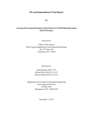
  • 38. Figure 13: Slope Movement at SHL 4 Question 2 on the checklist related to the prevalence of slope movements on the downstream face. Two sites were found to have moderate slope movements, and severe slope movements were present on six sites. Figure 13 shows a severe slope movement on the SHL 4 Centralized Pit. Above the slope movement, there was a significant amount of standing water on the crest, and signs of seepage were found in the form of wet soil inside the depleted soil zone. Slope movements are a problem because the structural integrity of the downstream face has been compromised. This slope failure is an example of a shallow face failure with characteristics including a pronounced scarp, zones of depletion and accumulation, and flanks defining the width of the failed soil, which is approximately where the WVU field personnel are located. ETD-10 Pits and Impoundments Final Report Page 38
  • 39. Figure 14: Woody Debris at SHL 2 Question 5 was used to evaluate any observed trees, tall weeds, or other vegetation, but the most prevalent concern was woody debris found in the fill of the slopes on all but two sites. Figure 14 depicts one instance of woody debris found on the SHL 2 Centralized Pit, where a log was compacted into the fill material on the downstream face of the pit. Woody debris is a problem due to the complications that may arise over time. One possible consequence is that the woody debris may form a barrier preventing the infiltration of water into the soil, causing erosion around the woody debris and on the slope directly below the debris. Another possible consequence is that the decomposition of the woody debris may result in pathways for surface water to seep into the slope, which reduces slope stability. ETD-10 Pits and Impoundments Final Report Page 39
  • 40. Figure 15: Seepage at Pribble Seepage and wet zones (addressed in Question 6) were problem areas found at all but two sites. Figure 15 shows a seepage area on the downstream face of the Pribble Freshwater Impoundment. Due to the lack of vegetation on the slope, the area where the grass is growing depicts seepage and moving water on the slope. Thus, water is being transported through the soil, which may lead to instability in this area. ETD-10 Pits and Impoundments Final Report Page 40
  • 41. Figure 16: Liner Bulges at MWV Another area of concern was bulges, tears, or holes in the liner, as indicated by Question 8. This problem was present at every site evaluated, with seven sites ranked as Low, four ranked as Moderate, and three ranked as High. Figure 16 depicts a liner stretched over an improperly prepared slope at the MWV Large Water Storage Pond 1. The underlying rock pressing on the liner and the strain caused by the bulges have a high likelihood to create tears or punctures in the liner and threaten the integrity of the containment system. ETD-10 Pits and Impoundments Final Report Page 41
  • 42. Figure 17: Debris on Liner at Flanigan Question 10 involved the presence of rock or debris on top of the liner. This problem was observed at all sites except one. Figure 17 illustrates an example of a severe case of debris on the liner at the Flanigan Pit. At the Flanigan Pit as well as other sites visited, surface water was present on the berm and in the anchor trench. This practice is not in accordance with the West Virginia Erosion and Sediment Control Field Manual, which states that surface water must be diverted from the pit. The water washing the rock and debris into the pit adds weight to the containment system which can lead to strain and dislodgement of the anchor trench. Also, with the rock washing down over the liner, there is a higher potential for tears to form. ETD-10 Pits and Impoundments Final Report Page 42
  • 43. Figure 18: Improper Anchor Trench Embedment at Ball 1H Deformations, cracks, and settlements around the anchor trench affect the integrity of the liner, and these concerns were addressed in Question 12 of the observation checklist. During field evaluations, this question was expanded to include the embedment of the anchor trench. All sites with the exception of one were found to have issues related to the anchor trench. Figure 18 illustrates improper anchor trench embedment at the Ball 1H Impoundment #2, as indicated by the liner protruding out of the ground. Improper embedment may result in an increased likelihood of the anchor trench pulling out of the soil, affecting the ability of the liner to retain fluids. Another potential issue is the possibility of wind lifting the liner and causing tears leading to a failure of the containment system. ETD-10 Pits and Impoundments Final Report Page 43
  • 44. Figure 19: Unsupported Pipe at Plum Creek The last observed trend was unsupported pipes. Question 14 addressed this concern, and pipes were not properly supported on eight of the fourteen sites. Figure 19 depicts a severe instance at the Plum Creek South Fork Impoundment. At this site, the pipe was unsupported along the crest of the impoundment and the adjoining hillside, hanging across a depression. Associated areas of concern include the pipe having the freedom to roll or slide, the possibility of the pipe buckling or pinching and restricting flow, and the increased potential for gouges and leakage. Any leakage or rupture of the pipes which convey water or flowback fluids would have an environmental impact to the surface water and groundwater. ETD-10 Pits and Impoundments Final Report Page 44
  • 45. Table 6 shows the score for each site, ranked from lowest to highest. The Donna Completion Impoundment received the lowest score among all sites visited. Of the three sites constructed after the enactment of the Natural Gas Horizontal Well Control Act §22-6A, two sites (SHL 2 and SHL 3) were among the sites receiving the highest scores, although SHL 4 received a low score due to a slope failure on the downstream face. As a result, slope failures may be an issue for SHL 2 and SHL 3 in the future. Site # Site Name Score 1 Donna Completion Impoundment 59.2% 2 Mills-Wetzel Freshwater Impoundment 68.4% 3 Pribble Freshwater Impoundment 72.4% 4 MWV Large Water Storage Pond 1 75.0% 5 SHL 4 Centralized Pit 76.3% 6 Ball 1H Impoundment #2 77.6% 7 Plum Creek South Fork 77.6% 8 MIP Freshwater Impoundment 80.3% 9 Larry Pad 82.9% 10 Donna Completion Pit 84.2% 11 Flanigan Pit 85.5% 12 Burch Ridge Wastewater Pit 88.2% 13 SHL 2 Centralized Pit 88.2% 14 SHL 3 Centralized Pit 88.2% Table 6: Summary of Site Scores While certain sites evaluated were known to have problems prior to the field evaluations, a visit to the Shields FWI site illustrated that current construction practices were characteristic of the problem areas observed in all the site visits. Thus, poor construction methods may be an initiator of the problems observed in the field. As an illustration of the construction practices at the Shields FWI site, pictures collected during the visit are presented. ETD-10 Pits and Impoundments Final Report Page 45
  • 46. Figure 20: Improper Compaction Practices In Figure 20, the excavator is placing the lift of soil, and the lift is being compacted by a sheepsfoot roller, followed by a vibratory roller. According to the West Virginia Erosion and Sediment Control Field Manual, each lift shall be compacted by compaction equipment, sheepsfoot or pad roller, with compaction to visible non-movement of the embankment material. Thus, the use of both a sheepsfoot roller and a vibratory roller violates the best management practice in the manual. This construction practice is creating a shear plane on which water can move through the soil, possibly resulting in a slope failure. The sheepsfoot roller kneads the soil, interlocking the soil lifts and benefiting compaction efforts, but the vibratory roller is negating this interlocking by smoothing the soil. ETD-10 Pits and Impoundments Final Report Page 46
  • 47. Figure 21: Woody Debris in Soil Lift Figure 21 depicts woody debris that has been compacted into the fill, which was a recurring area of concern on a majority of the sites evaluated. The West Virginia Erosion and Sediment Control Field Manual states that the fill material shall be clean mineral soil, free of roots, woody vegetation, stumps, sod, large rocks, or other objectionable material. As Figure 21 shows, this best management practice is not being followed at the Shields FWI site. Organic material compacted into the fill may create pathways for water to infiltrate the soil and cause internal erosion, which is a possible failure mode for the structure. ETD-10 Pits and Impoundments Final Report Page 47
  • 48. Figure 22: Excessive Lift Thickness According to the West Virginia Erosion and Sediment Control Field Manual, soil lifts must be as thin as the suitable random excavated material will permit, typically from 6 to 12 inches. In Figure 22, the lift thickness is 16 inches, so this construction practice is not in accordance with the best management practice specified in the manual. ETD-10 Pits and Impoundments Final Report Page 48
  • 49. 6.2 Questionnaire Responses Once the evaluation of the site conditions was completed, the Site Operations and Infrastructure Evaluation was conducted. This evaluation consisted of questions for the WVDEP Office of Oil and Gas Inspector on site and/or the company representative. However, the company personnel present at the time of the field visit may or may not have been the principle site inspectors. The questionnaire covered the inspector training and background in regards to pit and impoundment safety, the operation and maintenance procedures for the site, and safety plans such as Emergency Action Plans (EAPs). The responses to the questionnaire are contained within the appropriate sites’ Appendices. By comparing the responses across all sites, several conclusions were made about the overall inspection, operation, and maintenance of these structures. Questions 1 and 11 concerned the type and frequency of company site inspections performed by field personnel and Professional Engineers (PEs). The responses from WVDEP inspectors and company representatives varied from every three days to once every two months. Thus, there is no set frequency for site inspections to be performed at pits and impoundments. Infrequent inspections allow for problem areas to progress and may lead to failure if the problems are not addressed in a timely manner. Another concern is the varied responses for the frequency of site inspections by a PE, which ranged from weekly to never. The PE for the site may offer additional insight into the site conditions, so irregular visits may result in problem areas going unnoticed or a delay in the implementation of corrective actions. The background and type of training that the site inspectors possessed was the focus of Questions 2 and 3. A majority of the WVDEP inspectors had prior oil and gas industry experience, but neither the WVDEP inspectors nor the company representatives had any background in regards to the inspection of structures that impound water. Despite this lack of experience, the inspectors had not received any type of formal training. As a result, the inspectors may not fully understand how to identify problem areas that need to be addressed or the possible consequences associated with those issues. This lack of training may have significant impacts on the safety of the structure at all stages from construction through reclamation. In addition to the lack of training for inspectors, the site inspection procedures were also found to contribute to the areas of concern observed during field evaluations. Responses to Questions 4 and 5 revealed that no standardized form existed for the WVDEP inspectors to refer to during inspections, which resulted in the inspectors using state regulations as a guide. Furthermore, the inspectors only focused on readily apparent problems such as slips and slides, while not recognizing the smaller issues such as tension cracks and slope deformation that may lead to large-scale problems. ETD-10 Pits and Impoundments Final Report Page 49
  • 50. Another important aspect of pit and impoundment safety is the development of safety and emergency plans, which was covered in Questions 6, 7, 8, 9, and 10. While the majority of sites had safety plans covering the normal daily operations, only four sites had plans in place in the event of an emergency. Emergency Action Plans (EAPs) were not required before the enactment of the Natural Gas Horizontal Well Control Act §22-6A, and under the new law, only centralized pits and impoundments are required to develop EAPs. As a result, the only sites evaluated in this study which were required to have EAPs were the SHL 2, SHL 3, and SHL 4 Centralized Pits. The company representative at the SHL sites was not aware that an EAP existed, was not trained on the EAP, and did not know whether the EAP had been evaluated for practicality in the event of an emergency. In addition, the EAP was not available on-site during the field evaluation. As a result, the company representative was unprepared to respond to an emergency, which could lead to the endangerment of lives or the destruction of property. In the EAP for the SHL sites, no evacuation protocol was provided, with the following justification: “Due to the location of the pit described in this plan, no evacuation will be necessary in any case. The pit is a temporary structure that is fully incised in existing ground and that will be reclaimed once the Marcellus drilling in the surrounding region is complete. There are no nearby structures or facilities that would be affected by its breach or failure.” While the location of the pit may be remote, no inundation maps are provided in the EAP to support this statement. The SHL site also exhibited a slope failure as referenced in Figure 13. The incorporation of these maps would increase awareness of the full extent of the damage resulting from a failure and possibly highlight endangered areas that were not previously considered. Therefore, the addition of inundation maps to EAPs for all pits and impoundments constructed after the enactment of §22-6A would facilitate emergency planning for the structures. Additionally, the development of EAPs for all pits and impoundments, including those already constructed, would further benefit the safety of these structures and the surrounding areas. ETD-10 Pits and Impoundments Final Report Page 50
  • 51. 6.3 Laboratory Testing Results Once the laboratory testing was completed, the results from the various tests were compiled into tables and graphs in order to present the results in a convenient manner. Figure 23 illustrates the results of the Atterberg limits testing for each site. The range of moisture content values between the Plastic Limit (PL) and Liquid Limit (LL) is shown for each site, and the field moisture content is graphed as an illustration of the soil condition at the site. These values are displayed numerically in Table 7, where the results from the grain-size distribution and Atterberg limits tests for each site were used to classify the soil according to the ASTM D2487 Standard. According to the WVDEP Design and Construction Standards for Centralized Pits, the following soil classifications are acceptable for post §22-6A sites: Clayey Gravel (GC), Silty Gravel (GM), Clayey Sand (SC), Silty Sand (SM), Clay (CL), and Silt (ML). The laboratory testing results indicated that none of the post §22-6A sites met this requirement, and of the remaining 12 pre §22-6A sites, only one site met the soil standards. ETD-10 Pits and Impoundments Final Report Page 51
  • 52. Site Moisture Content PL LL Figure 23: Atterberg Limits and Field Moisture Content ETD-10 Pits and Impoundments Final Report Page 52
  • 53. Table 7: Soil Classification ETD-10 Pits and Impoundments Final Report Page 53
  • 54. In addition to the classification testing, further soil testing was performed on six sites. During the field visits to these sites, WVU subcontractor Potesta and Associates, Inc. collected in situ field compaction and moisture content data using a nuclear density gauge. Readings were taken at various locations on each site, including the crest, mid-slope, and toe of the downstream face. Furthermore, WVU researchers collected two additional buckets of soil on these sites in order to perform laboratory compaction, hydraulic conductivity, and strength testing on the soil. After performing the laboratory compaction tests for each of the six sites, a graph was generated showing the relationship between the dry density of the soil and the moisture content. Thus, the optimum dry density and moisture content for each site were determined. Saturation curves depicting the values where the soil was 100% and 90% saturated were computed using the 𝐺𝑠 𝛾 𝑤 following equation: γd = ωG 1 + ( s) S In this equation, 𝐺 𝑠 is the specific gravity of the soil, as determined by the laboratory testing performed at WVU. 𝛾 𝑤 is the unit weight of water, which is 62.4 lb/ft3; ω is the moisture a percentage. Entering these values into the equation yielded a range of dry densities (γd ), content of the soil, for which a range of values was used in accordance with the observed moisture contents at the site; and S is the degree of saturation, expressed as a decimal rather than which were plotted on the compaction graph. To better illustrate this procedure, a sample table showing the results of these calculations for the Mills-Wetzel Freshwater Impoundment is shown in Table 8. S = 100% Moisture Content (%) Specific Gravity Water Density (lb/ft3) Dry Density (lb/ft3) 6 2.78 62.4 148.67 8 2.78 62.4 141.91 10 2.78 62.4 135.74 12 2.78 62.4 130.08 14 2.78 62.4 124.87 16 2.78 62.4 120.07 18 2.78 62.4 115.62 20 2.78 62.4 111.49 22 2.78 62.4 107.64 Table 8: Saturation Calculations ETD-10 Pits and Impoundments Final Report Page 54
  • 55. The West Virginia Erosion and Sediment Control Field Manual requires that soil lifts shall be compacted to a standard Proctor density of at least 95% and that compaction effort shall not exceed optimum moisture contents. In order to compare the adherence of site construction practices to this standard, a standard Proctor density of 95% of the optimum dry density was computed for each site. To achieve proper compaction on-site, the moisture content should be on the dry side of the optimum moisture content. Therefore, the appropriate compaction density and moisture content range was plotted on the graphs, signified by red lines. Lastly, the field data obtained by the nuclear density gauge readings was organized by the location of the reading (crest, mid-slope, toe) and graphed to determine how the field compaction compared with the laboratory results. The graphs for the Mills-Wetzel Freshwater Impoundment and the Larry Pad are presented in Figures 24 and 25, respectively, while the graphs for the remaining sites are contained in the corresponding Appendices. ETD-10 Pits and Impoundments Final Report Page 55
  • 56. Figure 24: Mills-Wetzel Compaction ETD-10 Pits and Impoundments Final Report Page 56
  • 57. Figure 25: Larry Compaction ETD-10 Pits and Impoundments Final Report Page 57
  • 58. The compaction results show that the soils on the crests tended to be overcompacted, which would render the point on the wet side of optimum if compared with a higher compaction energy. Also, the soils at the mid-slopes and toes of the downstream faces were consistently under-compacted and contained moisture content values higher than optimum. As a result, the soils at these locations exhibited high saturation values. These conditions may result in lower unit weight and strength for the soil, leading to a higher potential for slope deformation, internal erosion, and seepage. These observations were found to be trends across all sites, as only three of the six sites contained data points within the appropriate compaction range. Only 14% of field data points were in compliance at two of the sites, and 22% were in compliance at the third site. Overall, a total of seventy data points were taken across all six sites, and only six points were within the acceptable compaction range, which corresponds to 8.5% compliance with WVDEP standards. Table 9 further illustrates these trends by comparing the optimum moisture content and density with the ranges observed in the field for each site. Based on these findings, the compaction practices at the sites evaluated do not conform to the best management practices specified in the West Virginia Erosion and Sediment Control Field Manual. ETD-10 Pits and Impoundments Final Report Page 58
  • 59. Optimum Optimum Field Minimum Maximum Minimum Maximum Site Name Moisture Density Moisture Moisture Moisture Density Density Content (lb/ft3) Content Content Content (lb/ft3) (lb/ft3) MIP Freshwater 17.2% 113.8 16.83% 11.5% 25.5% 72.0 112.6 Impoundment Ball 1H 15.6% 117.5 22.91% 14.8% 22.7% 95.9 113.1 Impoundment #2 Mills-Wetzel Freshwater 12.2% 121.5 20.14% 10.2% 20.6% 97.8 122.4 Impoundment SHL 2 13.7% 122.1 20.83% 7.1% 20.7% 86.3 109.5 Centralized Pit SHL 3 13.7% 122.1 20.83% 6.5% 37.9% 88.0 115.5 Centralized Pit SHL 4 13.7% 122.1 20.83% 11.4% 23.5% 89.1 120.4 Centralized Pit Flanigan Pit 15.8% 114.5 25.39% 12.2% 18.5% 108.9 123.1 Larry Pad 11.7% 117.8 16.19% 6.9% 19.9% 103.2 132.5 Table 9: Laboratory and Field Moisture Content and Compaction Results ETD-10 Pits and Impoundments Final Report Page 59
  • 60. Once the Standard Proctor testing was completed, hydraulic conductivity and shear strength testing was performed. The hydraulic conductivity testing consisted of preparing two samples for each site, one compacted at the field moisture content and one compacted at the optimum moisture content determined by laboratory testing. After the hydraulic conductivity was determined, the sample compacted at the optimum moisture content was used for shear strength testing to obtain the internal angle of friction (𝜙). The results of these tests are contained in the appropriate site Appendices and are summarized in Table 10. Friction ( 𝜙) ASTM Soil Hydraulic Conductivity Angle of Site Name Classification Field (cm/s) Lab (cm/s) MIP Freshwater Impoundment SW-SC 3.0E-08 7.0E-08 40.2° Ball 1H Impoundment #2 SC 6.4E-08 2.2E-08 43.7° Mills-Wetzel Freshwater Impoundment SW-SC 2.8E-08 2.0E-08 40.6° SHL Centralized Pits SP 1.5E-08 2.0E-08 40.2° Flanigan Pit SW-SC 1.2E-08 4.4E-09 42.6° Larry Pad SW 1.3E-08 1.8E-08 40.7° Table 10: Hydraulic Conductivity and Friction Angle The hydraulic conductivity values obtained were comparable between the field and laboratory conditions at each site. The differences in the values are attributed to the moisture contents under which the soils were prepared. The internal friction angles obtained indicate that the soils have high shear strength potential. Although the Ball 1H Impoundment #2 was the only site that contained soil conforming to the post §22-6A soil classification types specified by the WVDEP, these results indicate that the site soils are adequate if proper compaction is achieved. Therefore, the WVDEP should review the acceptable soil types specified in the WVDEP Design and Construction Standards for Centralized Pits. After the completion of the laboratory testing at WVU, a comparison was made between the results obtained in the laboratory and the geotechnical investigations performed prior to the construction of the pit or impoundment. Since several permits lacked geotechnical investigation reports or were not provided at the time of the evaluation, the WVDEP permits that contained geotechnical investigations were analyzed. As an example, the review of the SHL 3 Centralized Pit is presented. According to the SHL 3 permit, three boring holes were drilled at opposite ends and in the middle of the pit to evaluate the subsurface conditions at the site. The test borings were drilled to depths ranging from 26 feet to 42 feet, which corresponded to depths of five feet to 20 feet below the final elevation of the bottom of the pit. The results of the borings indicate that clay was found at the site to a depth of eight feet and that bedrock was found underlying the clay. Laboratory testing was performed on representative samples of the clay soil and soft bedrock, ETD-10 Pits and Impoundments Final Report Page 60
  • 61. and the specific tests conducted were field moisture content, Atterberg limits, grain-size distribution, standard Proctor, and hydraulic conductivity. The laboratory results in the permit contained values differing from those obtained through the testing performed at WVU for the SHL 3 Centralized Pit. The results from the three boring holes are compared with the results obtained by WVU in Table 11. Property Permit Results WVU Results Field Moisture Content 12.9% - 19.7% 20.83% Plasticity Index 14 - 21 9.8 Soil Classification Clay (CL) Poorly Graded Sand (SP) Optimum Density (lb/ft3) 108.1 - 115.0 122.1 Optimum Moisture Content 14.7% - 17.6% 13.7% Hydraulic Conductivity (cm/s) 5.8E-08 1.5E-08 Table 11: Comparison of Permit to WVU Laboratory Results for SHL 3 The reason for the discrepancies between the laboratory results may be linked to the field sampling procedures. According to the boring logs and testing results in the SHL 3 permit, the soil samples used for the engineering properties testing were taken from a depth of zero feet to five feet. The natural elevation of the site ranged from 1,308 feet to 1,325 feet, and the bottom of the pit was excavated to slope from elevation 1,298 feet to 1,294 feet. As a result, the soil from the top five feet of the excavation may not be representative of the fill material used to construct the bottom of the pit, the upstream faces, and the downstream faces. This observation may be supported by the testing performed on soil from a depth of 10 feet to 15 feet in one of the boring holes. While this soil was not classified, the optimum density was found to be 117.1 lb/ft3, which is closer to the 122.1 lb/ft3 determined by the testing performed by WVU personnel. Also, the optimum moisture content for this soil was 13.7%, which is in agreement with the optimum moisture content found by WVU for the site. Thus, the fill soil exhibits engineering properties that differ from those obtained by testing the top layers of the site soil prior to construction, which may be another factor contributing to the post-construction issues observed during the field evaluations. By expanding the geotechnical investigations to include the soils at pit depth, the appropriate engineering properties for the fill soil can be determined, thereby benefiting the overall stability of the pit or impoundment. ETD-10 Pits and Impoundments Final Report Page 61
  • 62. 7.0 West Virginia Dam Safety While the pits and impoundments evaluated in this study are not classified as dams, the quantities of fluids impounded by these structures are comparable to the storage volumes of dams. According to the Dam Control and Safety Act – WV Code 22-14 and the Dam Safety Rule (47CSR34), Sections 3.2 a and c denote that for incised reservoirs the volume of water retained below ground surface is not included in determining whether the pit or impoundment meets the dam criteria. Table 12 contains the permitted storage volume for each site evaluated in the study. No site met the designation for status as a dam per the Dam Control and Safety Act. Site Name Permit Volume (Acre-Feet) WV Dam Status Donna Completion Impoundment N/A N/A Mills-Wetzel Freshwater Impoundment ~20.56 No Pribble Freshwater Impoundment 37.83 No MWV Large Water Storage Pond 1 55.98 No SHL 2 Centralized Pit 12.07 No SHL 3 Centralized Pit 11.47 No SHL 4 Centralized Pit 12.39 No Ball 1H Impoundment #2 23.28 No Plum Creek South Fork 45.85 No MIP Freshwater Impoundment 7.32 No Larry Pad N/A N/A Donna Completion Pit 7.81 No Flanigan Pit 12.41 No Burch Ridge Wastewater Pit 11.19 No Table 12: Comparison of Storage Volumes and Dam Requirements The permit file for the Donna Completion Impoundment was not provided, and the permit file for the Larry Pad did not contain the storage volume; thus, no determination could be reached regarding these structures. ETD-10 Pits and Impoundments Final Report Page 62
  • 63. 8.0 Conclusions and Recommendations The goals of this study were to conduct engineering reviews of submitted and approved permit plans, construction practices, and geotechnical investigations of pits and impoundments associated with Marcellus Shale horizontal gas wells. The overall purpose was to ascertain and document the suitability of the construction and use of these structures in minimizing the potential environmental effects related to horizontal drilling. After obtaining the permits for various pits and impoundments from the WVDEP, engineering reviews revealed areas of concern. The permit files provided to WVU researchers for 10 sites constructed prior to the enactment of the Natural Gas Horizontal Well Control Act §22-6A lacked geotechnical investigations. However, the permits for the three post §22-6A sites contained geotechnical information. Also, the WVDEP did not provide the permits for two sites at the time of the evaluation. An analysis of the permits compared the permitted storage volumes with the storage volume requirements of dams as regulated by the WVDEP (WVCSR §22-14 & WVCSR §47-34). No sites were found to meet the requirements of a dam. However, the large quantities of water could be a potential hazard to the public and the environment if a failure were to occur because of the ridge-top location of several sites. While issues were found in the development of the permits for the pits and impoundments, further concerns were observed during the field evaluations of the construction practices for these structures. The as-built construction dimensions were inconsistent with those found in the permit, including larger capacities, smaller berm widths, and steeper slopes than the permitted designs specified. These discrepancies create unknown stresses on the structure that may lead to instability. Additionally, quality control and assurance were found to be lacking during the construction of the structures, with no field compaction standards, improper soil types, excessive slope lengths, insufficient erosion control, and buried debris. Furthermore, the placement of pipelines and geosynthetic liners was found to be inconsistent with industry practices, posing potential safety and environmental concerns. Any leakage or rupture of the pipes or liner systems would have an adverse environmental impact to the surface water and groundwater. Therefore, the best management practices set forth by the WVDEP are not being adhered to throughout the construction process for pits and impoundments. A stricter application of WVDEP best management practices and an increased quality assurance and control process during construction and operation are recommended to significantly improve the long-term safety of these structures by mitigating possible problems. ETD-10 Pits and Impoundments Final Report Page 63