SlideShare une entreprise Scribd logo
1  sur  3
Télécharger pour lire hors ligne
A proper safety valve installation with a drip
pan elbow and proper drain lines off the
safety valve and drip pan elbow.
New installation of the vent pipe - proper
supports are being installed
STEAM SYSTEMS BEST PRACTICES
Swagelok Energy Advisors, Inc.	 Document No. 17
One of the most critical automatic safety devices in a steam system is the safety valve. The
safety valve provides a protective measure for lives, equipment, and property from potentially
dangerous levels of temperature and forces caused by excessive steam pressure in a system.
Safety valves are required by code and insurers. Therefore, it is important to have good,
up-to-date records of all safety valves in the steam system. With today’s readily available
technology, a database should be developed containing all the relative information of all
safety devices in a facility. The safety valve database should be reviewed on a periodic basis
depending on plant standards, insurance company recommendations, and the local, state,
or federal government requirements.
The code that establishes the requirements for safety valves is governed by the American
Society of Mechanical Engineers (ASME). Through its committees, ASME has published and
continues to update the Boiler and Pressure Vessel codes for safety valves. It is the respon-
sibility of plant personnel, primarily the steam team, to know which codes apply to the
different parts of the steam system.
In the United States the major considerations for safety valves are proper sizing followed by
correct installation. A partial listing of sizing and installation highlights is listed below. More
guidelines will be provided in future articles.
Sizing Guidelines for Safety Valves
	 • The set point for the safety valve is suggested to provide a differential between
	 operating and set steam pressures of at least 20 %.
	
	 • When considering a safety valve downstream of a steam pressure control valve,
	 the total capacity of the safety valve at the set point must exceed the steam control
	 valve’s maximum flow capacity (largest orifice available from that manufacturer) if
	 the steam valve were to fail open. The inlet steam pressure to the valve must be
	 calculated at the maximum safety valve setting of the steam supply source, not the
	 nominal operating pressure.
	
	
SWAGELOK ENERGY ADVISORS, INC. | WWW.SWAGELOKENERGY.COM | 888-615-3559 | SEATECHNICALSERVICE@SWAGELOK.COM
Best Practices for
Installation of Safety Valves
By Kelly Paffel Technical Manager Swagelok Company
SWAGELOK ENERGY ADVISORS, INC. | WWW.SWAGELOKENERGY.COM | 888-615-3559 | SEATECHNICALSERVICE@SWAGELOK.COM
	 • It is important not to oversize a safety valve. Bigger is not better in this 	
		 case because a larger than required valve could cause chatter, leakage, 	
		 and premature failure, of safety.
	
	 • Many times, a single safety valve is not possible due to high capacity,
	 physical limitations, or economic considerations. An acceptable alterna-	
	 tive method is to employ multiple safety valves on the same system. The 	
	 valves should be of the same set point and the capacities must be equal 	
	 to or greater than the rating of the equipment. Additionally, the vent pipe	
	 must be sized to account for the venting capacity of all the safety valves 	
	 fully opening at the same time.
	 • The set pressure of the safety valve shall be set at or below the Maxi	-	
		 mum Allowable Working Pressure (MAWP) of the component with the	
		 lowest set point in the system. This includes but is not limited to steam 	
		 boilers, pressure vessels and equipment, and piping systems. In other 	
		 words, if two components on the same system are rated at different 	
		 pressures, the safety device protecting both of these devices must be set 	
		 at the lower of the two ratings.
Installation
	 • The steam system must be clean and free of any dirt or sediment before
	 commissioning the steam system with a safety valve.
	
	 • The safety valve must be mounted vertically with the valve’s spindle in
	 the vertical position.
	 • The inlet steam piping to the safety valve must be equal to or larger
	 than the safety valve inlet connection.
	 • There shall be no intervening shut-off valves located between the safety 	
		 valve inlet and the steam component that could permit the safety valve to 	
		 be isolated from the system.
	
	 • Drains or vent openings on the safety valve shall not be plugged or 		
		 capped. They are on the safety valve for a reason.
	 • Safety valves are set, sealed, and certified to prevent tampering. If the 	
		 wire seal is broken, the valve is unsafe and should not be used. Contact 	
		 the supplier immediately.
	 • For multiple safety valve installations using a single connection, the inter-	
		 nal cross-sectional area of the inlet shall be equal to the combined inlet
	 areas of all the safety valves.
STEAM SYSTEMS BEST PRACTICES
Swagelok Energy Advisors, Inc.	 Document No. 17
Safety valve is not installed vertically.
Safety valve installation with proper
drains and drip pan elbow.
SWAGELOK ENERGY ADVISORS, INC. | WWW.SWAGELOKENERGY.COM | 888-615-3559 | SEATECHNICALSERVICE@SWAGELOK.COM
Swagelok – TM Swagelok Company © 2009 Swagelok Company
	 • All safety valves should use a drip pan elbow on the outlet. The drip pan 	
		 elbow changes the outlet of the safety device from horizontal to vertical. 	
		 Installation of the drip pan elbow has its own guidelines.
		 o Never attach the vent discharge piping directly to the 		
		 safety valve. This would place undue stress and weight on 		
		 the valve body.
		 o The safety valve vent pipe may not touch the drip pan elbow
		
		 o The drains on the drip pan elbows are to direct condensed 	
		 vapor and rain safely away to the drain. Do not plug these 		
		 openings.
		
		 o Steam will not escape from the drip pan elbow if the vent line 	
			 is sized correctly.
	 • Vent piping
		 o The diameter of the vent pipe must be equal to or greater 		
		 than the safety valve outlet.
		 o The vent line should be sized such that back pressure is not 	
		 placed on the drip pan elbow.
			
		 o Minimize the length of the vent pipe.
		 o The discharge outlet of the vent pipe should be piped to 		
		 the closest location where free discharge of the safety device 	
		 will not pose a safety hazard to personnel. For a roof line 		
		 termination, the vent should be no less than seven (7) feet 		
		 above roof line. The top of the vent line should be cut at 		
		 a 45 degree angle to dissipate the discharge thrust of the 		
		 steam, prevent capping of the pipe, and to visually signify 		
		 that it is a safety valve vent line.
	 The proper selection, installation, and use of safety valves requires a com-	
	 plete understanding of ASME code and any additional requirements adopt-	
	 ed by insurance companies or the local jurisdictional authority.
STEAM SYSTEMS BEST PRACTICES
Swagelok Energy Advisors, Inc.	 Document No. 17
Best Practices
	 1. Database all safety valves.
	 2. All safety valves should be reviewed
	 on a periodic basis depending on plant
	 standards, insurance company recom 	 	
mendations, and local, state, or federal
	 government requirements.
	 3. Institute plant standards for safety valve
	 selection and installation.

Contenu connexe

Tendances

Tendances (6)

Case Study: Refinery Relief and Flare Study
Case Study: Refinery Relief and Flare StudyCase Study: Refinery Relief and Flare Study
Case Study: Refinery Relief and Flare Study
 
EESS 2018 Day 1 - Tim Webster
EESS 2018 Day 1 - Tim WebsterEESS 2018 Day 1 - Tim Webster
EESS 2018 Day 1 - Tim Webster
 
Improving reliability thru automation projects r4
Improving reliability thru automation projects r4Improving reliability thru automation projects r4
Improving reliability thru automation projects r4
 
Gates advantage Hydraulic Hose and Couplings
Gates advantage Hydraulic Hose and CouplingsGates advantage Hydraulic Hose and Couplings
Gates advantage Hydraulic Hose and Couplings
 
Safe Hose Assemble: From Factory to Field
Safe Hose Assemble: From Factory to FieldSafe Hose Assemble: From Factory to Field
Safe Hose Assemble: From Factory to Field
 
Kystal Clear Model 603 filter pump Manual for Intex Pools
Kystal Clear Model 603 filter pump Manual for Intex PoolsKystal Clear Model 603 filter pump Manual for Intex Pools
Kystal Clear Model 603 filter pump Manual for Intex Pools
 

Similaire à Es installation of safety valves bp-17

ValveSentry Automatic Water Shut Off Valve Device Prevents Basement Floods
ValveSentry Automatic Water Shut Off Valve Device Prevents Basement FloodsValveSentry Automatic Water Shut Off Valve Device Prevents Basement Floods
ValveSentry Automatic Water Shut Off Valve Device Prevents Basement Floods
Battic Door Energy Conservation Products
 
RWC, Reliance Water Controls - Heatguard Bar Shower
RWC, Reliance Water Controls - Heatguard Bar ShowerRWC, Reliance Water Controls - Heatguard Bar Shower
RWC, Reliance Water Controls - Heatguard Bar Shower
Thorne & Derrick UK
 
Sealweld commissioning enhancement
Sealweld commissioning enhancementSealweld commissioning enhancement
Sealweld commissioning enhancement
kokan007
 
Littelfuse fuseology selection_guide.pdf
Littelfuse fuseology selection_guide.pdfLittelfuse fuseology selection_guide.pdf
Littelfuse fuseology selection_guide.pdf
Brit4
 
Waterwise Garden Irrigator Program - Australia
Waterwise Garden Irrigator Program - AustraliaWaterwise Garden Irrigator Program - Australia
Waterwise Garden Irrigator Program - Australia
Kaila694m
 

Similaire à Es installation of safety valves bp-17 (20)

8013 _0
8013  _08013  _0
8013 _0
 
PSV Sizing.pdf
PSV Sizing.pdfPSV Sizing.pdf
PSV Sizing.pdf
 
Parcol-PSV handbook by parcel engineering
Parcol-PSV handbook by parcel engineeringParcol-PSV handbook by parcel engineering
Parcol-PSV handbook by parcel engineering
 
Pressure Safety Valve Sizing - API 520/521/526
Pressure Safety Valve Sizing - API 520/521/526Pressure Safety Valve Sizing - API 520/521/526
Pressure Safety Valve Sizing - API 520/521/526
 
ASCO - Solenoid Valves - Oil & Gas Industry Brochure
ASCO - Solenoid Valves - Oil & Gas Industry BrochureASCO - Solenoid Valves - Oil & Gas Industry Brochure
ASCO - Solenoid Valves - Oil & Gas Industry Brochure
 
Hose
HoseHose
Hose
 
Hydraullically assisted pressure relief valve service sheet
Hydraullically assisted pressure relief valve service sheetHydraullically assisted pressure relief valve service sheet
Hydraullically assisted pressure relief valve service sheet
 
Bhel STEAM safety valve_1700_series
Bhel STEAM safety valve_1700_seriesBhel STEAM safety valve_1700_series
Bhel STEAM safety valve_1700_series
 
Safety Valves for Steam, Gases and Liquids
Safety Valves for Steam, Gases and LiquidsSafety Valves for Steam, Gases and Liquids
Safety Valves for Steam, Gases and Liquids
 
ValveSentry Automatic Water Shut Off Valve Device Prevents Basement Floods
ValveSentry Automatic Water Shut Off Valve Device Prevents Basement FloodsValveSentry Automatic Water Shut Off Valve Device Prevents Basement Floods
ValveSentry Automatic Water Shut Off Valve Device Prevents Basement Floods
 
Boiler recommissioning procedure after capital overhaul
Boiler recommissioning procedure after capital overhaul Boiler recommissioning procedure after capital overhaul
Boiler recommissioning procedure after capital overhaul
 
Consolidated power srvc_valves_brochure_0512
Consolidated power srvc_valves_brochure_0512Consolidated power srvc_valves_brochure_0512
Consolidated power srvc_valves_brochure_0512
 
Adams8031 00
Adams8031 00Adams8031 00
Adams8031 00
 
RWC, Reliance Water Controls - Heatguard Bar Shower
RWC, Reliance Water Controls - Heatguard Bar ShowerRWC, Reliance Water Controls - Heatguard Bar Shower
RWC, Reliance Water Controls - Heatguard Bar Shower
 
Sealweld commissioning enhancement
Sealweld commissioning enhancementSealweld commissioning enhancement
Sealweld commissioning enhancement
 
Boiler Mountings
Boiler MountingsBoiler Mountings
Boiler Mountings
 
Littelfuse fuseology selection_guide.pdf
Littelfuse fuseology selection_guide.pdfLittelfuse fuseology selection_guide.pdf
Littelfuse fuseology selection_guide.pdf
 
Waterwise Garden Irrigator Program - Australia
Waterwise Garden Irrigator Program - AustraliaWaterwise Garden Irrigator Program - Australia
Waterwise Garden Irrigator Program - Australia
 
GRI WVS Data Sheet
GRI WVS Data SheetGRI WVS Data Sheet
GRI WVS Data Sheet
 
Pressure Relief Devices
Pressure Relief DevicesPressure Relief Devices
Pressure Relief Devices
 

Dernier

Hospital management system project report.pdf
Hospital management system project report.pdfHospital management system project report.pdf
Hospital management system project report.pdf
Kamal Acharya
 
Integrated Test Rig For HTFE-25 - Neometrix
Integrated Test Rig For HTFE-25 - NeometrixIntegrated Test Rig For HTFE-25 - Neometrix
Integrated Test Rig For HTFE-25 - Neometrix
Neometrix_Engineering_Pvt_Ltd
 
1_Introduction + EAM Vocabulary + how to navigate in EAM.pdf
1_Introduction + EAM Vocabulary + how to navigate in EAM.pdf1_Introduction + EAM Vocabulary + how to navigate in EAM.pdf
1_Introduction + EAM Vocabulary + how to navigate in EAM.pdf
AldoGarca30
 

Dernier (20)

Hostel management system project report..pdf
Hostel management system project report..pdfHostel management system project report..pdf
Hostel management system project report..pdf
 
Introduction to Serverless with AWS Lambda
Introduction to Serverless with AWS LambdaIntroduction to Serverless with AWS Lambda
Introduction to Serverless with AWS Lambda
 
Wadi Rum luxhotel lodge Analysis case study.pptx
Wadi Rum luxhotel lodge Analysis case study.pptxWadi Rum luxhotel lodge Analysis case study.pptx
Wadi Rum luxhotel lodge Analysis case study.pptx
 
Orlando’s Arnold Palmer Hospital Layout Strategy-1.pptx
Orlando’s Arnold Palmer Hospital Layout Strategy-1.pptxOrlando’s Arnold Palmer Hospital Layout Strategy-1.pptx
Orlando’s Arnold Palmer Hospital Layout Strategy-1.pptx
 
COST-EFFETIVE and Energy Efficient BUILDINGS ptx
COST-EFFETIVE  and Energy Efficient BUILDINGS ptxCOST-EFFETIVE  and Energy Efficient BUILDINGS ptx
COST-EFFETIVE and Energy Efficient BUILDINGS ptx
 
data_management_and _data_science_cheat_sheet.pdf
data_management_and _data_science_cheat_sheet.pdfdata_management_and _data_science_cheat_sheet.pdf
data_management_and _data_science_cheat_sheet.pdf
 
Tamil Call Girls Bhayandar WhatsApp +91-9930687706, Best Service
Tamil Call Girls Bhayandar WhatsApp +91-9930687706, Best ServiceTamil Call Girls Bhayandar WhatsApp +91-9930687706, Best Service
Tamil Call Girls Bhayandar WhatsApp +91-9930687706, Best Service
 
GEAR TRAIN- BASIC CONCEPTS AND WORKING PRINCIPLE
GEAR TRAIN- BASIC CONCEPTS AND WORKING PRINCIPLEGEAR TRAIN- BASIC CONCEPTS AND WORKING PRINCIPLE
GEAR TRAIN- BASIC CONCEPTS AND WORKING PRINCIPLE
 
Hospital management system project report.pdf
Hospital management system project report.pdfHospital management system project report.pdf
Hospital management system project report.pdf
 
Computer Networks Basics of Network Devices
Computer Networks  Basics of Network DevicesComputer Networks  Basics of Network Devices
Computer Networks Basics of Network Devices
 
Unleashing the Power of the SORA AI lastest leap
Unleashing the Power of the SORA AI lastest leapUnleashing the Power of the SORA AI lastest leap
Unleashing the Power of the SORA AI lastest leap
 
Integrated Test Rig For HTFE-25 - Neometrix
Integrated Test Rig For HTFE-25 - NeometrixIntegrated Test Rig For HTFE-25 - Neometrix
Integrated Test Rig For HTFE-25 - Neometrix
 
Double Revolving field theory-how the rotor develops torque
Double Revolving field theory-how the rotor develops torqueDouble Revolving field theory-how the rotor develops torque
Double Revolving field theory-how the rotor develops torque
 
Online food ordering system project report.pdf
Online food ordering system project report.pdfOnline food ordering system project report.pdf
Online food ordering system project report.pdf
 
1_Introduction + EAM Vocabulary + how to navigate in EAM.pdf
1_Introduction + EAM Vocabulary + how to navigate in EAM.pdf1_Introduction + EAM Vocabulary + how to navigate in EAM.pdf
1_Introduction + EAM Vocabulary + how to navigate in EAM.pdf
 
Computer Lecture 01.pptxIntroduction to Computers
Computer Lecture 01.pptxIntroduction to ComputersComputer Lecture 01.pptxIntroduction to Computers
Computer Lecture 01.pptxIntroduction to Computers
 
HAND TOOLS USED AT ELECTRONICS WORK PRESENTED BY KOUSTAV SARKAR
HAND TOOLS USED AT ELECTRONICS WORK PRESENTED BY KOUSTAV SARKARHAND TOOLS USED AT ELECTRONICS WORK PRESENTED BY KOUSTAV SARKAR
HAND TOOLS USED AT ELECTRONICS WORK PRESENTED BY KOUSTAV SARKAR
 
Moment Distribution Method For Btech Civil
Moment Distribution Method For Btech CivilMoment Distribution Method For Btech Civil
Moment Distribution Method For Btech Civil
 
FEA Based Level 3 Assessment of Deformed Tanks with Fluid Induced Loads
FEA Based Level 3 Assessment of Deformed Tanks with Fluid Induced LoadsFEA Based Level 3 Assessment of Deformed Tanks with Fluid Induced Loads
FEA Based Level 3 Assessment of Deformed Tanks with Fluid Induced Loads
 
Thermal Engineering Unit - I & II . ppt
Thermal Engineering  Unit - I & II . pptThermal Engineering  Unit - I & II . ppt
Thermal Engineering Unit - I & II . ppt
 

Es installation of safety valves bp-17

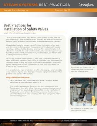
  • 1. A proper safety valve installation with a drip pan elbow and proper drain lines off the safety valve and drip pan elbow. New installation of the vent pipe - proper supports are being installed STEAM SYSTEMS BEST PRACTICES Swagelok Energy Advisors, Inc. Document No. 17 One of the most critical automatic safety devices in a steam system is the safety valve. The safety valve provides a protective measure for lives, equipment, and property from potentially dangerous levels of temperature and forces caused by excessive steam pressure in a system. Safety valves are required by code and insurers. Therefore, it is important to have good, up-to-date records of all safety valves in the steam system. With today’s readily available technology, a database should be developed containing all the relative information of all safety devices in a facility. The safety valve database should be reviewed on a periodic basis depending on plant standards, insurance company recommendations, and the local, state, or federal government requirements. The code that establishes the requirements for safety valves is governed by the American Society of Mechanical Engineers (ASME). Through its committees, ASME has published and continues to update the Boiler and Pressure Vessel codes for safety valves. It is the respon- sibility of plant personnel, primarily the steam team, to know which codes apply to the different parts of the steam system. In the United States the major considerations for safety valves are proper sizing followed by correct installation. A partial listing of sizing and installation highlights is listed below. More guidelines will be provided in future articles. Sizing Guidelines for Safety Valves • The set point for the safety valve is suggested to provide a differential between operating and set steam pressures of at least 20 %. • When considering a safety valve downstream of a steam pressure control valve, the total capacity of the safety valve at the set point must exceed the steam control valve’s maximum flow capacity (largest orifice available from that manufacturer) if the steam valve were to fail open. The inlet steam pressure to the valve must be calculated at the maximum safety valve setting of the steam supply source, not the nominal operating pressure. SWAGELOK ENERGY ADVISORS, INC. | WWW.SWAGELOKENERGY.COM | 888-615-3559 | SEATECHNICALSERVICE@SWAGELOK.COM Best Practices for Installation of Safety Valves By Kelly Paffel Technical Manager Swagelok Company
  • 2. SWAGELOK ENERGY ADVISORS, INC. | WWW.SWAGELOKENERGY.COM | 888-615-3559 | SEATECHNICALSERVICE@SWAGELOK.COM • It is important not to oversize a safety valve. Bigger is not better in this case because a larger than required valve could cause chatter, leakage, and premature failure, of safety. • Many times, a single safety valve is not possible due to high capacity, physical limitations, or economic considerations. An acceptable alterna- tive method is to employ multiple safety valves on the same system. The valves should be of the same set point and the capacities must be equal to or greater than the rating of the equipment. Additionally, the vent pipe must be sized to account for the venting capacity of all the safety valves fully opening at the same time. • The set pressure of the safety valve shall be set at or below the Maxi - mum Allowable Working Pressure (MAWP) of the component with the lowest set point in the system. This includes but is not limited to steam boilers, pressure vessels and equipment, and piping systems. In other words, if two components on the same system are rated at different pressures, the safety device protecting both of these devices must be set at the lower of the two ratings. Installation • The steam system must be clean and free of any dirt or sediment before commissioning the steam system with a safety valve. • The safety valve must be mounted vertically with the valve’s spindle in the vertical position. • The inlet steam piping to the safety valve must be equal to or larger than the safety valve inlet connection. • There shall be no intervening shut-off valves located between the safety valve inlet and the steam component that could permit the safety valve to be isolated from the system. • Drains or vent openings on the safety valve shall not be plugged or capped. They are on the safety valve for a reason. • Safety valves are set, sealed, and certified to prevent tampering. If the wire seal is broken, the valve is unsafe and should not be used. Contact the supplier immediately. • For multiple safety valve installations using a single connection, the inter- nal cross-sectional area of the inlet shall be equal to the combined inlet areas of all the safety valves. STEAM SYSTEMS BEST PRACTICES Swagelok Energy Advisors, Inc. Document No. 17 Safety valve is not installed vertically. Safety valve installation with proper drains and drip pan elbow.
  • 3. SWAGELOK ENERGY ADVISORS, INC. | WWW.SWAGELOKENERGY.COM | 888-615-3559 | SEATECHNICALSERVICE@SWAGELOK.COM Swagelok – TM Swagelok Company © 2009 Swagelok Company • All safety valves should use a drip pan elbow on the outlet. The drip pan elbow changes the outlet of the safety device from horizontal to vertical. Installation of the drip pan elbow has its own guidelines. o Never attach the vent discharge piping directly to the safety valve. This would place undue stress and weight on the valve body. o The safety valve vent pipe may not touch the drip pan elbow o The drains on the drip pan elbows are to direct condensed vapor and rain safely away to the drain. Do not plug these openings. o Steam will not escape from the drip pan elbow if the vent line is sized correctly. • Vent piping o The diameter of the vent pipe must be equal to or greater than the safety valve outlet. o The vent line should be sized such that back pressure is not placed on the drip pan elbow. o Minimize the length of the vent pipe. o The discharge outlet of the vent pipe should be piped to the closest location where free discharge of the safety device will not pose a safety hazard to personnel. For a roof line termination, the vent should be no less than seven (7) feet above roof line. The top of the vent line should be cut at a 45 degree angle to dissipate the discharge thrust of the steam, prevent capping of the pipe, and to visually signify that it is a safety valve vent line. The proper selection, installation, and use of safety valves requires a com- plete understanding of ASME code and any additional requirements adopt- ed by insurance companies or the local jurisdictional authority. STEAM SYSTEMS BEST PRACTICES Swagelok Energy Advisors, Inc. Document No. 17 Best Practices 1. Database all safety valves. 2. All safety valves should be reviewed on a periodic basis depending on plant standards, insurance company recom mendations, and local, state, or federal government requirements. 3. Institute plant standards for safety valve selection and installation.