Ep2607506 a1
•
0 j'aime•9 vues

Inventors and entrepreneurs have vocations fueled by passion. Many would have done it for free or as a hobby if it hadn’t become a profession. Mark Rosenzweig is a natural creator, driven by his passion. This fuel has led Mark to develop his ideas into viable products and innovations that he has been patenting since 2003. From an innovative filter sensor and indicator for vacuum cleaners to a basket for deep fryer and methods of cooking food products to a compact cyclonic bagless vacuum cleaner. Sometimes independently and often as part of creative teams, Mark has patented just under one hundred innovative inventions between 2003 and 2017.
![EP 2 607 506 A1
2
5
10
15
20
25
30
35
40
45
50
55
Description
BACKGROUND
[0001] Thisinventionrelatestoamethodfor recovering
platinum group elements from an article containing at
least one platinum group element.
[0002] Modem gas or combustionturbinesmust satisfy
the highest demands with respect to reliability, weight,
power, economy, and operating service life. In the devel-
opment of such turbines, the material selection, the
search for new suitable materials, as well as the search
for new production methods, among other things, play
an important role in meeting standards and satisfying the
demand.
[0003] The platinum group metals (PGM) or PGMs
(platinum, palladium, rhodium, iridium, osmium, and ru-
thenium) are becoming increasingly important to the glo-
bal economy. The aviation industry uses precious metals
in the manufacture of aircraft engines. Gold and silver,
as well as palladium and platinum, are used in the man-
ufacture of different types of aircraft engines. Typically,
an aircraft engine has up to 23 parts that contain precious
metals. Various aircraft engine parts that use precious
metals include vanes, stators, blades, fuel nozzles, fuel
manifolds, tobi ducts, and heat exchangers. Whereas
parts of an aircraft’s engine turbine system and avionics
system use gold and silver, the aircraft blades use plat-
inum. This invention relates to the recovery of platinum
from used aviation components.
[0004] After the life of an aircraft engine is over, the
aviation industry can still recover precious metal from
aircraft engines and their parts. Until recently, platinum
group metals (PGM) were recovered by classical precip-
itation procedures, which involved many repeated pre-
cipitation/redissolution stages in order to obtain metal of
the desired purity. These processes are extremely tedi-
ous and time-consuming, with metal being tied-up in
process often for many months.
[0005] Yet, recovery of precious metals can account
for up to 50percent of an aircraft engine’s recycling value.
As such, there is a need for new and improved methods
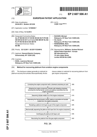
for recovering platinum group elements from an article
containing at least one platinum group element, including
for example new and improved methods for recovering
platinum from engine turbine blades.
SUMMARY
[0006] Aspects of the present disclosure provide for
the recovery of platinum from gas turbine engine com-
ponents that are being discarded or in conjunction with
the removal of platinum-containing coatings therefrom
during repair and reworking.
[0007] One aspect of the present disclosure is a meth-
od for recovering platinum from an gas engine compo-
nent, comprising: contacting the engine component with
a chemical comprising an acid; stripping the engine com-
ponent, wherein said stripping comprises removing the
thermal barrier control and platinum aluminide from the
engine component; dissolving soluble metals out of the
engine component; separating the thermal barrier con-
trol, platinum aluminide and soluble metals from the en-
gine component; revealing a platinum-rich layer as part
of the engine component; mechanically separating the
platinum-rich layer from the engine component; centri-
fuging the platinum-rich layer; and recovering the plati-
num from the gas engine component.
[0008] In another aspect, the present disclosure is a
method for recovering platinum from a gas engine com-
ponent, comprising: contacting the engine component
with a chemical comprising an acid; dissolving at least a
portion of a thermal barrier coating and platinum alumi-
nide on said engine component to expose a platinum rich
layer; separating the platinum-containing layer from the
thermal barrier coating and platinum aluminide; mechan-
ically removing the platinum-containing layer from the
engine component; and recovering the platinum from the
platinum-containing layer by centrifugation.
[0009] In one embodiment, the gas engine component
is a turbine blade. The separating the platinum-rich layer
step or mechanicallyremovingstep can beaccomplished
by high ultrasonic treatment of the component, tumbling
of the component, vibratory finishing of the component,
dry iceblastingof the component, or a combination there-
of. In one example, the separating the platinum-rich layer
step or mechanically removing step is selected from the
group consisting of hand brushing, high pressure water
blasting, ultrasonic cleaning, tumbling, vibratory finish-
ing, or a combination thereof. In another embodiment,
the component is first treated in a ultrasonic bath and
subsequently the component undergoes a tumbling step,
vibratory finishing, or a combination thereof. This se-
quential approach can effectively remove any residual
platinum.
[0010] In one embodiment, the separating the plati-
num-rich layer step or mechanically removing step is ac-
complished by high ultrasonic treatment of the compo-
nent for a period of at least 3 hours. In another embodi-
ment, the separating the platinum-rich layer step or me-
chanically removing step is accomplished by treatment
of the component in an ultrasonic environment, and
wherein the platinum-rich layer is dislodged from the
component and a slurry is formed comprising the plati-
num-rich residue in water.
[0011] In one embodiment, the separating the plati-
num-rich layer step or mechanically removing step is ac-
complished by tumbling treatment of the component for
a period of at least 45 minutes. In another embodiment,
the separating the platinum-rich layer step or mechani-
cally removing step is accomplished by treatment of the
component in a tumbling environment, and wherein the
platinum-rich layer is dislodged from the component and
a slurry is formed comprising the platinum-rich residue
in water.
[0012] In one aspect, the present disclosure is a meth-
1 2](data:image/gif;base64,R0lGODlhAQABAIAAAAAAAP///yH5BAEAAAAALAAAAAABAAEAAAIBRAA7)
Recommandé
Contenu connexe
Similaire à Ep2607506 a1
Similaire à Ep2607506 a1 (20)
Plus de Mark Rosenzweig
Dernier
Dernier (20)
Ep2607506 a1
- 1. Printed by Jouve, 75001 PARIS (FR) (19)EP2607506A1 TEPZZ 6Z75Z6A_T (11) EP 2 607 506 A1 (12) EUROPEAN PATENT APPLICATION (43) Date of publication: 26.06.2013 Bulletin 2013/26 (21) Application number: 12196949.7 (22) Date of filing: 13.12.2012 (51) Int Cl.: C22B 11/02 (2006.01) (84) Designated Contracting States: AL AT BE BG CH CY CZ DE DK EE ES FI FR GB GR HR HU IE IS IT LI LT LU LV MC MK MT NL NO PL PT RO RS SE SI SK SM TR Designated Extension States: BA ME (30) Priority: 22.12.2011 US 201113334810 (71) Applicant: General Electric Company Schenectady, NY 12345 (US) (72) Inventors: • KOOL, Lawrence Bernard Niskayuna, NY New York 12309 (US) • RUCKER, Michael Niskayuna, NY New York 12309 (US) • HU, Genfa Niskayuna, NY New York 12309 (US) • ROSENZWEIG, Mark Niskayuna, NY New York 12309 (US) (74) Representative: Williams, Andrew Richard Global Patent Operation - Europe GE International Inc 15 John Adam Street London WC2N 6LU (GB) (54) Method for recovering platinum from aviation engine components (57) The disclosure relates generally to methods for platinum recoveryfrom articles.Morespecifically, thedis- closure relates to methods for recovering platinum from gas engine components.
- 2. EP 2 607 506 A1 2 5 10 15 20 25 30 35 40 45 50 55 Description BACKGROUND [0001] Thisinventionrelatestoamethodfor recovering platinum group elements from an article containing at least one platinum group element. [0002] Modem gas or combustionturbinesmust satisfy the highest demands with respect to reliability, weight, power, economy, and operating service life. In the devel- opment of such turbines, the material selection, the search for new suitable materials, as well as the search for new production methods, among other things, play an important role in meeting standards and satisfying the demand. [0003] The platinum group metals (PGM) or PGMs (platinum, palladium, rhodium, iridium, osmium, and ru- thenium) are becoming increasingly important to the glo- bal economy. The aviation industry uses precious metals in the manufacture of aircraft engines. Gold and silver, as well as palladium and platinum, are used in the man- ufacture of different types of aircraft engines. Typically, an aircraft engine has up to 23 parts that contain precious metals. Various aircraft engine parts that use precious metals include vanes, stators, blades, fuel nozzles, fuel manifolds, tobi ducts, and heat exchangers. Whereas parts of an aircraft’s engine turbine system and avionics system use gold and silver, the aircraft blades use plat- inum. This invention relates to the recovery of platinum from used aviation components. [0004] After the life of an aircraft engine is over, the aviation industry can still recover precious metal from aircraft engines and their parts. Until recently, platinum group metals (PGM) were recovered by classical precip- itation procedures, which involved many repeated pre- cipitation/redissolution stages in order to obtain metal of the desired purity. These processes are extremely tedi- ous and time-consuming, with metal being tied-up in process often for many months. [0005] Yet, recovery of precious metals can account for up to 50percent of an aircraft engine’s recycling value. As such, there is a need for new and improved methods for recovering platinum group elements from an article containing at least one platinum group element, including for example new and improved methods for recovering platinum from engine turbine blades. SUMMARY [0006] Aspects of the present disclosure provide for the recovery of platinum from gas turbine engine com- ponents that are being discarded or in conjunction with the removal of platinum-containing coatings therefrom during repair and reworking. [0007] One aspect of the present disclosure is a meth- od for recovering platinum from an gas engine compo- nent, comprising: contacting the engine component with a chemical comprising an acid; stripping the engine com- ponent, wherein said stripping comprises removing the thermal barrier control and platinum aluminide from the engine component; dissolving soluble metals out of the engine component; separating the thermal barrier con- trol, platinum aluminide and soluble metals from the en- gine component; revealing a platinum-rich layer as part of the engine component; mechanically separating the platinum-rich layer from the engine component; centri- fuging the platinum-rich layer; and recovering the plati- num from the gas engine component. [0008] In another aspect, the present disclosure is a method for recovering platinum from a gas engine com- ponent, comprising: contacting the engine component with a chemical comprising an acid; dissolving at least a portion of a thermal barrier coating and platinum alumi- nide on said engine component to expose a platinum rich layer; separating the platinum-containing layer from the thermal barrier coating and platinum aluminide; mechan- ically removing the platinum-containing layer from the engine component; and recovering the platinum from the platinum-containing layer by centrifugation. [0009] In one embodiment, the gas engine component is a turbine blade. The separating the platinum-rich layer step or mechanicallyremovingstep can beaccomplished by high ultrasonic treatment of the component, tumbling of the component, vibratory finishing of the component, dry iceblastingof the component, or a combination there- of. In one example, the separating the platinum-rich layer step or mechanically removing step is selected from the group consisting of hand brushing, high pressure water blasting, ultrasonic cleaning, tumbling, vibratory finish- ing, or a combination thereof. In another embodiment, the component is first treated in a ultrasonic bath and subsequently the component undergoes a tumbling step, vibratory finishing, or a combination thereof. This se- quential approach can effectively remove any residual platinum. [0010] In one embodiment, the separating the plati- num-rich layer step or mechanically removing step is ac- complished by high ultrasonic treatment of the compo- nent for a period of at least 3 hours. In another embodi- ment, the separating the platinum-rich layer step or me- chanically removing step is accomplished by treatment of the component in an ultrasonic environment, and wherein the platinum-rich layer is dislodged from the component and a slurry is formed comprising the plati- num-rich residue in water. [0011] In one embodiment, the separating the plati- num-rich layer step or mechanically removing step is ac- complished by tumbling treatment of the component for a period of at least 45 minutes. In another embodiment, the separating the platinum-rich layer step or mechani- cally removing step is accomplished by treatment of the component in a tumbling environment, and wherein the platinum-rich layer is dislodged from the component and a slurry is formed comprising the platinum-rich residue in water. [0012] In one aspect, the present disclosure is a meth- 1 2
- 3. EP 2 607 506 A1 3 5 10 15 20 25 30 35 40 45 50 55 od for recovering platinum from a turbine blade, compris- ing: dipping the turbine blade into a chemical comprising an acid; dissolving at least 50% of a thermal barrier coat- ing or platinum aluminide on said turbine blade; exposing a platinum rich layer on said turbine blade; mechanically separating the platinum-rich layer from the turbine blade; and recovering the platinum from the platinum-rich layer by centrifugation. [0013] These and other aspects, features, and advan- tages of this disclosure will become apparent from the following detailed description of the various aspects of the disclosure taken in conjunction with the accompany- ing drawings. BRIEF DESCRIPTION OF THE FIGURES [0014] The subject matter, which is regarded as the invention, isparticularlypointedout and distinctlyclaimed in the claims at the conclusion of the specification. The foregoing and other features and advantages of the dis- closure will be readily understood from the following de- tailed description of aspects of the invention taken in con- junction with the accompanying drawings. Figure 1 shows a table, indicating the amount of plat- inum-rich smut removed from a turbine blade stripped using GRC chemistry. Figure 2 shows a graphic of one aspect of the plat- inum recovery process. Figure 3a and 3b recite the steps for recovering plat- inum from an gas engine component, and Figure 3c recites the steps for recovering platinum from a tur- bine blade. DETAILED DESCRIPTION [0015] In an aircraft gas turbine (jet) engine, air is drawn into the front of the engine, compressed by a shaft-mounted compressor, and mixed with fuel. The mixture is combusted, and the resulting hot combustion gasesarepassedthroughaturbinemountedon thesame shaft. The flow of gas turns the turbine by contacting an airfoil portion of the turbine blade, which turns the shaft and provides power to the compressor. The hot exhaust gases flow from the back of the engine, driving it and the aircraft forwardly. [0016] During operation of gas turbine engines, the temperatures of combustion gases may exceed 3,000° F, considerably higher than the melting temperatures of the metal parts of the engine, which are in contact with these gases. The metal parts that are particularly subject to high temperatures, and thus require particular atten- tion with respect to cooling, are the hot section compo- nents exposed to the combustion gases, such as blades and vanes used to direct the flow of the hot gases, as well as other components such as shrouds and combus- tors. [0017] The hotter the turbine gases, the more efficient is the operation of the jet engine. There is thus an incen- tive to raise the turbine operating temperature. However, the maximum temperature of the turbine gases is nor- mally limited by the materialsused to fabricatetheturbine vanes and turbine blades of the turbine. Many approach- es have beenusedto increase the operating temperature limits and operating lives of the airfoils of the turbine blades and vanes. [0018] The metal temperatures can be maintained be- low melting levels with current cooling techniques by us- ing a combination of improved cooling designs and ther- mal barrier coatings. In one approach, a protective layer is applied to the airfoil of the turbine blade or turbine vane component, which acts as a substrate. Among the cur- rently known diffusional protective layers are aluminide and platinum aluminide layers. The protective layer pro- tects the substrate against environmental damage from the hot, highly corrosive combustion gases. This protec- tive layer, with no overlying ceramic layer, is useful in intermediate-temperature applications. For higher tem- perature applications, a ceramic thermal barrier coating layer may be applied overlying the protective layer, to form a thermal barrier coating (TBC) system. [0019] Thermal barrier coatings (TBCs) are well-known ceramic coatings, for example, yttrium stabi- lized zirconia. Ceramic thermal barrier coatings usually do not adhere optimally directly to the superalloys used in the substrates. Therefore, an additional metallic layer called a bond coat is placed for example, by chemical vapor deposition (CVD), between the substrate and the TBC to improve adhesion of the TBC to the underlying component. In one form, the bond coat is made of a dif- fusionnickel aluminide or platinum aluminide, whosesur- face oxidizes to form a protective aluminum oxide scale in addition to improving adherence of the ceramic TBC. [0020] Even with the use of these protective tech- niques, there remain problems to overcome in extending the operating service temperatures and operating lives of the turbine blade components. There is a large cost to replacing these turbine blade components, especially because of the expensive components used to manufac- ture such components. As a result, it is beneficial to ex- tract particular needed components from used parts for future use in the manufacture of new parts. For example, platinum group metals (PGM) are often employed in the aviation industry. Because platinum group metals are rel- atively expensive and are often obtained from sources outside the United States, it is advantageous to recover platinum group metals from parts used in airplanes. [0021] Many advanced gas turbine engine compo- nents, especiallyturbineblades, arecoatedwithplatinum modified diffusion aluminide coatings (PtAl). These coat- ings offer superior environmental protection in oxidation and Type I hot corrosion conditions within a turbine en- gine. As outlined above, these coatings are also em- ployed as bond coatings beneath physically vapor de- 3 4
- 4. EP 2 607 506 A1 4 5 10 15 20 25 30 35 40 45 50 55 posited (PVD) thermal barrier coatings. [0022] The Pt present in PtAl coatings is most often deposited by electroplating. To develop the required PtAl chemistry and structure, about 0.5-0.8 grams of Pt are electroplated onto relatively smaller turbine blades, while up to on the order of 1.5 grams of Pt may be electroplated onto larger blades. After plating, the Pt is incorporated into the coating by diffusion, with the final composition of the predominant coating phase being (Ni,Pt)Al. [0023] A PtAl coating may be removed from a blade if the coating itself or some other feature of the blade does not meet the engineering or quality requirements for the part. In such a case, the coating is stripped, the part re- worked and then recoated with PtAl. Turbine blades are also stripped of PtAl coatings after engine operation to enable inspection and repair of the turbine blades. [0024] Stripping of PtAl coatings is accomplished in a variety of manners. Stripping of PtAl coatings can be ac- complished by acid stripping using mineral acids such as hydrochloric, phosphoric, nitric, and mixtures of these acids. Theacids react withthecoating and dissolve some of the coating constituents, especially Ni. After the reac- tion, a thin, loosely adherent, black film residue compris- ing Pt, aluminum oxides and heavy metal oxides of var- ious elements from the substrate material is left behind on the blade. After stripping a number of parts, the strip- ping solutions become ineffective and are discarded. Most often the acids are neutralized, the metals chemi- cally precipitated out, and the precipitate filtered from the solution. The precipitate, although it contains minor amounts of Pt, is disposed of as solid waste. [0025] The platinum rich residue was removed from stripped turbine blades by mechanical methods such as ultrasonic treatment or vibratory finishing. Traditionally a "cutting" type media has been used in vibratory finishing machines to remove residue. Cutting media consist of abrasive aluminum oxide particles in a soft binder. The binder breaks down, releasing aluminum oxide particles intothevibratoryfinishmachine.Large volumesof sludge are produced. The residue is thus contaminated and di- luted by the abrasive media as it breaks down, such that the Pt is no longer economically recoverable. Overflow from wet blast or vibratory finishing machines used to clean blades is treated in a wastewater system, and the solids, although they contain Pt, are disposed of as waste. [0026] One aspect of the present disclosure is a meth- od for recovering platinum from a gas engine component, comprising: contacting the engine component with a chemical comprising an acid; stripping the engine com- ponent, wherein said stripping comprises removing the thermal barrier control and platinum aluminide from the engine component; dissolving soluble metals out of the engine component; separating the thermal barrier con- trol, platinum aluminide and soluble metals from the en- gine component; revealing a platinum-rich layer as part of the engine component; mechanically separating the platinum-rich layer from the engine component; centri- fuging the platinum-rich layer; and recovering the plati- num from the gas engine component. [0027] The gas engine component can be a turbine blade. The separating the platinum-rich layer step or me- chanically removing step can be accomplished by high ultrasonic treatment of the component, tumbling of the component, vibratory finishing of the component, dry ice blasting of the component, or a combination thereof. In one example, the separating the platinum-rich layer step or mechanically removing step is selected from the group consisting of hand brushing, high pressure water blast- ing, ultrasonic cleaning, tumbling, vibratory finishing, or a combination thereof. In another embodiment, the com- ponent is first treated in a ultrasonic bath and subse- quently the component undergoes a tumbling step, vi- bratory finishing, or a combination thereof. This sequen- tial approach can effectively remove any residual plati- num. [0028] The high ultrasonic treatment of the component can be for a period of at least 3 hours. Inoneembodiment, the ultrasonic treatment of the component is for a period of between 3 hours to 8 hours. In another embodiment, the ultrasonic treatment of the component is for about 12 hours. In another embodiment, the separating the plati- num-rich layer step or mechanically removing step is ac- complished by treatment of the component in an ultra- sonic environment, and wherein the platinum-rich layer is dislodged from the component and a slurry is formed comprising the platinum-rich residue in water. [0029] The tumbling treatment of the component can be for a period of at least 45 minutes. In one embodiment, the tumbling treatment isfor a period between 30 minutes and 300 minutes. In one embodiment, the tumbling treat- ment isfor a periodbetween60 minutesand180minutes. In another embodiment, the tumbling treatment is for about 120 minutes. In one embodiment, the separating the platinum-rich layer step or mechanically removing step is accomplished by treatment of the component in a tumbling environment, and wherein the platinum-rich layer is dislodged from the component and a slurry is formed comprising the platinum-rich residue in water. [0030] A PtAl coating may be removed from a blade if the coating itself or some other feature of the blade does not meet the engineering or quality requirements for the part. In such a case, the coating is stripped, the part re- worked and then recoated with PtAl. Turbine blades are also routinely stripped of PtAl coatings after engine op- eration to enable inspection and repair of the turbine blades. [0031] In situations where PtAl coatings are removed mechanically by abrasive grit blasting, rather than chem- ically, Pt-bearing debris from grit blasting is filtered from the process air and is disposed of as solid waste. By one of the above processes, the Pt from the PtAl stripping operation finds its way into the final waste stream of a turbine blade repair plant. Many high volume operations feed into the final waste stream in a manufacturing plant and dilute the concentration of Pt in the solid waste to 5 6
- 5. EP 2 607 506 A1 5 5 10 15 20 25 30 35 40 45 50 55 the point where it is not economically viable to recover the precious metal. [0032] In certain embodiments, the PtAl bondcoat is removed from the turbine blade by means of a chemical stripping process. This process dissolves aluminum and other metals from the PtAl coating, leaving behind a plat- inum-rich smut. In one embodiment, the disclosure de- scribes a new and improved method for mechanically removing this smut, including ultrasonics, vibrations, and dry-ice blasting, and recovering the smut quantitatively by means of centrifugation. The presently disclosed method is also applicable to end-of-life parts. [0033] In one aspect, the present disclosure is a meth- od for recovering platinum from a gas engine component, comprising: contacting the engine component with a chemical comprising an acid; dissolving at least a portion of a thermal barrier coating and platinum aluminide on said engine component to expose a platinum rich layer; separating the platinum-containing layer from the ther- mal barrier coating and platinum aluminide; mechanically removing the platinum-containing layer from the engine component; and recovering the platinum from the plati- num-containing layer by centrifugation. [0034] In one embodiment, different chemicals are used for leaching aluminum. In another embodiment, dif- ferent methods are used for mechanically removing the smut and/or recovering the fine powdered platinum-rich smut. Prior to the teachings of the present disclosure, removal of the platinum-rich smut was carried out by means of aluminum oxide grit blasting to provide a clean airfoil surface. In this process the platinum was incorpo- rated into the spent grit blasting material and significantly diluted. This spent grit was then classified as hazardous waste and had to be disposed of accordingly at great expense. [0035] Applicants have identified a chemical stripping process to leach out the soluble metals (primarily alumi- num) while leaving behind a platinum-rich "smut." Fur- ther, Applicants’ disclosure teaches a new and improved method by which this platinum-rich smut can be removed without contamination of the smut by foreign materials. In one embodiment, a vibratory tumbler with ceramic me- dia and water results in complete, satisfactory removal of the smut and the formation of a fine suspension of platinum smut in water. This water is then introduced into a continuous high speed centrifuge (CEPA) which sep- arates the smut from the water to provide a product that is >45 wt% platinum. In one embodiment, the disclosed process allows for the recovery of the platinum from the coatings quantitatively. [0036] Prior attempts to recover platinum have in- volved dissolving the platinum in very strong acids, then neutralizing the acid to precipitate platinum salts, which were highly contaminated; this process is not particularly viable for commercial use. In contrast, in one aspect, the present disclosure is a method for recovering platinum from a turbine blade, comprising: dipping the turbine blade into a chemical comprising an acid; dissolving at least 50% of a thermal barrier coating or platinum alumi- nide on said turbine blade; exposing a platinum rich layer on said turbine blade; mechanically separating the plat- inum-rich layer from the turbine blade; and recovering the platinum from the platinum-rich layer by centrifuga- tion. U.S. Patent Numbers 6,494,960, 5,976,265, and 5,486,135 and application numbers 2003/005020, 2002/010309, and 2002/0072306 provide additional al- ternatives and are incorporated herein. [0037] In one embodiment, the disclosure is directed to mechanical removal of platinum-rich smut from airfoils that havebeentreatedusingchemical stripping methods. Applicants teach that these mechanical methods include an ultrasonic bath, tumbling with media, vibratory finish- ing, water jets, brushes, compressed air, dry-ice blasting and the like. In another embodiment, the present disclo- sure is directed to recovery of the fine platinum power by filtration, centrifugation, settling, decanting, or a combi- nation thereof. [0038] The advantages of the present disclosure in- clude the reduced loss of valuable platinum metal and the avoidance of the cost of disposal of used grit blasting media that is contaminated with platinum and other met- als. Inaddition, in order topracticethe present disclosure, in one embodiment, conventional chemical stripping processes already in place and approved by the FAA can be used. Moreover, as mentioned supra, by practicing the presently disclosed method, the cost of disposal of spent grit blast media as hazardous waste is avoided and valuable platinum metal is recovered and can be recy- cled. [0039] Grit blasting is a common method to clean dirt and remove coatings. Unfortunately, grit blasting does not clean dirty or blocked internal passageways. Grit blasting can damage the base alloy thereby thinning air- foil walls. Chemical solutions are used for cleaning dirt and stripping coatings from gas turbine components. [0040] A first class of stripping compositions (compo- sition (i)) comprises aliphatic or aromatic sulfonic acids. Examples of suitable aliphatic sulfonic acids are meth- anesulfonic acid (MSA) and ethanesulfonic acid, with methanesulfonic acid being preferred. Illustrative aro- matic sulfonic acids are benzene sulfonic acid, toluene sulfonic acid, and naphthalene sulfonic acid. In a partic- ular embodiment, stripping of the turbine blade is per- formed by using a composition comprising an aliphatic sulfonic acid such as MSA, ethanesulfonic acid, meth- anesulfonic acid, or a combination thereof. [0041] A second class of stripping compositions (i.e., composition (ii)) includes a solution of an inorganic acid and an organic solvent. Examples of the inorganic acid for this class of compositions are hydrochloric acid, nitric acid, and perchloric acid. [0042] In certain embodiments, the solvent is one which reduces the activity and increases the wetting ca- pability of theinorganicacidrelative tothesubstrate. (The chemical interaction between an acid and a hydrocarbon solvent will often differ from the interaction between the 7 8
- 6. EP 2 607 506 A1 6 5 10 15 20 25 30 35 40 45 50 55 acid and a solvent like water). It has been found that the combination of the inorganic acid and the organic solvent removes substantially all of the aluminide coating mate- rial without adversely affecting the substrate. [0043] Examples of organic solvents for use in combi- nation with the inorganic acid include aliphatic alcohols, aromatic alcohols, chlorinated alcohols, ketones, ni- trile-based solvents, nitrated hydrocarbon solvents, ni- trated aromatic solvents such as nitrobenzene; chlorin- ated hydrocarbons, amines, and mixtures of any of the foregoing. Several specific examples of the aliphatic al- cohols are methanol, ethanol, and isopropanol. Mixtures of alcohols may be used as well. Specific examples of the aromatic alcohols are phenols and substituted phe- nols. [0044] A third stripping composition for this invention (composition (iii)) comprises sulfuric acid or an aqueous solution of sulfuric acid. For the aqueous solution, the ratio of acid to water is usually in the range of about 10:90 to about 65:35. In certain embodiments, the ratio is in the range of about 15:85 to about 40:0. Moreover, a wetting agent is usually used in this type of stripping composition, as described below. [0045] For end use applications in which minimal pit- ting of the substrate if any is preferred, a different strip- pingcompositioncouldbeemployed. Forexample, meth- anesulfonic acid is effective at removing aluminide ma- terial from the substrate, although the rate of removal is not as high as in the case of HCl-alcohol. A distinct ad- vantage of methanesulfonic acid is that it does not ad- versely affect the substrate to any substantial degree, beyond uniform corrosion. As used herein, "uniform cor- rosion" refers to the removal of a thin layer of the sub- strate - usually less than about 2 microns in thickness. [0046] In some embodiments, the stripping composi- tion further includes a wetting agent. The wetting agent reduces the surface tension of the composition, permit- ting better contact with the substrate and the alumi- nide-based coating. Illustrative wetting agents are poly- alkylene glycols, glycerol, fatty acids, soaps, emulsifiers, and surfactants. The wetting agent is usually present at a level in the range of about 0.1% by weight to about 5% by weight, based on the total weight of the composition. [0047] Other additives are sometimes used in the strip- ping composition. For example, inhibitors are sometimes employed to lower the proton concentration, and thereby lower the activity of the acid in the composition. The low- ered activity in turn decreases the potential for pitting of the substrate surface. An exemplary inhibitor is a solution of sodium sulfate in sulfuric acid, or a solution of sodium chloride in hydrochloric acid. The level of inhibitor used is usually about 1 % by weight to about 15% by weight, based on the weight of the entire stripping composition. Moreover, oxidizing agents are sometimes used in the stripping composition to prevent the formation of a re- ducing environment. Examples include peroxides (e.g., hydrogen peroxide), chlorates, perchlorates, nitrates, permanganates, chromates, and osmates (e.g., osmium tetroxide). The level of oxidizing agent used is usually about 0.01% by weight to about 5% by weight, based on the weight of the entire stripping composition. In one em- bodiment, the oxidizing agent is used with acids that are reducing agents, e.g. hydrochloric acid. [0048] The particular stripping composition may be ap- plied to the substrate in a variety of ways. For example, it can be brushed or sprayed onto the surface. Very often, immersion of the substrate in a bath of the stripping com- position is the most practical technique. The bath can be maintained at a temperature below about 170° F. (77° C.) whilethesubstrate is immersed therein. Ina particular embodiment, the bath is maintained at a temperature be- low about 130° F. (54° C.). The process could be carried out at room temperature, although a higher temperature range would usually be maintained to ensure process consistency if the room temperature is variable. Higher temperatures (within the boundaries set forth above) sometimes result in more rapid removal of the aluminide coating. [0049] Thebathscontainingthe strippingcompositions are often stirred or otherwise agitated while the process is carried out, to permit maximum contact between the stripping agent and the coating being removed. A variety of known techniques could be used for this purpose, such as the use of impellers, ultrasonic agitation, magnetic agitation, gas bubbling, or circulation-pumping. Immer- sion time in the bath will vary, based on many of the factors discussed above. On a commercial scale, the im- mersion time will usually range from about 15 minutes to about 400 minutes. In some embodiments, the immer- sion time will be a period less than about 150 minutes. In particular embodiments, the immersion time will be a period less than about 75 minutes. Exposure to the strip- ping composition causes the aluminide coating on the surface of the substrate to become degraded. [0050] In some embodiments of the present disclo- sure, the substrate surfaceiscontacted with twostripping compositions, in sequence. The first composition is one which very quickly begins to remove the aluminide ma- terials. A specific example is the mixture of the inorganic acid and the solvent which reduces the activity of the inorganic acid relative to the substrate, as described pre- viously. Illustrative compositions of this type are hydro- chloric acid with an alcohol such as ethanol; and sulfuric acid with water. [0051] The second stripping composition is one which is capable of removing the aluminide material more slow- ly, and with no pitting or attack on the substrate, except for the possible occurrence of uniform corrosion, as dis- cussed previously. One example is the stripping compo- sition based on an alkane sulfonic acid, such as meth- anesulfonic acid. [0052] Typically, each stripping composition is used in the form of a bath in which the substrate can be im- mersed. Contact times and bath temperatures will vary, based on many of the factors described previously, e.g., type and amount of aluminide material requiring removal. 9 10
- 7. EP 2 607 506 A1 7 5 10 15 20 25 30 35 40 45 50 55 Usually, the first bath will be maintained at a temperature in the range of about 0° C. to about 40° C., with an im- mersion time betweenabout 5 minutes andabout 30 min- utes. The second bath will typically be maintained at a temperature in the range of about 40° C. to about 60° C., with an immersion time between about 30 minutes and about 300 minutes. As in previous embodiments, the sur- face can then be subjected to a gentle abrasion step (or similar technique) to remove the degraded coating, e.g., by light grit-blasting. [0053] The present disclosure relates generally to plat- inum recovery and methods for recovering platinum from aviation components, including engine turbine blades. EXAMPLES [0054] The disclosure, having been generally de- scribed, may be more readily understood by reference to the following examples, which are included merely for purposes of illustration of certain aspects and embodi- ments of the present disclosure, and are not intended to limit the disclosure in any way. [0055] Figure 1 is a table, showing platinum-rich smut removed from a turbine blade stripped using GRC chem- istry. The CFM56-7 blade was stripped using GRC chem- istry, the smut was removed in an ultrasonic bath, and filtered through Whatman #4 fluted filter. The isolated yield was 1.5g. [0056] Figure 2 shows a graphic of one aspect of the platinum recovery process. [0057] As shown in Figure 3a, the method for recover- ing platinum from an gas engine component, comprises contacting the engine component with a chemical com- prising an acid (305). The engine component is stripped, removing the thermal barrier control and platinum alumi- nide from the component (310). Having dissolved the sol- uble metals out of the engine component (315), the ther- mal barrier control, platinum aluminide and soluble met- als are separated from the engine component (320), re- vealing a platinum-rich layer as part of the engine com- ponent (325). The platinum-rich layer is then mechani- cally separated from the engine component (330), cen- trifuged (335) and the platinum is recovered from the en- gine component (340). [0058] In another example, shown in Figure 3b, the method for recovering platinum from a gas engine com- ponent,comprises contacting theenginecomponent with a chemical comprising an acid (350). At least a portion of a thermal barrier coating and platinum aluminide that is on said engine component is dissolved to expose a platinum rich layer (355). This platinum-rich layer is sep- arated from the thermal barrier coating and platinum alu- minide (360). Having mechanically removed the plati- num-rich layer from the engine component (365), the platinum is recovered from the platinum-rich layer by spinning down the slurry (370). [0059] In another embodiment, shown in Figure 3c, the method for recoveringplatinum from a turbine bladecom- prises dipping the turbine blade into a chemical compris- ing an acid (375), and dissolving at least 50% of a thermal barrier coatingor platinum aluminidethat is ontheturbine blade (380). Once the platinum-rich layer is exposed on the turbine blade (385), it is then mechanically separated from the turbine blade (390), and the platinum-rich layer is recovered by centrifuging the slurry containing the plat- inum-rich layer (395). [0060] In a first example, lab-scale experiments were conducted to determine whether platinum could be re- covered in the form of "smut" that remains on stripped blades after PtAI-coated airfoils have been run through the chemical stripping process. Applicants conceived that platinum can be recoverable after this stripping step because the stripping chemicals function by dissolving aluminum from the PtAI, leaving behind a loosely-adher- ent platinum "smut." [0061] Individual blades were stripped in thelaboratory using two different stripping chemistries, one of which being using the MSA. The stripped blades were then des- mutted in a lab-scale ultrasonic bath and the resultant suspension was filtered via gravity through filter paper. A CFM56-7 stage 1 blade afforded 1.5 g of recovered material that was submitted for ICP analysis. CFM56-7 blades were used because they are representative of a type of blade that has PtAl coating and are commonly repaired. The results of this analysis are shown in Figure 1 and indicate that the smut consisted of 47-49% plati- num. [0062] A 5 g sample of this material was analyzed and found that the material contained ">40%" platinum, far exceeding the 25% limit for customers’ favorable processing costs. [0063] A full-scale study on a set of 24 blades was con- ducted. The turbine blades were stripped using the con- ventional MSA stripping bath. Subsequently, two differ- ent methods of platinum rich smut removal were per- formed in place of grit blasting: an ultrasonic bath and tumbling (see Figure 2). [0064] Although it appears that tumbling or vibratory finishing provide more complete removal of smut, the method suffers from the drawback that the recovered smut is contaminated (>80%) with ceramic particulate caused by abrasion of the ceramic tumbling media. The smut recovered from the ultrasonic desmutting operation was uncontaminated by tumbling media. [0065] Thus, not all methods for desmutting the turbine blades provide similar results. Applicants have discov- ered, inpart, that there isanadvantagetousingultrasonic desmutting as compared to other removal methods. Fur- ther, Applicants discovered that more vigorous ultrasonic desmutting provides for better platinum recovery and in a shorter period of time. A variety of methods for smut removal are available. Ultrasonic bath, tumbling and vi- bratory finishing all can be used, either alone or in com- bination. If tumbling or vibratory finishing are used, the resultant product can be contaminated with ceramic me- dia material that is abraded away during the process. 11 12
- 8. EP 2 607 506 A1 8 5 10 15 20 25 30 35 40 45 50 55 The method selected is dependent upon the purity re- quirements of the subsequent purification steps. Ultra- sonic baths typically produce the purest product, but some residual platinum may adhere to the airfoils. This residual platinum can be effectively removed in a subse- quent tumbling or vibratory finishing step. [0066] In a second experiment, modifications to the configuration of the ultrasonic bath were made to en- hance smut removal. This resulted in ca. 80% removal of smut (based upon visual estimation). The ultrasonic bath used for Pt smut removal was one of a variety of commercially-available ultrasonic baths using a varying, sweeping frequency. Higher ultrasonic bath energy and a higher bath volume to part surface area ratio results in shorter cycle times; lower bath energy with a lower bath volume to part surface area ratio requires longer cycle times. Desmutting cycles can range from a few minutes to 45 minutes, depending on bath volume, number of parts and ultrasonic energy. The resultant suspension wasfilteredviagravityusinga fluted Whatmanfilter paper of medium porosity. Higher porosity (faster) results in shorter cycle and lower yield, while lower porosity (slow- er) results in higher yield and longer cycle time. [0067] Closer examination of the filtration recovery method revealed that the smut became embedded in the bag, making ultimate recovery challenging. As a result, Applicants identified alternative methods to recover fine particulates dispersed in a relatively large volume of liq- uid. Applicants identified a method that provides smut free of contamination. This method employs the CEPA highspeed continuous centrifuge, providing quantitative recovery of platinum smut that is ca. 50% platinum by weight. [0068] Applicants also considered alternatives to ultra- sonic desmutting followed by continuous centrifuging. In one embodiment, Applicants identified dry-ice blasting as an alternative. Dry-ice blasting is a process whereby dry-ice (solid carbon dioxide) is ejected at high velocity from a nozzle and used to remove the smut from the blades. A wide range of velocities, particle sizes and par- ticle velocities may be used. In general, a higher energy particle can more effectively remove smut, but at higher cost. The advantage of this method is that it might be possibleto combine the smut removal and recovery proc- esses. Thismethod mayrequire thedesignandconstruc- tion of a dry-ice blasting booth that would be connected to a dust collector that would trap the smut that was re- moved. Applicants have established that either method of recovery (ultrasonic desmutting followed by continu- ous centrifugation or dry-ice blasting with dust collection) would efficiently remove platinum smut. [0069] The advantages of the presently taught disclo- sure is that it provides for improved methods for recov- ering the value of the recovered platinum, 0.5 - 1.5 g Pt/ blade (depending on engine). Platinum spot price is ap- proximately $1600/oz; value per blade is therefore about $25 - $100. Since the present assignee produces tens of thousands of blades per, there is a significant value in the present discovery of new and improved processes for the recovery of platinum from used aviation parts, including engine turbine blades. [0070] It is to be understood that the above description is intended to be illustrative, and not restrictive. For ex- ample, the above-described embodiments (and/or as- pects thereof) may be used in combination with each other. In addition, many modifications may be made to adapt a particular situation or material to the teachings of the various embodiments without departing from their scope. While the dimensions and types of materials de- scribed herein are intended to define the parameters of the various embodiments, they are by no means limiting and are merely exemplary. Many other embodiments will be apparent to those of skill in the art upon reviewing the above description. The scope of the various embodi- ments should, therefore, be determined with reference to theappended claims, alongwith the full scope of equiv- alents to which such claims are entitled. In the appended claims, the terms "including" and "in which" are used as the plain-English equivalents of the respective terms "comprising" and "wherein." Moreover, in the following claims, the terms "first," "second," and "third," etc. are used merely as labels, and are not intended to impose numerical requirements on their objects. It is to be un- derstood that not necessarily all such objects or advan- tages described above may be achieved in accordance withanyparticularembodiment. Thus, for example,those skilled in the art will recognize that the systems and tech- niques described herein may be embodied or carried out in a manner that achieves or optimizes one advantage or group of advantages as taught herein without neces- sarily achieving other objects or advantages as may be taught or suggested herein. [0071] All publications, patents, and patent applica- tions mentioned herein are hereby incorporated by ref- erence in their entirety as if each individual publication or patent was specifically and individually indicated to be incorporated by reference. In case of conflict, the present application, including any definitions herein, will control. While the invention has been described in detail in con- nection with only a limited number of embodiments, it should be readily understood that the invention is not limited to such disclosed embodiments. Rather, the in- vention can be modified to incorporate any number of variations, alterations, substitutions or equivalent ar- rangementsnot heretoforedescribed, butwhicharecom- mensurate with the spirit and scope of the invention. Ad- ditionally, while various embodiments of the invention have been described, it is to be understood that aspects of the disclosure may include only some of the described embodiments. Accordingly, the invention is not to be seen as limited by the foregoing description, but is only limited by the scope of the appended claims. [0072] This written description uses examples to dis- close the invention, including the best mode, and also to enable any person skilled in the art to practice the inven- tion, including making and using any devices or systems 13 14
- 9. EP 2 607 506 A1 9 5 10 15 20 25 30 35 40 45 50 55 and performing any incorporated methods. The patent- able scope of the invention is defined by the claims, and may include other examples that occur to those skilled in the art. Such other examples are intended to be within the scope of the claims if they have structural elements that do not differ from the literal language of the claims, or if they include equivalent structural elements with in- substantial differences from the literal language of the claims. [0073] Various aspects and embodiments of the inven- tion are indicated in the following clauses: 1. A method for recovering platinum from an gas en- gine component, said method comprising: contacting the engine component with a chem- ical comprising an acid; stripping the engine component, wherein said stripping comprises removing the thermal barri- er control and platinum aluminide from the en- gine component; dissolving soluble metals out of the engine com- ponent; separating the thermal barrier control, platinum aluminide and soluble metals from the engine component; revealing a platinum-rich layer as part of the en- gine component; mechanically separating the platinum-rich layer from the engine component; centrifuging the platinum-rich layer; and recovering the platinum from the gas engine component. 2. The method of clause 1, wherein said gas engine component is a turbine blade. 3. The method of clause 1, wherein the separating the platinum-rich layer step is accomplished by high ultrasonic treatment of the component, tumbling of the component, dry ice blasting of the component, or a combination thereof. 4. The method of clause 1, wherein the separating the platinum-rich layer step is selected from the groupconsistingofhandbrushing, highpressurewa- ter blasting, ultrasonic cleaning, vibratory finishing, or a combination thereof. 5. The method of clause 1, wherein the separating the platinum-rich layer step is accomplished by high ultrasonic treatment of the component for a period of at least 3 hours. 6. The method of clause 1, wherein the separating the platinum-rich layer step is accomplished by treat- ment of the component in an ultrasonic environment, and wherein the platinum-rich layer is dislodged from the component and a slurry is formed comprising the platinum-rich residue. 7. The method of clause 1, wherein the separating the platinum-rich layer step is accomplished by tum- bling treatment of the component for a period of at least 45 minutes. 8. The method of clause 1, wherein the separating the platinum-rich layer step is accomplished by treat- ment of the component in a tumbling environment, and wherein the platinum-rich layer is dislodged from the component and a slurry is formed comprising the platinum-rich residue. 9. A method for recovering platinum from a gas en- gine component, said method comprising: contacting the engine component with a chem- ical comprising an acid; dissolving at least a portion of a thermal barrier coating and platinum aluminide on said engine component to expose a platinum rich layer; separating the platinum-containing layer from the thermal barrier coating and platinum alumi- nide; mechanically removing the platinum-containing layer from the engine component; and recovering the platinum from the platinum-con- taining layer by centrifugation. 10. The method of clause 9, wherein said gas engine component is a turbine blade. 11. The method of clause 9, wherein the mechani- cally removing step is accomplished by high ultra- sonic treatment of the component, tumbling of the component, dry ice blasting of the component, or a combination thereof. 12. The method of clause 9, wherein the mechani- cally removing step is selected from the group con- sisting of hand brushing, high pressure water blast- ing, ultrasonic cleaning, vibratory finishing, or a com- bination thereof. 13. The method of clause 9, wherein the mechani- 15 16
- 10. EP 2 607 506 A1 10 5 10 15 20 25 30 35 40 45 50 55 cally removing step is accomplished by high ultra- sonic treatment of the component for a period of at least 3 hours. 14. The method of clause 9, wherein the mechani- cally removing step is accomplished by treatment of the component in an ultrasonic environment, and wherein the platinum-rich layer is dislodged from the component and a slurry is formed comprising the platinum-rich residue in water. 15. The method of clause 9, wherein the mechani- cally removing step is accomplished by tumbling treatment of the component for a period of at least 45 minutes. 16. The method of clause 9, wherein the mechani- cally removing step is accomplished by treatment of the component in a tumbling environment, and wherein the platinum-rich layer is dislodged from the component and a slurry is formed comprising the platinum-rich residue in water. 17. A method for recovering platinum from a turbine blade, said method comprising: dipping the turbine blade into a chemical com- prising an acid; dissolving at least 50% of a thermal barrier coat- ing or platinum aluminide on said turbine blade; exposing a platinum rich layer on said turbine blade; mechanically separating the platinum-rich layer from the turbine blade; and recovering the platinum from the platinum-rich layer by centrifugation. 18. The method of clause 17, wherein said gas en- gine component is a turbine blade. 19. The method of clause 17, wherein the separating the platinum-rich layer step is accomplished by high ultrasonic treatment of the component, tumbling of the component, dry ice blasting of the component, or a combination thereof. 20. The method of clause 17, wherein the separating the platinum-rich layer step is selected from the groupconsistingofhandbrushing, highpressurewa- ter blasting, ultrasonic cleaning, vibratory finishing, or a combination thereof. 21. The method of clause 17, wherein the separating the platinum-rich layer step is accomplished by high ultrasonic treatment of the component for a period of at least 3 hours. 22. The method of clause 17, wherein the separating the platinum-rich layer step is accomplished by treat- ment of the component in an ultrasonic environment, and wherein the platinum-rich layer is dislodged from the component and a slurry is formed comprising the platinum-rich residue in water. 23. The method of clause 17, wherein the separating the platinum-rich layer step is accomplished by tum- bling treatment of the component for a period of at least 45 minutes. 24. The method of clause 17, wherein the separating the platinum-rich layer step is accomplished by treat- ment of the component in a tumbling environment, and wherein the platinum-rich layer is dislodged from the component and a slurry is formed comprising the platinum-rich residue in water. Claims 1. A method for recoveringplatinum from angas engine component, said method comprising: contacting the engine component with a chem- ical comprising an acid; stripping the engine component, wherein said stripping comprises removing a thermal barrier control and platinum aluminide from the engine component; dissolving soluble metals out of the engine com- ponent; separating the thermal barrier control, platinum aluminide and soluble metals from the engine component; revealing a platinum-rich layer as part of the en- gine component; mechanically separating the platinum-rich layer from the engine component; centrifuging the platinum-rich layer; and recovering the platinum from the gas engine component. 2. Themethodof claim1, wherein saidgasengine com- ponent is a turbine blade. 3. The method of either of claim 1 or 2, wherein the separating the platinum-rich layer step is accom- plished by high ultrasonic treatment of the compo- nent, tumbling of the component, dry ice blasting of the component, or a combination thereof. 4. The method of either of claim 1 or 2, wherein the separating the platinum-rich layer step is selected 17 18
- 11. EP 2 607 506 A1 11 5 10 15 20 25 30 35 40 45 50 55 from the group consisting of hand brushing, high pressure water blasting, ultrasonic cleaning, vibra- tory finishing, or a combination thereof. 5. Themethod of any preceding claim, wherein the sep- arating the platinum-rich layer step is accomplished by high ultrasonic treatment of the component for a period of at least 3 hours. 6. Themethod of any preceding claim, wherein the sep- arating the platinum-rich layer step is accomplished by treatment of the component in an ultrasonic en- vironment, and wherein the platinum-rich layer is dis- lodged from the component and a slurry is formed comprising the platinum-rich residue. 7. The method of either of claim 1 or 2, wherein the separating the platinum-rich layer step is accom- plished by tumbling treatment of the component for a period of at least 45 minutes. 8. The method of either of claim 1 or 2, wherein the separating the platinum-rich layer step is accom- plished by treatment of the component in a tumbling environment, and wherein the platinum-rich layer is dislodged from the component and a slurry is formed comprising the platinum-rich residue. 9. A method for recovering platinum from a gas engine component, said method comprising: contacting the engine component with a chem- ical comprising an acid; dissolving at least a portion of a thermal barrier coating and platinum aluminide on said engine component to expose a platinum rich layer; separating the platinum-containing layer from the thermal barrier coating and platinum alumi- nide; mechanically removing the platinum-containing layer from the engine component; and recovering the platinum from the platinum-con- taining layer by centrifugation. 10. Themethodof claim 9, whereinsaidgasenginecom- ponent is a turbine blade. 11. The method of either of claim 9 or 10, wherein the mechanicallyremoving step is accomplished by high ultrasonic treatment of the component, tumbling of the component, dry ice blasting of the component, or a combination thereof. 12. The method of either of claim 9 or 10, wherein the mechanically removing step is selected from the groupconsistingofhandbrushing, highpressurewa- ter blasting, ultrasonic cleaning, vibratory finishing, or a combination thereof. 13. The method of any of claims 9 to 12, wherein the mechanically removing step is accomplished by high ultrasonic treatment of the component for a period of at least 3 hours. 14. The method of any of claims 9 to 13, wherein the mechanically removing step is accomplished by treatment of the component in an ultrasonic environ- ment, and wherein the platinum-rich layer is dis- lodged from the component and a slurry is formed comprising the platinum-rich residue in water. 15. A method for recovering platinum from a turbine blade, said method comprising: dipping the turbine blade into a chemical com- prising an acid; dissolving at least 50% of a thermal barrier coat- ing or platinum aluminide on said turbine blade; exposing a platinum rich layer on said turbine blade; mechanically separating the platinum-rich layer from the turbine blade; and recovering the platinum from the platinum-rich layer by centrifugation. 19 20
- 12. EP 2 607 506 A1 12
- 13. EP 2 607 506 A1 13
- 14. EP 2 607 506 A1 14
- 15. EP 2 607 506 A1 15
- 16. EP 2 607 506 A1 16
- 17. EP 2 607 506 A1 17 REFERENCES CITED IN THE DESCRIPTION This list of references cited by the applicant is for the reader’s convenience only. It does not form part of the European patent document. Even though great care has been taken in compiling the references, errors or omissions cannot be excluded and the EPO disclaims all liability in this regard. Patent documents cited in the description • US 6494960 B [0036] • US 5976265 A [0036] • US 5486135 A [0036] • US 2003005020 A [0036] • US 2002010309 A [0036] • US 20020072306 A [0036]