Field Dominance Algorithm
•
2 j'aime•499 vues

Identifying Top/Bottom Field in Interfaced Video

Recommandé
Recommandé
Contenu connexe
Similaire à Field Dominance Algorithm
Similaire à Field Dominance Algorithm (20)
Plus de Mistral Solutions
Plus de Mistral Solutions (20)
Dernier
Dernier (20)
Field Dominance Algorithm
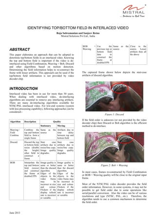
- 1. IDENTIFYING TOP/BOTTOM FIELD IN INTERLACED VIDEO Raja Subramanian and Sanjeev Retna Mistral Solutions Pvt Ltd., India ABSTRACT This paper elaborates an approach that can be adopted to determine top/bottom fields in an interlaced video. Knowing the top and bottom field is important if the video is de- interlaced using Field Combination, Weaving + Bob, Discard and other algorithms based on motion detection. Determining the field information helps to re-construct the frame with lesser artifacts. This approach can be used if the top/bottom field information is not provided by video decoder chip. INTRODUCTION Interlaced video has been in use for more than 50 years. When dealing with interlaced video, de-interlacing algorithms are essential to remove any interlacing artifacts. There are many de-interlacing algorithms available for NTSC/PAL interlaced video. For low-end systems (system with less processing capability), following approaches can be considered:- Algorithm Description Quality Stationary Moving Weaving / Field Combine Combine the top and bottom field to form a single frame Same as the source Artifacts due to time delay between top and bottom field Discard Discard the top or bottom field, resize (double the height) other field to construct a frame Stair case artifacts due to resize/line copy. Image quality degrades. Stair case artifacts due to resize/line copy. Image quality degrades. BOB Interpolate the top and bottom field (resize) and construct the frame at doubled FPS Image quality is same or better than the discard algorithm. Edges of the objects in the video frame may be incorrect in size and colour. Flickers if the display refresh rate is incorrect or variable. Image quality is same or better than the discard algorithm. Edges of the objects in the video frame may be incorrect in size and colour. Flickers if the display refresh rate is incorrect or variable. BOB + Weaving Use the previous top or bottom field data to construct the frame at doubled FPS Same as the source Close to the source. Lesser artifacts than all the above The captured frame shown below depicts the stair-case artifacts of discard algorithm. If the field order is unknown (or not provided by the video decoder chip) then Discard or Bob algorithm is the efficient method to de-interlace. In most cases, frames re-constructed by Field Combination or BOB + Weaving quality will be close to the original input frame. Most of the NTSC/PAL video decoder provides the field order information. However, in some systems, it may not be possible to get field order due to some operations like serial/parallel conversion. Also the video can be of various resolutions and type (NTSC, PAL, etc.). Therefore, the algorithm needs to use a common mechanism to determine the field order. Figure 2: Bob + Weaving Figure 1: Discard June 2013
- 2. Field Dominance Algorithm Each digitized input video frame contains two parts which is received as a top and bottom field with respect to time order. If the field order information from video decoder chip is not available and the de-interlacing algorithm receives an top field first, then re-construction of the frame is illustrated below. In this case the video frames are re-constructed correctly. If the algorithm receives the bottom field as a first field then the field order is reversed. Re-construction of the video frames in such a case is illustrated as below: For Example, YUV 4:2:2 little-endian data with top field dominance will be stored as shown Line 1(top1) → U0 Y0 V0 Y1 U2 Y2 V2 Y3... Line 2(bottom1) → U0 Y0 V0 Y1 U2 Y2 V2 Y3... Line 3(top2) → U0 Y0 V0 Y1 U2 Y2 V2 Y3... Line 4(bottom2) → U0 Y0 V0 Y1 U2 Y2 V2 Y3... . . . Line n → U0 Y0 V0 Y1 U2 Y2 V2 Y3.. In this case the quality of the re-constructed frame is same as the input source. If field order is reversed, then progressively weaved data may look as follows Line 1(bottom1) → U0 Y0 V0 Y1 U2 Y2 V2 Y3... Line 2(top2) → U0 Y0 V0 Y1 U2 Y2 V2 Y3... Line 3(bottom2) → U0 Y0 V0 Y1 U2 Y2 V2 Y3... Line 4(top3) → U0 Y0 V0 Y1 U2 Y2 V2 Y3... . . . Line n → U0 Y0 V0 Y1 U2 Y2 V2 Y3.. The re-constructed frame quality is not good due to the swapped lines. To determine the field order, the algorithm must assume the field order is correct and then interpolate the two consecutive lines of the top fields using the 2-points or 6-points median algorithm and compare each pixel's luminance against the bottom line's pixels. This procedure can be repeated again assuming the field is reversed. Comparing these two helps in identifying the field order. Assuming the luminance values of the frame are arranged in the following order Line 1, y(1) → x1,x2,x3... Line 2, y(2) → x1,x2,x3... Line 3, y(3) → x1,x2,x3... Line 4, y(4) → x1,x2,x3... . Line n-1, y(n-1) → x1,x2,x3...x(m-1),x(m),x(m+1),... Line n, y(n) → x1,x2,x3...x(m-1),x(m),x(m+1),... Line n+1, y(n+1) → x1,x2,x3...x(m-1),x(m),x(m+1),... the top field confidence for any point fi( x(m), y(n) ) point can be calculated by, Figure 4: Field-swap artifacts Figure 3: Proper Field Ordering
- 3. In the above formula, luminance value of column x(m) and row y(n) can compared with the calculated median value(interpolated). We can also calculate the bottom Field confidence by, Sum of all top field confidence gives the total top confidence value for the frame. Similarly the total bottom field dominance values can be calculated by adding all the bottom confidence values . Following formula helps to determine if the field is swapped or not. Once the field information is detected, it is necessary to run this algorithm at regular interval to reaffirm the file order. Accuracy Input Video Data Accuracy (in %) Moving Picture 99 – 100 Still picture (paused video or picture) 95 – 100 Still picture (paused video or frame with same color) >75 Performance Event Timings (in millisecond) Time to determine field order (2 - point mean algorithm running 33 - 99 on 400mhz ARM Cortex-M3 ) Time to detect re-plug and correct the Field order (Algorithm runs every 1000 ms) 1000-3000 CONCLUSION The interpolated video data will approximately be equal to the original data. This method is more reliable to identify the field dominance for most video data and hence improves the picture quality dramatically. 2-point median algorithm can be substituted to reduce the CPU load further. Further, this algorithm is influenced by input video data and the field order may change as a result of the video input cable being removed/re-plugged. So, it's necessary to run this algorithm at periodic interval to correct the field dominance accordingly. About Authors Raja Subramanian is a member of the engineering team at Mistral Solutions Pvt Ltd. He has completed Masters in Computer Science from Bharathidasan University and has 14 years of experience in designing technical solutions in the area of audio, video, storage and user interface for consumer electronic products. His expertise is in the field of autonomous navigation, video surveillance and data security. Sanjeev Retna is a member of the engineering team at Mistral Solutions Pvt Ltd. He has a Bachelor of Engineering degree from Anna University. His expertise is in the field of autonomous navigation, camera and video related products.