1. COPPER TESTING QUICK REFERENCE GUIDE
Testing copper is not an easy task. Knowledge, experience and good analytical skills are required to be able to determine the root
cause of complex copper-loop issues. For this reason, EXFO developed a wide range of intelligent copper testing functions to
help locate, identify and fix issues affecting telecom network performance. From simple validation tests to advanced fault-finding
features, this guide provides an overview of EXFO’s copper test functions and their applications.
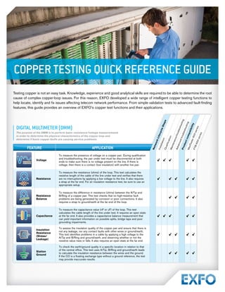
DIGITAL MULTIMETER (DMM)
The purpose of the DMM is to perform basic resistance/voltage measurements
in order to determine the physical characteristics of the copper loop and
determine if basic copper faults are causing service problems.
DIGITAL MULTIMETER (DMM)
The purpose of the DMM is to perform basic resistance/voltage measurements
in order to determine the physical characteristics of the copper loop and
determine if basic copper faults are causing service problems.
FEATURE APPLICATION
Voltage
To measure the presence of voltage on a copper pair. During qualification
and troubleshooting, the pair under test must be disconnected at both
ends to make sure there is no voltage present on the line. If there is
voltage, then there is a contact (low insulation) with another live pair.
Resistance
To measure the resistance (ohms) of the loop. This test calculates the
resistive length of the cable of the line under test and verifies that there
are no interruptions by applying a low voltage to the line. It also requires
a strap at the far end. For an insulation resistance test, be sure to use an
appropriate setup.
Resistance
Balance
To measure the difference in resistance (ohms) between the A/Tip and
B/Ring of a copper pair. This test checks that no high-resistive fault
problems are being generated by corrosion or poor connections. It also
requires a strap to ground/earth at the far end of the loop.
Capacitance
To measure the capacitance value (nF or uF) of the loop. This test
calculates the cable length of the line under test. It requires an open state
at the far end. It also provides a capacitance balance measurement that
can yield important information on possible splits, bridge taps and poor
grounding impairments.
Insulation
Resistance
(Stress/
Leakage)
To assess the insulation quality of the copper pair and ensure that there is
not any leakage, nor any contact faults with other wires or ground/earth.
This test identifies problems in a cable by applying a high voltage to the
A/Tip and B/Ring and ground/earth, and observing whether or not the
resistive value rises or falls. It also requires an open state at the far end.
Station
Ground
To check the earth/ground quality in a specific location in relation to that
of the central office. This test uses A/Tip, B/Ring and ground/earth leads
to calculate the insulation resistance between the wires and the ground.
If the CO is a floating exchange type without a ground reference, the test
may provide inaccurate results.
N
e
t
w
o
r
k
L
i
f
e
c
y
c
l
e
S
t
e
p
s
I
n
s
t
a
l
l
a
t
i
o
n
Q
u
a
l
i
fi
c
a
t
i
o
n
M
a
i
n
t
e
n
a
n
c
e
/
t
r
o
u
b
l
e
s
h
o
o
t
i
n
g
A
d
v
a
n
c
e
d
t
r
o
u
b
l
e
s
h
o
o
t
i
n
g
P
r
o
d
u
c
t
c
o
m
p
a
t
i
b
i
l
i
t
y
M
a
x
T
e
s
t
e
r
6
0
0
s
e
r
i
e
s
F
T
B
-
6
0
0
s
e
r
i
e
s
2. 2 | COPPER TESTING QUICK REFERENCE GUIDE
FREQUENCY TESTING
The purpose of frequency testing is to measure the characteristics of
the pair under test in the frequency domain.
Note
a. Applicable only to the MaxTester 610, MaxTester 635 and MaxTester 635G
FREQUENCY TESTING
The purpose of frequency testing is to measure the characteristics of
the pair under test in the frequency domain.
N
e
t
w
o
r
k
L
i
f
e
c
y
c
l
e
S
t
e
p
s
I
n
s
t
a
l
l
a
t
i
o
n
Q
u
a
l
i
fi
c
a
t
i
o
n
M
a
i
n
t
e
n
a
n
c
e
/
t
r
o
u
b
l
e
s
h
o
o
t
i
n
g
A
d
v
a
n
c
e
d
t
r
o
u
b
l
e
s
h
o
o
t
i
n
g
P
r
o
d
u
c
t
c
o
m
p
a
t
i
b
i
l
i
t
y
M
a
x
T
e
s
t
e
r
6
0
0
s
e
r
i
e
s
F
T
B
-
6
0
0
s
e
r
i
e
s
FEATURE APPLICATION
Load Coil
Detection
To measure the presence of up to five load coils on a copper pair. It is
important to note that load coils were once used to extend the reach of
normal voice (POTS) lines. This test makes sure that a cable is loaded
properly, or when prequalifying DSL loops, it makes sure that all load coils
have been removed from service.
Single-Ended
Attenuation
(SEA)
To measure loss at all frequencies up to VDSL2 (30 MHz) from one end
of the circuit without the use of a FED or second technician. This test
uses a special signal Tx and an advanced algorithm to determine the
attenuation of copper pair over a selected frequency range. The SEA test
is complementary to PSD and serves to verify that the line can support
DSL services.
a
VF
Longitudinal
Balance
To determine how balanced the A/Tip and B/Ring are from each other to
the ground/earth. This test applies a common mode signal to both wires
of a pair and measures the level of noise rejection between them. This
determines the pair quality for the passing service.
WB
Longitudinal
Balance
To measure the ability of a circuit to reject noise across wideband
frequencies. This test is used to evaluate ground conditions, poor splices
or insulation breakdown. It can be used for all types of DSL, but because
the bandwidth of VDSL2 is so much wider than ADSL, this test must be
performed at the maximum frequency of the service being qualified (up to
30 MHz for VDSL2 on the FTB-1; the limit on the MaxTester is 17 MHz).
a
Tx/Rx Tone
To transmit or receive a tone generated to/from the opposite end.
This test uses the Send Tone part (Tx) to transmit a tone over the line
and calculate the insertion loss of the pair in dual-end mode using a
receiver device at the remote end. It also uses the Receive Tone part
(Rx) to calculate the insertion loss of the pair in dual-end mode using a
transmitter device at the remote end.
WB Return
Loss
WB return loss test measures the mismatching of the line impedance with
respect to the ideal impedance across the frequency band. The difference
may be created by pair impairment and it can create problems for
technologies relying to echo cancellation systems like ISDN or SHDSL.
a
RX Tone with
FED
Operators’ processes may require measurement of the insertion loss of
a pair using a dual-end line test (DELT). In this case, it is possible to use
this test in conjunction with the TS125 FED.
a
3. COPPER TESTING QUICK REFERENCE GUIDE |3
NOISE TESTING
The purpotse of noise tests is to perform voice frequency (VF)/
wideband (WB) noise and level measurements.
Notes
a. Applicable only to the MaxTester 610, MaxTester 635 and MaxTester 635G
b. Applicable only to the FTB-1, MaxTester 610, MaxTester 635 and MaxTester 635G
NOISE TESTING
The purpotse of noise tests is to perform voice frequency (VF)/
wideband (WB) noise and level measurements.
FEATURE APPLICATION
VF Noise
To measure the voice-frequency noise on a subscriber’s telephone line.
The industry standard is less than 70 dBm (20 dBrnC) of noise at the
customer’s end.
Power
Influence
To determine the effect of the main (50/60 Hz) field from power cables on
the pair under test. The 50/60 Hz field and its harmonics are measured
and compared to the industry standard of –10 dBm (80 dBrnC)
(maximum value). This helps calculate the amount of noise that is caused
by power generation from the power company.
VF Impulse
Noise
To identify noise sources external to the copper pair. This test determines
the level and number of impulse noise violations in the voice-frequency
band from external sources, like high voltage motors near telephone lines
and microwave ovens. This is a single-end measurement.
WB Power
Spectral
Density
(PSD) Noise
To check the ambient noise on a circuit prior to provisioning to ensure
it will support the rate requested by the customer. This test helps avoid
providing service that will be unreliable and cause further technician visits.
It tests the entire VDSL2 bandwidth (30 MHz).
a
WB Impulse
Noise
To measure the number of noise impulses on a line that is caused by
sources outside the copper plant. A violation can be plotted in an Impulse
Noise Histogram. b
The histogram attaches a time component to the noise
measurement, allowing a technician to determine how many violations
occurred, and more importantly, when they occurred. This is a single-end
measurement.
a
Impulse
Scope
To capture and analyze impulse noises on a line with the option of
performing simultaneous frequency and time domain analysis. This test
allows a technician to define the signature of the noise and locate the
possible source.
Impulse
Duration and
Disruption
(IDD)
To capture and analyze impulse noises on a line with statistical data
to help fine-tune the impulse noise protection (INP) level on ADSL2+/
VDSL2. This test creates a histogram of the distribution of fast and slow
impulses over time with high-level duration and disruption (IDD) times.
NEXT
To measure the near-end crosstalk attenuation between two pairs.
Under good conditions, the crosstalk attenuation of the pairs should be
high. However, in the case of unbalance, split pairs or low insulation,
there could be strong noise from one pair to the other. With the tester
connected to the pairs, this test requires an open state at the far end.
N
e
t
w
o
r
k
L
i
f
e
c
y
c
l
e
S
t
e
p
s
I
n
s
t
a
l
l
a
t
i
o
n
Q
u
a
l
i
fi
c
a
t
i
o
n
M
a
i
n
t
e
n
a
n
c
e
/
t
r
o
u
b
l
e
s
h
o
o
t
i
n
g
A
d
v
a
n
c
e
d
t
r
o
u
b
l
e
s
h
o
o
t
i
n
g
P
r
o
d
u
c
t
c
o
m
p
a
t
i
b
i
l
i
t
y
M
a
x
T
e
s
t
e
r
6
0
0
s
e
r
i
e
s
F
T
B
-
6
0
0
s
e
r
i
e
s