4.main content final copy edited (2)
•Télécharger en tant que DOCX, PDF•
0 j'aime•633 vues

1. The document discusses various engineering drawing codes, symbols, and standards including abbreviations, IS codes, and presentation rules. 2. Welding symbols and their components like arrow lines, reference lines, weld size, finish symbols, and unwelded lengths are defined. Riveted joint types and rivet head forms are also covered. 3. Screw thread terms such as crest, root, pitch, and types including V-thread, square thread, and metric threads are explained. Keys, fasteners, and threaded components like bolts, nuts, and taps are also discussed.

Recommandé
Contenu connexe
Tendances
Tendances (20)
Similaire à 4.main content final copy edited (2)
Similaire à 4.main content final copy edited (2) (20)
Dernier
Dernier (20)
4.main content final copy edited (2)
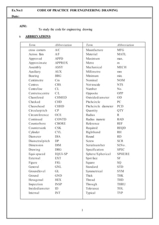
- 1. 1 Ex.No:1 CODE OF PRACTICE FOR ENGINEERING DRAWING Date: AIM: To study the code for engineering drawing i) ABBREVATIONS Term Abbreviation Term Abbreviation cross corners A/C Across flats A/F Approved APPD Approximate APPROX Assembly ASSY Auxiliary AUX Bearing BRG Centimetre Cm Centres CRS Centreline CL Centretocentre C/L Chamfered CHMED Checked CHD Cheesehead CHHD Circularpitch CP Circumference OCE Continued CONTD Counterbore CBORE Countersunk CSK Cylinder CYL Diameter DIA Diametralpitch DP Dimension DIM Drawing DRG Equi-spaced EQUI-SP External EXT Figure FIG. General GNL Groundlevel GL Ground GND Hexagonal HEX Inspection INSP Insidediam eter ID Internal INT Maunfacture MFG Material MATL Maximum max. Metre m Mechanical MECH Millimetre mm Minimum min. Nominal NOM Not toscale NTS Number No. Opposite OPP Outsidediameter OD Pitchcircle PC Pitchcircle diameter PCD Quantity QTY Radius R Radius inanote RAD Reference REF Required REQD Righthand RH Round RD Screw SCR Serialnum ber Sl.No. Specification SPEC Sphere/Spherical SPHERE Spot face SF Square SQ Standard STD Symmetrical SYM Thick THK Thread THD Through THRU Tolerance TOL Typical TYP
- 2. 2 ii) STANDARDCODES Sl.NO IS-CODE DESCRIPTION 1 IS:9609-1983 Lettering on Technical Drawing 2 IS:10711-1983 Size of drawing sheets 3 IS:10713-1983 Scales for use on technical drawing 4 IS:10714-1983 General Principles of Presentation 5 IS:10715-1983 Presentation of threaded parts on technical drawing 6 IS:10716-1983 Rules for presentation of springs 7 IS:10717-1983 Conventional representation of gears on technical drawing 8 IS:11663-1986 Conventional representation of common features 9 IS:11664-1986 Folding of drawing prints 10 IS:11665-1986 Technical drawing – Title blocks 11 IS:11669-1986 General principles of dimension on technical drawing 12 IS:11670-1986 Abbreviation’sforuseinTechnicalDrawing RESULT: Thus the code and symbols of practice for Engineering drawing were studied.
- 3. 3 Ex.No:2 STUDY OF WELDINGSYMBOLS Date: AIM: To study the welding symbols. INTRODUCTION Welding is a process of fastening the metal parts together permanently by the application of heat (fusion welds) or pressure (pressure or forge welding) or both (resistance welding). Both ferrous (steel, cast iron) and Non-ferrous metals (like brass copper and alloy) can be joined bywelding. The welding is cheaper, stronger, easier and faster than riveting. The various types of welding process are a. Gaswelding b. Arcwelding i. Metal Arc Welding(MAW) ii. Gas metal Arc Welding(GMAW) iii. Submerged Arc Welding(SAW) iv. Tungsten Inert Gas Welding (TIG) v. Metal Inert Gas Welding (MIG) c. ForgeWelding d. ResistanceWelding e. ThermitWelding f. High EnergyWelding The welded joints are broadly classified into a. Butt joint b.Lapjoint c. Corner or Fillet joint d. Tee joint e. Edgejoint SYMBOLIC REPRESENTATION OFWELD The standard welding symbol is given below. Arrow Line and referenceLine The position of the arrow line with respect to the weld is of no special significance. The side of the joint on which the arrow line is drawn is called “arrow side”. The side of the joint remote to the arrow line is called “other side”. The reference line has significance on the weld side. If the weld symbol is placed BELOW the reference line, the welding should be done in the “ARROW SIDE”. If the weld symbol is placed ABOVE the reference line, the welding should be done in the “OTHER SIDE”. If the weld symbol is placed both ABOVE and BELOW the reference line, the welding should be done in both the “ARROW AND OTHER SIDES”.
- 4. 4 Basic Weld Symbol The basic symbols recommended by Bureau of Indian Standards (BIS) for specifies the type of weld are shown in the fig1. Basic weld symbols. FIG1. 1.1.3 Size of weld The size of the weld is height of the isosceles triangle in the case of fillet welds. In other cases, the size will be the minimum distance from the surface of the paert of the bottom of penetration. Finish and contour symbol The contour symbols are a. Flat(flush) b. Convex c. Concave Finishing welds other than cleaning shall be indicated by finish symbols. Chipping – C, Grinding – G, Machining – M
- 5. 5 Welded and unweldedlength Length of weld means it is the length to be welded once, after that pitch equal to unwelded length is not welded and this process is continued for the whole length of the side. Weld allround If the weld should be made all round the joint, a circle should be placed at the point connecting the arrow and the reference line. Site weld When some of the welds (the welded structures) are required to be made on site during erection. They should be designed by a filled in circle at the point connecting the arrow and the reference line. RESULT: Thus the welding symbols were studied.
- 6. 6 Ex.No:3 STUDY OF RIVETEDJOINTS Date: AIM: To study the riveted joints. Applications Of RivetedJoints A riveted joint is a permanent type of fastener used to join the metal plates or rolled steel sections together. Riveted joints are extensively used in structural works such as bridges and roof trusses and in the construction of pressure vessels such as storage tanks, boilers, etc. Although welded joints are best suited to several of these applications than the riveted joints, however, riveted joints are ideal in cases where the joints will be subjected to pronounced vibrating loads. Riveted joints are also used when a non-metallic plate and a metallic plate are to be connected together. They are also used when the joints are not expected to be heated while joining as in welding, which may cause warping and tempering of the finished surfaces of the joints. The disadvantage of riveted joints are: (i) more metal is removed while making of the holes, which weakens the working cross sections along the line of the rivet holes, and (ii) weight of the rivets increases the weight of the riveted members. Differences Between A Bolt And ARivet As a fastener, a riveted resembles a bolt, but differs from it in the shape and the application as well. Although the shape of a rivet is similar to that of a bolt, unlike the bolts, it is used as a permanent fastener to withstand shear forces acting perpendicular to its axis, whereas a bolt is used as a temporary fastener to withstand axial tensile forces. Rivet A rivet is a round rod made either from mild steel or non-ferrous materials such as, copper, aluminium, etc., with a head is, and formed at one end during its manufacture and its tail end being slightly tapered. The length of the shank of the rivet must be sufficient enough to accommodate the connection plates and provide enough material for forming a head at its shank end. In general, the shank of the rivet will be equal to sum of the thickness of the connecting plates plus 1.5 to 1.7 times the diameter of the rivet. If, l = length of the shank of the rivet d = diameter of rivet t = thickness of each of the connecting plates then, l = Σt + (1.5 to 1.7)d
- 7. 7 Forms And Proportions Of RivetHeads Various types of rivet heads for the use in general engineering work and boiler work as recommended by the Bureau of Indian Standards. The different proportions of these rivet heads are given in terms of the nominal diameter d of the rivet. The rivet head to be used for general purposes for diameter below 12 mm are specified in the Indian Standard code IS:2155-1962 and for diameters between 12 and 48 mm are specified in the Indian Standard code IS:1929-1961. The rivet heads to be used for boiler work are specified in the Indian Standard code IS: 1928-1961. The rivet heads to be used for ship building are specified in the Indian Standard code IS: 4732- 1968. RESULT: Thus the study of riveted joints was studied successfully.
- 8. 8 Ex.No:4 STUDY OF SCREW THREADS, KEYS ANDFASTENERS Date: AIM: To study the Screw Threads, Keys and fasteners SCREWTHREADS INTRODUCTION A screw thread is a functional element used on bolt, stud, set screw, nut or any other threaded piece or component. Screw thread is a helical groove on a cylinder surface (outer side or inner side). Its function is to transform the input motion of rotation into output motion of translation. If a cylindrical rod is rotated at a constant speed simultaneously if a pointed tool touching the rod moving parallel to the axis of the rod at constant speed, the cut made by tool on the rod will be continuous and of helical form. The helical groove is called “thread” and the threaded rod is called a “screw”. Threads are cut using a lathe. Small size thread is often cut by means of a tool called die. A small size hole is threaded by means of a tool called a tap. The principal uses of threads are, 1. Forfastening 2. Foradjusting 3. For transmittingpower TERMS ANDNOMENCLATURE 1. Crest: It is outer most portion of thethread. 2. Root: It is the inner most portion of thethread. 3. Flank or side: It is the surface of a thread that connects the crest with theroot. 4. Angle of the thread: It is the angle included between the sides of twoadjacent Threads measured on an axialplane. 5. Depth of the thread: It is the distance between the crest and the root measuredat Right angle to the axis. It is equal to half the difference between the outer diameter and the core diameter. 6. Major diameter or outside diameter: It is the diameter of the imaginarycoaxial cylinder, which would bind the crests of an external or internalthread. 7. Minor or core or root diameter: It is the diameter of the imaginary coaxial cylinder, 8. Pitch diameter: It is the diameter of the imaginary coaxial cylinder that canbe Passed so as to cut the thread, that the width of the cut thread will be equal to the Width of thegroove.
- 9. 9 9. Pitch: It is the axial distance between a point on one thread and thecorresponding Point on the next thread. It may be indicated as the distance from crest or from root of two adjacentthreads. 10. Lead: It is the distance measured parallel to the axis from a point on a threadto The corresponding point on the same thread for one complete revolution. In other words, it is axial distance a screw advances in one revolution. When all the threads on a member are built on a single helix it is termed as “single start thread”. It has only one starting point. For a single start thread, the lead and pitch are same. If a quick acting thread is needed, the lead must be large. If a single start is cut with large pitch, the thread depth will also be more, so the amount of material removed is more and the thread will be weakened. To avoid this multiple threads are used when a quick advance is required in a screw pair. Two or more threads are cut side by side around the cylinder on an equal number of parallel helices. It is termed as “Multi start thread”. Lead = number of starts x pitch A common example for multi start thread is the thread on a fountain pen cap. 11. External thread: It is the thread on the outside surface of a member such asbolt, Studs orscrew. 12. Internal thread: It is the thread on the inside surface of a member such as nutor Threadedhole. 13. Right hand thread: Right hand thread if turned clockwise direction advances intoa Threaded hole. It abbreviated asRH. 14. Left hand thread: Left hand thread if turned anticlockwise direction advancesinto a threaded hole. It abbreviated asLH. DIFFERENT THREAD PROFILES Threads are standardized to permit to interchangeability of bolts and nuts of the same nominal diameter.The profile of as crew thread is based on its use. The two main kinds are„ V‟ and square with various modifications. When the thread has a„ V‟cross-section it is called a„V‟thread and when it has square cross section it is called a squarethread.
- 10. 10 DIFFERENCE BETWEEN „V‟ AND SQUARETHREADS „V‟ THREADS SQUARE THREADS 1. V - threads have inclined flanks making an angle betweenthem. 2. V – threads have a larger contact areaproviding more frictional resistance to motion. So they are more suitable forfastening. 3. V – threads are stronger than the square threads. 4. V – threads are cheap because they can be cut easily by a die or onmachines. Examples for V – threads are the thread used in bolts, nuts andstuds. 1. The flanks of square threads are perpendicular to thread axis and parallel to eachother. 2. Square threads offer less friction to relative motion. The normal force between the threads acts parallel to the axis with zero radial components. So they are suitable for power transmission. 3. Square threads have only half the resisting the power, resting the shearingaction. 4. Square threads arecostly. Examples for square threads are lead screw of a lathe, screw jacketc., V- THREADS British standard whit worth thread(BSW) This thread was introduced by Sir Joseph whit worth, and was standardized as British standard thread. It has a thread angle of 55 degree and is rounded equally at crest and roots. British Association threads (B.AThreads) The angle between flanks is 47.5 degree. These threads are to supplement BSW and have fine pitches. They are used on screws for precision work. American standard threads (or) sellersthread The thread angle is 60 degree and both the crests and roots are kept flat. The sellers thread has been in use in USA andCanada.
- 11. 11 Unified screw threads The countries UK, U.S.A and Canada came to an arrangement for a common screw thread system with the included angle of 60 degree and designated as unified screw thread in the year 1949. The thread on the bolt is rounded off at the crest and root and the thread in the nut is rounded off at the root but the crest is leftflat. This thread is very important in the motor and aeroplane industries and in chemical engineering. Unified thread can be either coarse (UNC) or fine (UNF) and unified national extra fine (UEF). ISO MetricThread This is Indian standard thread for ISO (International Standard Organization). The included angle is 60 degree and the crests are flat and roots are round. Metric threads are grouped into diameter pitch combination differentiated by the pitch applied to specific diameters. There are coarse, constant, fine pitch series available. ISO metric threads are defined by nominal size (Basic major diameter) and pitch both expressed in millimeters. For example, a 10mm diameter, 1.25 pitches is expressed as M10x1.25. SQUARETHREADS Basic squarethread The sides of these threads are normal to the axis and parallel to each other. The depth and the thickness of the thread are equal to half pitch. A square thread is designated by the letter SQ followed by nominal diameter pitch. For example a square thread of nominal diameter 30mm and pitch 6mm is designated as SQ 30 X 6. AcmeThread Itisamodifiedfromofsquarethread.Itiseasiertocutandismuchstrongerthansquarethread.Ithasa29 degree thread angle. This inclined sides of the thread facilitate quick and early engagement anddisengagement. It is used for power screws like lead screw of lathe, jackscrews, bench vices and valve operating screws. ButtressThread The profile of this thread is a combination of square and V- threads. It combines the low frictional of square and ability to transmit power of square thread and the strength of V – thread. It is used to transmit load in uni-direction. These threads are used in screw press, vices.
- 12. 12 KnuckleThread It is also a modification of square thread. The sharp corners of square thread are rounded off. This thread is used where heavy wear rough use is expected. The thread can be rolled or cast easily. It is used in railway carriage coupling screws, light bulbs and sockets, bottle caps etc and also objects made of brittle materials as glass, plastic, porcelains etc.
- 13. 13 KEYS Introduction: A machine runs by the power supplied to it by a prime mover such as motor, engine etc;. This power is transmitted from prime mover to the machine through a coupler which couples shaft of the prime mover and themachine. Within the machine the power from the main shaft is transmitted to the other elements such as gears, pulleys and belts. These elements have to be mounted on these shafts and there should not be any relative motion between the machine element and shaft for effective power transmission. The most commonly employed method to connect a shaft and a machine parts is to drive a small piece of metal s known as KEY. To drive a key axial grooves are cut both in the shaft end the part mounted on it. The groove in the shaft is called the “KEYWAY”. CLASSIFICATION OFKEYS: Keys are classified into three types 1. Taperkeys 2. Parallel (or) featherkeys 3. Special purposekeys COMPARISION BETWEEN TAPER KEY AND PARALLELKEY: TAPER KEY PARALLEL KEY 1. It is of rectangular cross section having uniform width and tapering thickness. 1. It is of rectangular cross section having uniform width and tapering thickness. 2. These are used to transmit only the turning moment between the shaft and hub without any relative axial motion between them. 2. These are used to transmit moment between the shaft and hub withthe provision to allow a small sliding axial motion. 3. examples for taper keys are i. Taper sunk key ii. Hollow saddle key flatsaddle iii. Gib head key 3. examples for parallel keysare i. Parallel sunk key ii. Pegkey iii. Single head key iv. Double headkey Special purpose keys are used for specific application (ex) Woodruff key, pin key. Keys can also be classified as Heavy duty keys sunkkeys&Light duty keys saddle keys, pin (or) roundkeys. Taperkeys:
- 14. 14 A sunk taper key is of rectangular or square cross section of uniform width having its bottom surface straight and top surface tapered. So in the shaft flat key seat is made and in the hub tepered key is made to accommodate thekey. If D is the diameter of the shaft inmm W = Width of thekey T = thickness of the key W = 0.25D+2mm T = 0.66W Standard taper = 1:100 Saddlekey: Saddle keys are of two types a. Hollow saddle key b. Flat saddle key Hollow saddlekey: A hollow saddle key is of uniform width and varying thickness having its upper side flat and the bottom side curved (hollow) so as it sit on a shaft. The key way is cut only in the hub and the key holds the shaft by frictiononly. Width of the key =0.25D+2mm Nominal thickness =0.33W Standardtaper =1:100 Flat saddlekey: A flat saddle key is smaller is similar to a hollow saddle key except that its bottom side is flat. The keys sits over the flat surface formed on the flat shaft, and fits into the keys way in the hub. Width of the key =0.25D+2mm Nominal thickness =0.33W Standardtaper =1:100 2.3.3. Gib head key: When a tapered sunk key is used it can be removed by striking at its exposed thin end. If this end is not reachable, a head is called “GIB” is provided with the sunk taper key at its thicker end it is called GIB-HEAD key. To remove the key, a wedge is forced vertically in the gap between the key and the hub.Width of thekey.
- 15. 15 W =0.25D+2mm Nominal thickness T =0.33W Height of gib head h =1.75T Width of the gibheadb=1.5T Standardtaper =1:100
- 16. 16 THREADEDFASTENERS INTRODUCTION Threaded fasteners are temporary fasteners, which hold the parts together through the medium of a screw thread. These are used in pairs for their action (for example, a nut and a bolt). They have the advantage over permanent fasteners of allowing assembly of parts when required. A wide variety of threaded fasteners are in use. Some of them are standardized and others are made for special use. COMMON TYPE OF THREADEDFASTENERS The five types of threaded fasteners in common use are Bolt Stud Cap screw Machinescrew Setscrew All these with external threaded and used in combination with another having corresponding internal threads (eg) a nut or a tapped hole. BOLTS A bolt is a metal having a head at one end and a threaded portion to a definite length on other end. The head is formed by forging or machining. The bolt is admitted through holes in the parts, which are to be fastened. The projected thread end of the bolt admits a corresponding nut from the other side. Tightening the bolt by turning gives necessary clamping grip to hold the partstogether. Bolts and nuts of various shapes are used for different purpose but the hexagonal head and square head are very common. Although, the square shape provides better spanner grip than the hexagon, but needs one fourth of a turn to bring it into the same position for inserting spanner again, whereas a hexagon need only one sixth of a turn and hence provided. The sharp corners on the external flat end faces of bolt heads and nuts are chamfered conically at 30ᴼ to ensure safety of the user. To facilitate early insertion of the nut over the bolt, the threaded holes in the nut are countersunk. Three dimensions are usually sufficient for simplified representation of a bolt The bolt shank diameter (d) The bolt length (l) The length of a threaded portion of the shank (b)
- 17. 17 EMPIRICAL PORTIONS OF HEXAGON AND SQUARE HEAD BOLT &NUT DETAILPROPORTION: Nominaldiameter d =size of bolt ornut,mm Widthacrossflats s =1.5d+3mm Widthacrosscorners e =2d Thickness ofbolthead k =0.8d Thicknessof nut n=0.9d Rootdiameter d1 =d-(2*depth of thread) Length ofthebolt l =asspecified Threadlength b =2d+6mm (forl<150mm) =2d+12mm (for l>150mm) Chamfer ofboltend Z =depth of thread*45(degree) (or) =0.1d Chamfer angle of bolt head & nut 30(degree) 3.2.2.1 DRAWING OF HEXAGONAL NUT AND BOLT STEP: 1 Draw the shank of the bolt equal to the given diameter (d) and length (l).The thickness of the bolt head equals to 0.8d and the thickness of nut equal to 0.9d are marked. Measure the width across corners equal to 2d and complete the three faces of the bolt head and nut in these lines. The right hand view of the bolt and nut assembly is drawn as follows with any point on the axis as centre and radius equal to draw a thin circle. A hexagon is inscribed inside this circle. The chamfer circle is drawn as a thick circle inside the hexagon touching all its sides. STEP: 2 The chamfer arcs in three face view of bolt head and nut are drawn as follows. From the point O1, drawn an arc (more than semi circle) radius equal to half of the across flats width. It cuts the bolt axis at c2. From c2, again draw an arc equal to half of the across flat width. This arc cuts the bolt axis at c3. These two arcs are intersecting at c4 and c5. From c3, draw the chamfer arc in the centre face, radius equal to across flats width. This arc cuts the edges of the other two faces. From c4 and c5, draw the other two chamfer arcs. STEP: 3 The chamfer lines on the side faces of the three face views of the bolt head and nut are drawn through the points p and q inclined at 30ᴼ to the flat faces of the bolt. The end of the bolt is chamfered 0.1d*45ᴼ . The threaded portion of the shank is indicated, by drawing two thin lines at a distance equal to d1=0.9d.the root circle in the right view is represented by a thin three-fourth of a circle of diameter 0.9d.
- 18. 18 STEP: 4 The two face view of the bolt head and nut is as follows. The width of the bolt head in this view is equal to the across flats width. Draw an arc radius equal to half of the across flats width from the point O1. Two arcs with radius equal to across flats width from the corners.These two arcs cut the first arc at two points 02 and 03. From 02 and 03 the chamfer arcs are drawn. DRAWING OF SQUARE HEAD BOLT AND NUT: STEP:1 Draw the shank of the bolt equal to the given diameter d and the length of the bolt. The thickness of the bolt head is equal to 0.8d and the thickness of the nut is equal to 0.9d are marked. The right hand view of the bolt and nut assembly is drawn as follows. With any point 01 on the axis as centre and diameter equal to 1.5d+3mm draw a chamfer circle with its sides inclined at 45degree to the axis. Projectthecorners1and2togettogetpoint‟sp. STEP: 2 From the point 01 draw an arc radius equal to half of the across corners width. From the corners, draw two arcs radius equal to half of the across corners width. These two arcs cut the first arc at two points 02 and 03. From 02 and 03 the chamfer arcs are drawn. STEP: 3 The chamfer line is drawn at 30degree to the flat face of the bolt head and nut. The threaded portion on the shank of the bolt is indicated by drawing two thin line spaced at a distance equal to the root diameter d1=0.9d. The root circle in the right view is represented by a thin three- fourth of a circle with center 01 and diameter 0.9. The end of the bolt is chamfered to 0.1d*45degree. Special Types ofBolts: In practice various types of bolts than the hexagon and square head bolts are used in where the bolt head cannot be held by the spanner when the nut is turned on or off the bolt. The rotation of the bolt prevented by a stop pin or a snug or a square neck provided below the head. Cylindrical or Cheese HeadedBolt: The head of this type of bolt is of cup shape and the rotation of the bolt head is prevented by a stop pin. The stop pin may be driven into the shank with its axis perpendicular to the axis of the bolt. The stop pin may also be driven into the head adjacent to the shank with its axis parallel to the axis of the bolt. These types of bolt heads are used in the big ends of the connecting rods, eccentrics, cross heads etc...
- 19. 19 Cup Or Round HeadedBolt: Two types of cup head bolts are available. In one type, a snug is provided which prevents the rotation of bolt head. The other type, a square neck is provided which will fit into the square hole provided in the bearing surface and thus prevents the rotation of the bolthead. Counter Sunk HeadBolt: The counter sunk head bolts are used when the bolt head must not project and foul with surfaces. The counter sunk bolt is provided with a stop pin of square cross section integral with the head. The other type of counter sunk bolt is provided with the square neck below the head. This type of bolt is also called as “coach bolt”. I-HeadBolt: Theheadofthisboltislikeletter„i‟.Theseboltsareusedinbearinghousingandinglandspacking.Thesebolts are used in setting work on machine tool tables. The i head of the bolt can slide, to the required position through the i slots cut on the m/c table. EyeBolt: The head of the bolt is in the form of circular form of rectangular cross section. It is generally used in the inspection covers, lids etc..., Which have to be opened and closed frequently. Lifting EyeBolt: The lifting eye bolt, having a circular ring of circular cross section as head. A flat circular portion, integral with a head is also provided. This type of bolt is used for lifting a heavy machine such as motors, pumps, turbine, electrical generators etc., This bolt is screwed in a threaded hole provided for this purpose , on the top of the machine directly above the centre of gravity so that while lifting the machine does not change from its usual workingposition. HookBolt: The hook bolt has its head comprising of a square neck and projection. The shank of the bolt passes through a hole in one of the fastening pieces and the other piece comes under the bolt head and is supported by it .
- 20. 20
- 21. 21 Different types of Rivet HeadsFig NUTS A nut is a device having internal threads used in combination with a bolt or stud, having external threads to fasten parts together. It is screwed on the threaded end of the bolt or stud and the head of the bolt is drawn closer to hold and tighten the parts to be joined. Nuts are usually made in form of hexagonal or square prism, however various other types of nuts are also used for the specified purposes, which are suitable for a particular type of work. These special types of nuts are described here. SLOTTED NUT OR RINGNUT On the cylindrical surface of the nut number of slots parallel to the axis are cut. The nut is operated by a spanner. These are used in large screws for small pitches where adjustment by a spanner isconvenient. KNURLEDNUT It is cylindrical nut with knurled curved surface. The nut is used when finger tightness and quick turning on or off is desired as in the case of terminals of electricapparatus. WINGNUT: This type of nut is used for light duty only. It is used wherever the nut is required to be frequently turning on or off. The nut is operated by thumb and finger i.e., without the use of a spanner. The main objection for using this type of locking is that the hole drilled in the bolt reduces its strength considerably. The other equally important objection is that after continuous use owing to the stretch of the bolt the split pin may not rest on the top face of the nut which may reduce the locking effect.
- 22. 22 SPLIT PIN LOCKING USING SLOTTEDNUT: In this method a slotted nut is used instead of the ordinary nut. The slotted nut has slots cut through the opposite parallel hexagonal faces. When the bolt is fully tightened, one set of slots on the opposite faces will come in line with the hole in the bolt. The split pin is inserted through the slots in the nut and the hole in the bolt and then open ends of the split pin are opened. SPLIT PIN LOCKING USING CASTLENUT: In the slotted nuts, the number of effective threads is reduced due to the slot which reduces the strength of the nut considerably. Therefore instead of cutting the slots within the effective depth, they are cut in the extra cylindrical projection provided at the top of the nut. This type of nut is called castle nut. The castle nuts are used on the wheel shafts of automobiles. In the reassembly of the slotted or castle nut, the slots may not come in the alignment with the hole in the bolt. In such cases, the nut is removed from the bolt and its lower face is filled until it can be screwed tightly so that one set of slots come in alignment with the hole in the bolt. SET SCREW LOCKING USING GROOVEDNUT: A hexagonal nut provided with a cylindrical grooved collar at its lower end is called ring or grooved nut. The end of the bolt hole is counter bored to receive the cylindrical lower grooved portion of the nut. Locking of the nut is done by a setscrew screwed through the nearest face of the work piece. The projection dog-end of the set-screw enters the groove in the cylindrical portion of the nut and prevents the slacking ofthenut. This method of locking is possible if the bolt hole is close to the nearest vertical edge as in the case of marine engine connecting rods. When the bolt hole is not close to the vertical edge of the work piece, this nut is used in conjunction with separate collar. The dowel pin screwed in the bearing surface prevents the rotation of the collar. SCREW PINLOCKING: A nut may be locked by screw pin, screwed in the bearing surface adjoining the nut touching one of the lateral faces of the nuts. This type of locking is employed when the nut is expected without any adjustment for a long time. In this method of locking first the nut is screwed on and then a screw pin is screwed into a threaded hole in the bearing surface adjoining to one lateral vertical faces of the nut. 3.4. LOCKING BY A LOCK PLATE: This type of locking is employed in the heavy engineering work, as in the case of connecting rod, wheel shafts etc. the plate is grooved in such a way that the grooves in the plate receive the hexagonal corners of the nut at every 30˚ rotation. The plate is fixed to the bearing surface by a tap bolt screwed intoit.
- 23. 23 3.4.1 LOCKING BY A TAP WASHER: A tap washer provided with a rectangular projection is called tab washer. This method of locking of nut or bolt head is suitable when the nut or bolt head is tightened and the tab and the projection portion of the washer itself are bent against the vertical edge of the work piece and one of the lateral faces of the nut or bolt head. STUD OR STUDBOLT: Stud is a round bar threaded on both its ends. An undesirable feature of a tab bolt fastening is the tendency to damage the threads in the holes when the bolts are frequently removed and replaced, especially when the screwed holes are in the iron and aluminum alloys, this disadvantage are overcome by the use of stud bolts.It has threads on both ends so that one of the pieces, being held together, must be threaded to replace the head. The stud bolt is screwed tightly into the threaded part by a special locknut device, until it jams. The studs becomeanassemblyguidebymeansofwhichtheotherpart,whichisdrilledbutnotthreaded,iseasilyplace din position. A nut screwed on the other end of the stud bolt holds the two parts together. The end of the square neck, at the center, facilitates gripping of stud while screwing or unscrewing. SETSCREWS Setscrews are used as semi permanent fasteners to hold a collar, sleeve, pulley or on a shaft against rotational or translation forces. In contrast to most fastening device, the setscrew is essentially a compression device. Forces developed by the screw point during tightening produce a strong clamping action that resists relative motion between assembled parts. The basic problem in setscrew selection is in finding the best combination of setscrew form, size, and point style providing the required holding power. Set screws are categorized by their form and the desired point style. Selection of specific, form or point is influenced by functional by functional, as well as other considerations. The conventional approach to setscrew selection is usually based on a rule of thumb that the setscrew and key are used together; the screw diameter should be equal to the width of the key. CAP SCREW Cap screws are similar to bolts in that they have a head on one threads on the other. But they widely in the method of holding two parts together. The bolt keeps two parts between the head and the nut, and the cap- screw is threaded in one of the parts, thus clamping another part between the head threaded part. The cap screws are manufactured in several styles of head. The point of all cap screw is flat surface and to a depth equal of the threaded on it.
- 24. 24 MACHINESCREWS These are similar in function and operation to cap screws, but are usually smaller in diameter. Materials: for general engineering purpose, nuts and screws are made of mild steel (MS). However, copper and its alloys, aluminum alloys, etc are also alloys, etc are also used for also used for special purpose in their manufacture. FOUNDATIONBOLTS For securing heavy machines to concrete foundations, special types of bolts known as foundation bolts are used. Positions of bolt holes are marked either from a temple or from a template or from the machine itself, and holes bored out in the floor, sufficiently large enough to allow the bolt to be suspended freely in positions while the cement concrete is poured around to fill up the space. When the cement concretes sets the bolt will be firmly secured in the ground. Fig. Foundation Bolts RESULTS: Thus the studies of Screw threads, keys and fasteners were studied.
- 25. 25 Ex.No:5 STUDY OF DRAFTING SOFTWARE(AUTOCAD) Date: AIM: To study the AUTOCAD Software. Sl.No Command Description 1. OPEN Opens an existing drawing file 2. ARC Creates an arc 3. ARRAY Creates multiple copies of objects in a pattern 4. BHATCH Fills an enclosed area or selected objects with a hatch pattern 5. BLOCK Creates a block definition from objects you select 6. BREAK Erase parts of object or splits an object in two 7. CHAMFER Bevels the edges of object 8. CHANGE Changes the properties of existing objects 9. CIRCLE Creates a circle 10. COLOR Defines color for new objects 11. COPY Duplicates objects 12. DIVIDE Places evenly spaced point objects or blocks along the length or perimeter of an object 13. DONUT Draws filled circles and rings 14. ELLIPSE Creates an ellipse or an elliptical arc 15. ERASE Removes objects from a drawing 16. HATCH Fills a specified boundary with a pattern 17. HATCHEDIT Modifies an existing hatch object 18. EXTEND Extends an object to meet another object 19. INSERT Places a named block or drawing into the current drawing 20. LAYER Manages layers and layer properties 21. LINE Creates straight line segments 22. LINETYPE Creates, loads, and set line types 23. OFFSET Creates concentric circles, parallel lines, and parallel curves 24. FILLET Rounds and fillets the edges of objects 25. MIRROR Creates a mirror image copy of objects 26. MOVE Displaces objects a specified distance in a specified direction 27. MSLIDE Creates a slide file of the current view port in model space, or of all view ports in paper space.
- 26. 26 28. LTSCALE Sets the line type scale factor 29. PAN Moves the drawing display in the current view port 30. OOPS Restores erased objects 31. PLINE Creates two-dimensional polylines 32. POINT Creates a point object 33. POLYGON Creates an equilateral closed polyline 34. PROPERTIES Controls properties of existing objects 35. MTEXT Multiline text 36. ORTHO Constrains cursor movement 37. OSNAP Sets object snap modes 38. REDRAW Refreshes the display in the current view port 39. REGEN Regenerates the drawing and refreshes the current view port 40. ROTATE Rotate 41. SCALE Enlarges or reduces selected objects equally in the X,Y, and Z directions 42. SCRIPT Executes a sequence of commands from a script 43. SKETCH Creates a series of freehand line segments 44. SPLINE Creates a quadratic or cubic spine (NURBS) curve 45. TEXT Displays text on screen as it is entered 46. UNDO Reverse the effect of commands 47. ZOOM Increases or decreases the apparent size of objects in the current view port 48. AREA Calculates the area and perimeter of objects or of defined areas 49. LTSCALE Sets the line type scale factor 50. BACKGROUND Sets up the background for your scene 51. BASE Sets the insertion base point for the current drawing 52. BLIPMODE Controls the displays of marker blips 53. BLOCKICON Generates preview images for blocks created with release 14 or earlier 54. CHPROP Changes the color, layer, line type, scale factor, line weight, thickness, and plot style of an object 55. CLOSE Closes the current drawing 56. DBLIST Lists database information for each object in the drawing 57. DDEDIT Edits text and attribute definitions 58. DDPTYPE Specifies the display mode and size of point objects
- 27. 27 59. DELAY Provides a timed pause within a script 60. DIM AND DIM Accesses dimensioning mode 61. DIMALIGNED Creates an aligned linear dimension 62. DIMANGULAR Creates an angular dimension 63. DIMBASELINE Creates a linear, angular, or ordinate dimension from the baseline of the pervious dimension or a selected dimension 64. DIMDIAMETER Creates diameter dimensions for circles and arcs 65. DIMEDIT Edit dimensions 66. DIMLINEAR Creates linear dimension 67. DIMORDINATE Creates ordinate point dimensions 68. DIMOVERRIDE Overrides dimension system variables 69. DIMRADIUS Creates ordinate point dimensions 70. DIMSTYLE Creates and modifies dimension styles 71. DIST Measures the distance and angle between two points 72. DWGPROPS Sets and displays the properties of the current drawing 73. FILL Controls the filling of multi-lines, traces, solids, all hatches and wide polylines 74. FILTER Creates reusable filters to select objects based on properties 75. ID Displays the coordinate values of a location 76. LIST Displays database information for selected objects 77. MASSPROP Calculate and displays the mass properties of regions or solids 78. MENU Loads a menu file 79. MENULOAD Loads partial menu files 80. MENUUNLOAD Unloads partial menu files 81. OPTIONS Customizes the AutoCAD settings 82. PLAN Displays the plan view of a user coordinate system 83. PLOT Plots a drawing to a plotting device of file 84. SHADEMODE Shades the objects in the current view port 85. SNAP Restricts cursor movement to specified intervals 86. SPELL Checks spelling in a drawing 87. VLISP Displays the Visual LISP interactive development environment(IDE) RESULTS: Thus the AutoCAD software was studied.
- 28. 28
- 29. 29 Ex.No:6 BASIC 2D DRAWING AUTO CAD-USAGE OF COMMANDS Date: AIM: To understand drawingstandards Draw basic sketches and constraint them using Geometrical and Dimensionalconstraints PROCEDURE: Open Auto CAD; Draw the Shape given in the Fig.1. Add relations and Smart dimensions and make sure that the Sketch is Fullyconstraint Change the dimensions according toFig.1 Repeat the same for Fig.2 toFig.6 COMMANDS USED: Line, Circle, Arc, Fillet, Trim, Smart Dimension, Relations, Show, View HARDWARE CONFIGURATION: Processor : Pentium IV Motherboard : Intel Hard disk : 80 GB Ram : 1 GB Input device : Keyboard & Mouse Output device : Laser jet printer SOFTWARE USED : SOLIDWORKS 2015 OPERATING SYSTEM: Windows XP Result: The basic sketches were drawn using AUTOCAD as shown in Figures and the required parameters were added to modify the dimensions at later stage if necessary.
- 30. 30
- 31. 31 Ex.No:7 BASIC 2D DRAWING AUTO CAD-DETAILED DRAWING Date: AIM: To understand drawingstandards Draw basic sketches and constraint them using Geometrical and Dimensionalconstraints PROCEDURE: Open Auto CAD; Draw the Shape given in the Fig.1. Add relations and Smart dimensions and make sure that the Sketch is Fullyconstraint Change the dimensions according toFig.1 Repeat the same for Fig.2 toFig.6 COMMANDS USED: Line, Circle, Arc, Fillet, Trim, Smart Dimension, Relations, Show, View Result: The basic sketches were drawn using AUTOCAD as shown in Figures and the required parameters were added to modify the dimensions at later stage if necessary.
- 32. 32 PLUMMER BLOCK
- 33. 33 Ex.No:8 2DDRAWING AUTOCAD - PLUMMER BLOCK Date: AIM: To understand drawingstandards Draw basic sketches and constraint them using Geometrical and Dimensionalconstraints PROCEDURE: Open Auto CAD; Draw the Shape given in the Fig.1. Add relations and Smart dimensions and make sure that the Sketch is Fullyconstraint Change the dimensions according toFig.1 Repeat the same for Fig.2 toFig.6 COMMANDS USED: Line, Circle, Arc, Fillet, Trim, Smart Dimension, Relations, Show, View RESULT: The basic sketches were drawn using AUTOCAD as shown in Figures and the required parameters were added to modify the dimensions at later stage if necessary.
- 34. 34 Ex.No: 9 2D
- 35. 35 DRAWING AUTOCAD –NON RETURN VALVE Date: AIM: To understand drawingstandards Draw basic sketches and constraint them using Geometrical and Dimensionalconstraints PROCEDURE: Open Auto CAD; Draw the Shape given in the Fig.1. Add relations and Smart dimensions and make sure that the Sketch is Fullyconstraint Change the dimensions according toFig.1 Repeat the same for Fig.2 toFig.6 COMMANDS USED: Line, Circle, Arc, Fillet, Trim, Smart Dimension, Relations, Show, View RESULT: The basic sketches were drawn using AUTOCAD as shown in Figures and the required parameters were added to modify the dimensions at later stage if necessary.
- 36. 36 Ex.No:10 3D GEOMETRIC MODELING USING SOLIDWORKS Date: AIM: To create 3D models of various parts using SOLIDWORKS. PROCEDURE: 1. The modeling concepts – Solid modeling, Surface modeling were trailed in Auto CAD/CATIA by creating 3D model of Sleeve and cotter Joint-connecting rod, sleeve, cotter. 2. The options available in each Feature command are tried to understand the capabilities of each command 3. Design Methods: Bottom-up Design, Top down Design are discussed 4. Assembly of Sleeve and Cotter Joint was created using Bottom-up design approach COMMANDS USED: 5. Sketcher Commands: Line, Circle, Arc, Fillet, Trim, Smart Dimension, Relations, Show, and View 6. Features Commands: Extrude (pad) and Cut, Revolve (shaft), Sweep, and Loft, Fillet/Round, Chamfer, and Draft, Hole - Simple and Hole Wizard, Hole Series, Scale, Shell, Rib, Dome, Freeform, Shape, Deform, Indent, Flex, Pattern and Mirror, Curves, Fastening Features PROCEDURE: 1. Description of Extrude Feature: Toolbar: Features > Extrude. Using this tool, the sketch is extruded through required direction. I. Select a sketch plane. 1. Extrude the sketch perpendicular to sketch plane 2. Sketch a 2D profile of the model
- 37. 37 Fig5: Solid works Plane display II. Extruded Boss Feature: It Adds material to the part and requires a sketch. III. Extruded Cut Feature: It Removes material from the part and also it requires a sketch. IV. Fillet Feature: Rounds the edges or faces of a part to a specified radius.
- 38. 38 Procedure for Extrude: 1. Select a sketch plane.(Front, top or Side) 2. Sketch a 2D profile of the model. 3. Dimension the model using Smart Dimension icon. 4. Check the sketch is fully defined. 5. Extrude the sketch perpendicular to sketch plane. 6. Use extruded cut feature to cut the solid as given in the drawing. 2. Descriptionof Revolve Feature: Command Manager: Features > Revolved Boss/Base Menu: Insert > Boss/Base > Revolve Toolbar: Features > Revolved Boss/Base. Using this tool, the sketch is revolved about the revolution axis. The revolution axis could be an axis, an entity of the sketch, or an edge of another feature to create the revolved feature. Note that whether you use a centerline or an edge to revolve the sketch, the sketch should be drawn on one side of the centerline or the edge. After drawing the sketch, as you choose this tool, you will notice that the sketching environment is closed and the part modeling environment is invoked. Similar to extruding the sketches, the resulting feature can be a solid feature or a thin feature, depending on the sketch and the options selected to be revolved. If the sketch is closed, it can be converted into a solid feature or a thin feature. However, if the sketch is open, it can be converted only into a thin feature.
- 39. 39 Fig:6 Sketch of piston to be revolve Fig: 7 Revolve Property Manager Fig:8 Feature Created after revolving to 360 Procedurefor Revolve: 1. Select a sketch plane.(Front, top or Side) 2. Sketch a 2D profile of the model. 3. Dimension the model using Smart Dimension icon. 4. Check the sketch is fully defined. 5. Revolve the sketch. 3. Description of RIB Feature: Command Manager: Features > Rib Menu: Insert > Features > Rib Toolbar: Features > Rib Ribs are defined as the thin walled structures that are used to increase the strength of the entire structure of the component, so that it does not fail under an increased load. In Solid Works,
- 40. 40 the ribs are created using an open sketch as well as a closed sketch. To create a rib feature, invoke the Rib Property Manager and select the plane on which you need to draw the sketch for creating the rib feature. Draw the sketch and exit the sketching environment. Specify the rib parameters in the Rib Property Manager and view the detailed preview using the Detailed Preview button. The Rib tool is invoked by choosing the Rib button from the Features Command Manager or by choosing Insert > Features > Rib from the menu bar. After invoking the Rib tool, draw the sketch and exit the sketching environment. Fig:9 Rib construction procedure Procedurefor RIB: 1. Select a sketch plane.(Front, top or Side) 2. Sketch a 2D profile of the model. 3. Dimension the model using Smart Dimension icon. 4. Check the sketch is fully defined. 5. Extrude the sketch. 6. Using Rib Feature complete the model. 4. DESCRIPTION OF SHELL FEATURE: It Removes the material from the selected face. It Creates a hollow block from a solid block. Very useful for thin-walled, plastic parts. You are required to specify a wall thickness when using the shell feature.
- 41. 41 Fig: 10 Shell feature Procedure for Shell: 1. Select a sketch plane.(Front, top or Side) 2. Sketch a 2D profile of the model. 3. Dimension the model using Smart Dimension icon. 4. Check the sketch is fully defined. 5. Extrude the sketch. 6. Select the face in which you are going to draw the cut profile. 7. Make that plane to normal to you. 8. Sketch the cut profile & dimension it. 9. Use Extruded cut feature remove the portion. 10. Select the Shell feature. 11. Select the face in which material to be removed using shell. 12. Specify the shell thickness RESULT: The 3D models of parts are created using SOLIDWORKS.
- 42. 42 ASSEMBLY IN SOLID WORKS An assembly design consists of two or more components assembled together at their respective work positions using the parametric relations. In SolidWorks, these relations are called mates. These mates allow you to constrain the degrees of freedom of the components at their respective work positions. To proceed to the Assembly mode of SolidWorks, invoke the New SolidWorks Document dialog box and choose the Assembly button as shown in Figure below. Choose the OK button to create a new assembly document; a newSolidWorks document will be started in theAssembly mode Command Manager: Assemblies > Insert Components Menu: Insert > Component > Existing Part/Assembly
- 43. 43 PLACING COMPONENTS IN THE ASSEMBLY DOCUMENT Command Manager: Assemblies > Insert Components Toolbar: Assembly > Insert Components When you start a new SolidWorks document in the Assembly mode, the Insert Component Property Manager will be displayed as below which enable us to insert the component into assembly file. Fig:12 Insert component Manager ASSEMBLING COMPONENTS: After placing the components in the assembly document, it needs to assemble them. By assembling the components, we have to constrain their degrees of freedom. As mentioned earlier, the components are assembled using mates. Mates helps to precisely place and position the component with respect to the other components and the surroundings in the assembly.
- 44. 44 It is used to define the linear and rotary movement of the component with respect to the other components. In addition, it is possible to create a dynamic mechanism and check the stability of the mechanism by precisely defining the combination of mates. There are two methods of adding mates to the assembly. The first method is using the Mate Property Manager and the second and the most widely used method of adding mates to the assembly is using the Smart Mates.
- 45. 45
- 46. 46 Ex.No:11 ASSEMBLY OF FLANGE COUPLING USING SOLIDWORKS Date: AIM: To create 3D models of various parts using SOLIDWORKS. To Create the Assembly of Flange Coupling using SOLIDWORKS. To understand the type of fits and tolerances used in Assembly. PROCEDURE: The modeling concepts – Solid modeling, Surface modeling were trailed in SOLIDWORKSby creating 3D model of Flange Coupling. The options available in each Feature command are tried to understand the capabilities of each command Design Methods: Bottom-up Design, Top down Design are discussed Assembly of Flange Couplingwas created using Bottom-up design approach COMMANDS USED: Sketcher Commands: Line, Circle, Arc, Fillet, Trim, Smart Dimension, Relations, Show, and View Features Commands: Extrude (pad) and Cut, Revolve (shaft), Sweep, and Loft, Fillet/Round, Chamfer, and Draft, Hole - Simple and Hole Wizard, Hole Series, Scale, Shell, Rib, Dome, Freeform, Shape, Deform, Indent, Flex, Pattern and Mirror, Curves, Fastening Features RESULT: The 3D models of parts are created using SOLIDWORKS. The type of fitsand tolerances used in Assembly are studied
- 48. 48 Ex.No:12 ASSEMBLIES OF SLEEVE& COTTER JOINT USING SOLIDWORKS Date: AIM: To create 3D models of various parts using SOLIDWORKS. To Create the Assembly of Sleeve& Cotter Joint using SOLIDWORKS. To understand the type of fits and tolerances used in Assembly. PROCEDURE: The modeling concepts – Solid modeling, Surface modeling were trailed in SOLIDWORKS by creating 3D model of Sleeve and cotter Joint-connecting rod, sleeve, cotter. The options available in each Feature command are tried to understand the capabilities of each command Design Methods: Bottom-up Design, Top down Design are discussed Assembly of Sleeve and Cotter Joint was created using Bottom-up design approach COMMANDS USED: Sketcher Commands: Line, Circle, Arc, Fillet, Trim, Smart Dimension, Relations, Show, and View Features Commands: Extrude (pad) and Cut, Revolve (shaft), Sweep, and Loft, Fillet/Round, Chamfer, and Draft, Hole - Simple and Hole Wizard, Hole Series, Scale, Shell, Rib, Dome, Freeform, Shape, Deform, Indent, Flex, Pattern and Mirror, Curves, Fastening Features Assembly Commands: Insert, Component, Existing Part/Assembly Mating Commands: Angle, Coincident, Concentric, Distance, Parallel, Perpendicular, Tangent RESULT: The 3D models of parts are created using SOLIDWORKS.
- 49. 49
- 50. 50 Ex.No:13 ASSEMBLY OF STUFFING BOX USING SOLIDWORKS Date: AIM: To create 3D models of various parts using SOLIDWORKS. To Create the Assembly of stuffing box using SOLIDWORKS. To understand the type of fits and tolerances used in Assembly. PROCEDURE: The modeling concepts – Solid modeling, Surface modeling were trailed in SOLIDWORKS by creating 3D model of Stuffing Box The options available in each Feature command are tried to understand the capabilities of each command Design Methods: Bottom-up Design, Top down Design are discussed Assembly of Stuffing Box Joint was created using Bottom-up design approach COMMANDS USED: Sketcher Commands: Line, Circle, Arc, Fillet, Trim, Smart Dimension, Relations, Show, and View Features Commands: Extrude (pad) and Cut, Revolve (shaft), Sweep, and Loft, Fillet/Round, Chamfer, and Draft, Hole - Simple and Hole Wizard, Hole Series, Scale, Shell, Rib, Dome, Freeform, Shape, Deform, Indent, Flex, Pattern and Mirror, Curves, Fastening Features Assembly Commands: Insert, Component, Existing Part/Assembly Mating Commands: Angle, Coincident, Concentric, Distance, Parallel, Perpendicular, Tangent RESULT: The 3D models of parts are created using SOLIDWORKS.
- 51. 51 BILL OF MATERIALS Part No DESCRIPTION MATERIAL NO OFF 1. STUFFING BOX CAST IRON 1 2. NECK BUSH BRASS 2 3. PISTON ROD Fe410W 1 4. ASBESTOS ASBESTOS A.R 5. STUD Fe410W 4 6. GLAND CAST IRON 1 7. HEX. NUT M16 Fe410W 4 A.R=As required.
- 52. 52 Ex.No:14 ASSEMBLY OF SCREW JACK USING SOLIDWORKS Date: AIM: To create 3D models of various parts using SOLIDWORKS. To Create the Assembly of Screw Jack using SOLIDWORKS. To understand the type of fits and tolerances used in Assembly. PROCEDURE: The modeling concepts – Solid modeling, Surface modeling were trailed in SOLIDWORKS by creating 3D model of Screw Jack. The options available in each Feature command are tried to understand the capabilities of each command Design Methods: Bottom-up Design, Top down Design are discussed Assembly of Screw Jack was created using Bottom-up design approach COMMANDS USED: Sketcher Commands: Line, Circle, Arc, Fillet, Trim, Smart Dimension, Relations, Show, and View Features Commands: Extrude (pad) and Cut, Revolve (shaft), Sweep, and Loft, Fillet/Round, Chamfer, and Draft, Hole - Simple and Hole Wizard, Hole Series, Scale, Shell, Rib, Dome, Freeform, Shape, Deform, Indent, Flex, Pattern and Mirror, Curves, Fastening Features Assembly Commands: Insert, Component, Existing Part/Assembly Mating Commands: Angle, Coincident, Concentric, Distance, Parallel, Perpendicular, Tangent RESULT: The 3D models of parts are created and Assembled using SOLIDWORKS.
- 53. 53
- 54. 54 Ex.No:15 ASSEMBLY OF SHAFT COUPLING USING SOLIDWORKS Date: AIM: To create 3D models of various parts using SOLIDWORKS. To Create the Assembly of Shaft Coupling using SOLIDWORKS. To understand the type of fits and tolerances used in Assembly. PROCEDURE: The modeling concepts – Solid modeling, Surface modeling were trailed in SOLIDWORKS by creating 3D model of Shaft Coupling. The options available in each Feature command are tried to understand the capabilities of each command Design Methods: Bottom-up Design, Top down Design are discussed Assembly of Shaft Couplingwas created using Bottom-up design approach COMMANDS USED: Sketcher Commands: Line, Circle, Arc, Fillet, Trim, Smart Dimension, Relations, Show, and View Features Commands: Extrude (pad) and Cut, Revolve (shaft), Sweep, and Loft, Fillet/Round, Chamfer, and Draft, Hole - Simple and Hole Wizard, Hole Series, Scale, Shell, Rib, Dome, Freeform, Shape, Deform, Indent, Flex, Pattern and Mirror, Curves, Fastening Features Assembly Commands: Insert, Component, Existing Part/Assembly Mating Commands: Angle, Coincident, Concentric, Distance, Parallel, Perpendicular, Tangent RESULT: The 3D models of parts are created and Assembled using SOLIDWORKS.
- 55. 55 ASSEMBLY OF SHAFT COUPLING
- 56. 56 Ex.No:16 ASSEMBLY OF UNIVERSAL JOINT USING SOLIDWORKS Date: AIM: To create 3D models of various parts using SOLIDWORKS. To Create the Assembly of Universal Joint using SOLIDWORKS. To understand the type of fits and tolerances used in Assembly. PROCEDURE: The modeling concepts – Solid modeling, Surface modeling were trailed in SOLIDWORKS by creating 3D model of Universal Joint. The options available in each Feature command are tried to understand the capabilities of each command Design Methods: Bottom-up Design, Top down Design are discussed Assembly of Universal Jointwas created using Bottom-up design approach COMMANDS USED: Sketcher Commands: Line, Circle, Arc, Fillet, Trim, Smart Dimension, Relations, Show, and View Features Commands: Extrude (pad) and Cut, Revolve (shaft), Sweep, and Loft, Fillet/Round, Chamfer, and Draft, Hole - Simple and Hole Wizard, Hole Series, Scale, Shell, Rib, Dome, Freeform, Shape, Deform, Indent, Flex, Pattern and Mirror, Curves, Fastening Features Assembly Commands: Insert, Component, Existing Part/Assembly Mating Commands: Angle, Coincident, Concentric, Distance, Parallel, Perpendicular, Tangent RESULT: The 3D models of parts are created and assembledusing SOLIDWORKS.
- 57. 57 ASSEMBLY OF UNIVERSAL JOINT
- 58. 58 Ex.No:17 ASSEMBLY OF GIB & COTTER JOINTUSING SOLIDWORKS Date: AIM: To create 3D models of various parts using SOLIDWORKS. To Create the Assembly of GIB AND COTTER JOINT using SOLIDWORKS. To understand the type of fits and tolerances used in Assembly. PROCEDURE: The modeling concepts – Solid modeling, Surface modeling were trailed in SOLIDWORKS by creating 3D model of Gib and Cotter Joint. The options available in each Feature command are tried to understand the capabilities of each command Design Methods: Bottom-up Design, Top down Design are discussed Assembly of Gib And Cotter Jointwas created using Bottom-up design approach COMMANDS USED: Sketcher Commands: Line, Circle, Arc, Fillet, Trim, Smart Dimension, Relations, Show, and View Features Commands: Extrude (pad) and Cut, Revolve (shaft), Sweep, and Loft, Fillet/Round, Chamfer, and Draft, Hole - Simple and Hole Wizard, Hole Series, Scale, Shell, Rib, Dome, Freeform, Shape, Deform, Indent, Flex, Pattern and Mirror, Curves, Fastening Features Assembly Commands: Insert, Component, Existing Part/Assembly Mating Commands: Angle, Coincident, Concentric, Distance, Parallel, Perpendicular, Tangent RESULT: The 3D models of parts are created and assembled using SOLIDWORKS.
- 59. 59
- 60. 60 Ex.No:18 ASSEMBLY OF CONNECTING ROD USING SOLIDWORKS Date: AIM: To create 3D models of various parts using SOLIDWORKS. To Create the Assembly of Connecting rod using SOLIDWORKS. To understand the type of fits and tolerances used in Assembly. PROCEDURE: The modeling concepts – Solid modeling, Surface modeling were trailed in SOLIDWORKS by creating 3D model of Connecting rod. The options available in each Feature command are tried to understand the capabilities of each command Design Methods: Bottom-up Design, Top down Design are discussed Assembly of Connecting rodwas created using Bottom-up design approach COMMANDS USED: Sketcher Commands: Line, Circle, Arc, Fillet, Trim, Smart Dimension, Relations, Show, and View Features Commands: Extrude (pad) and Cut, Revolve (shaft), Sweep, and Loft, Fillet/Round, Chamfer, and Draft, Hole - Simple and Hole Wizard, Hole Series, Scale, Shell, Rib, Dome, Freeform, Shape, Deform, Indent, Flex, Pattern and Mirror, Curves, Fastening Features Assembly Commands: Insert, Component, Existing Part/Assembly Mating Commands: Angle, Coincident, Concentric, Distance, Parallel, Perpendicular, Tangent RESULT: The 3D models of parts are created and assembled using SOLIDWORKS.
- 61. 61
- 62. 62 Ex.No:19 ASSEMBLY OF MACHINE VICEUSING SOLIDWORKS Date: AIM: To create 3D models of various parts using SOLIDWORKS. To Create the Assembly of Machine Vice using SOLIDWORKS. To understand the type of fits and tolerances used in Assembly. PROCEDURE: The modeling concepts – Solid modeling, Surface modeling were trailed in SOLIDWORKS by creating 3D model of Connecting rod. The options available in each Feature command are tried to understand the capabilities of each command Design Methods: Bottom-up Design, Top down Design are discussed Assembly of Machine Vicewas created using Bottom-up design approach COMMANDS USED: Sketcher Commands: Line, Circle, Arc, Fillet, Trim, Smart Dimension, Relations, Show, and View Features Commands: Extrude (pad) and Cut, Revolve (shaft), Sweep, and Loft, Fillet/Round, Chamfer, and Draft, Hole - Simple and Hole Wizard, Hole Series, Scale, Shell, Rib, Dome, Freeform, Shape, Deform, Indent, Flex, Pattern and Mirror, Curves, Fastening Features Assembly Commands: Insert, Component, Existing Part/Assembly Mating Commands: Angle, Coincident, Concentric, Distance, Parallel, Perpendicular, Tangent RESULT: The 3D models of parts are created and assembled using SOLIDWORKS.
- 63. 63 Machine Vice.
- 64. 64 Ex.No:20 ASSEMBLY OF TAILSTOCK USING SOLIDWORKS Date: AIM: To create 3D models of various parts using SOLIDWORKS. To Create the Assembly of Tail stock using SOLIDWORKS. To understand the type of fits and tolerances used in Assembly. PROCEDURE: The modeling concepts – Solid modeling, Surface modeling were trailed in SOLIDWORKS by creating 3D model of Tail stock. The options available in each Feature command are tried to understand the capabilities of each command Design Methods: Bottom-up Design, Top down Design are discussed Assembly of Tail stockwas created using Bottom-up design approach COMMANDS USED: Sketcher Commands: Line, Circle, Arc, Fillet, Trim, Smart Dimension, Relations, Show, and View Features Commands: Extrude (pad) and Cut, Revolve (shaft), Sweep, and Loft, Fillet/Round, Chamfer, and Draft, Hole - Simple and Hole Wizard, Hole Series, Scale, Shell, Rib, Dome, Freeform, Shape, Deform, Indent, Flex, Pattern and Mirror, Curves, Fastening Features Assembly Commands: Insert, Component, Existing Part/Assembly Mating Commands: Angle, Coincident, Concentric, Distance, Parallel, Perpendicular, Tangent RESULT: The 3D models of parts are created and assembled using SOLIDWORKS.
- 65. 65
- 66. 66 ADDITIONAL PROBLEMS FOR PRACTICE
- 67. 67
- 68. 68
- 69. 69 Figure 8