

Recommandé
Contenu connexe
Tendances
Tendances (20)
Similaire à Artificial islands
Similaire à Artificial islands (20)
Dernier
Dernier (20)
Artificial islands
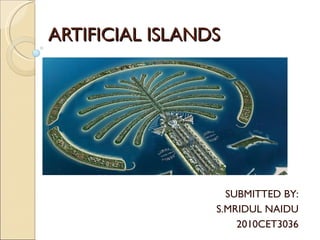
- 1. ARTIFICIAL ISLANDS SUBMITTED BY: S.MRIDUL NAIDU 2010CET3036
- 2. Methods of Creation 1)Expanding existing islets 2)Construction on existing reefs 3)Amalgamating several natural islets into a bigger island. 4)Construction on sea bed. 5)Land Reclamation 6)Oil Platforms Introduction An artificial or man-made island is an island or archipelago(group of islands) that has been constructed by people rather than formed by natural means.
- 6. Under the United Nations Convention on the Law of the Sea treaty (UNCLOS), artificial islands are not considered harbour works and are under the jurisdiction of the nearest coastal state if within 200 nautical miles (370 km) .Artificial islands are not considered islands for purposes of having their own territorial waters or exclusive economic zones, and only the coastal state may authorize their construction. However, on the high seas beyond national jurisdiction, any "state" may construct artificial islands . Political Status
- 11. CONSTRUCTION PROCESS DREDGING AND SOIL BED PREPERATION
- 12. PRECAST PILES CAST IN YARDS, LOADED ONTO BARGES AND PLACED AT SITE.
- 13. PILES DRIVEN, SOIL COMPACTED, SURROUNDING BUND CREATED, ARMOUR ROCKS PLACED , PLATFORM SLAB CASTED CONSTRUCTION STARTS.
- 22. PREPERATION OF ISLAND BED S.NO. PROCESS METHODS 1 SURVEY, INVESTIGATION AND CONTROLS ELECTRONIC SATELLITE NAVIGATION, SPAR BUOYS, ACOUSTIC TRANSPONDERS, CORING AND SAMPLING, GRAB SAMPLES, SPARKER SURVEY, SIDE-SCAN SONAR, ACOUSTIC IMAGING, FOUNDATION PENETROMETERS, VIDEO, SUBMERSIBLE AND DIVER INSPECTION 2 PLATFORM DERRIK BARGE, DRILL SHIP, SEMISUBMERSIBLE JACK-UP, GUYED TOWER, HEAVE COMPENSATORS 3 SEAFLOOR OBSTRUCTION REMOVAL DRAG-OFF WITH TRAWLERS, SHAPED CHARGES, ROV'S WITH MANIPULATORS, UNDERWATER BURNING, THERMIC LANCERS 4 DREDGING, REMOVAL OF SEDIMENTS TRAILER SUCTION HOPPER DREDGE, CUTTERHEAD HYDRAULIC DREDGE, GRAB DREDGE OR CLAMSHELL, CONTINOUS BUCKET LADDER DREDGE, SLACK LINE BUCKET DREDGE, PLOW, JETTING, PIPELINE BURIAL SLED, DEEP-SEA MINING DRAG EXCAVATOR, AIRLIFT, EDUCTORS, REMOTE-CONTROLLED SEAFLOOR DREDGE 5 DREDGING, REMOVAL OF HARD SEDIMENTS AND ROCKS HYDRAULIC BACKHOES, DIPPER DREDGES, POWER ACTIVATED CLAMSHELL BUCKETS, PLOWS, SHAPED CHARGES, BLASTING IN DRILLED HOLES, CHISELS, HYDRAULIC AND PNEUMATIC ROCK BREAKERS, DRIVEN SPUDS, CUTTERHEAD DREDGES, HIGH PRESSURE JETS 6 PLACEMENT OF UNDERWATER FILLS DIKES OF ROCKS OR CLAY BUNDS TO CONTAIN SAND, CONTROLLED UNDERWATER DEPOSITION, DUMP ENMASSE FROM HOPPER BARGES, TREMIE, BUCKET, SKIP, CHUTE OR LADDER 7 DENSIFICATION, CONSOLIDATION AND STRENGTHENING OF FILLS DEEP VIBRATION, SURFACE VIBRATION, DYNAMIC COMPACTION WITH DROPPED WEIGHTS, EXPLOSIVES OR AIRGUN, DEPOSITION IN MASS, PRESATURATION, SELECTION OF OPTIMUM GRADING
- 23. 8 CONSOLIDATION AND STRENGTHENING OF WEAK SOILS SAND PILES, VIBRATION, FREEZING, PRESURCHARGING, SURCHARGING WITH MEMBRANE AND DRAINAGE, SURCHARGING WITH STRUCTURE AND BALLAST, WICK AND SAND DRAINS, DRAINAGE WELLS, PERIPHERAL SURCHARGING, CEMENT INJECTION, CHEMICAL GROUTING, LIME INJECTION, DEEP CEMENT MIXING, ELECTRO-OSMOSIS 9 PREVENTION OF LIQUEFACTION DENSIFICATION, DRAINAGE WELLS, PERIPHERAL APRON OF GRADED ROCK 10 LEVELING OF SEAFLOOR OR EMBANKMENT HYDRAULIC DUSTPAN DREDGE WITH HEAVE COMPENSATOR SUSPENSION OF DREDGE HEAD, DRAGS, BOTTOM-SUPPORTED SCREED FRAME, SCREED FRAME FROM TLP OR HEAVE COMPENSATED PLATFORM, HORIZONTAL SCREW AUGUR 11 PROVISION OF UNIFORM SUPPORT UNDER BASE OF STRUCTURE UNDERBASE GROUTING, UNDERBASE SAND INJECTION OR SAND FLOW, TREMIE CONCRETE, GROUT INTRUDED AGGREGATE, MUD JACKING 12 EXCAVATION BENEATH STRUCTURE ARTICULATED DREDGE ARMS, AIRLIFT, JETS, EDUCTORS, DRILLS 13 SCOUR AND EROSION PROTECTION SACRIFICIAL FILL, ROCK, FILTER ROCK, FILTER FABRIC, ARTICULATED MATTRESSES, SANDBAGS, GROUT FILLED POROUS BAGS, SKIRTS ON STRUCTURES, APRONS AND FLOW CONTROLLED DEVICES AT BASE OF STRUCTURES, ARTIFICIAL SEAWEED, SAND ASPHALT AND ROCK ASPHALT BLANKETS, UNDERWATER CONCRETE SLABS 14 TURBIDITY SUPPRESSION BENTONITE-CEMENT SLURRIES, DISCHARGE OF FINE SAND BLANKET
- 24. DREDGING
- 25. Dredging Basics Dredging is the maritime transportation of natural materials from one part of the water environment to another by specialised dredging vessels. In a usual dredging cycle, self-propelled ,trailing suction ,hopper dredgers, barges and other ships spend the majority of their time sailing back and forth between excavation sites and placement sites, transporting materials between the port and the borrow site; sailing between borrow sites; and sailing from sites where material has been extracted to unloading or placement sites.
- 27. EXTERNAL CONDITIONS DURING CONSTRUCTION GROUP A : THOSE WHICH DETERMINE THE USE AND EFFICIENCY OF EQUIPMENT, BREIFLY SUMMARIZED UNDER THE HEADING OF WORKABILITY GROUP B: THOSE ARISING FROM A CHANGE IN THE HYDRAULICS AND MORPHOLOGY OF THE AREA, OCCURING AS A RESULT OF THE WORKS, THIS INFLUENCE CAN BE OF A TEMPORARY OR PERMANENT NATURE. GROUP C: THOSE ARISING FROM ENVIRONMENTAL CONSIDERATIONS, ALSO THIS EFFECT CAN BE OF A TEMPORARY OR PERMANENT NATURE.
- 28. Common dredging methods : Suction Dredging : Sand will be dredged by putting the suction tube deep ( > 10 m) into the sand layer. Under the influence of gravity forces the sand departs from the slope and flows downward in the direction of the suction mouth. Cutter Suction Dredging : With cutter suction dredging the suction tube is provided with a rotating cutter head. The swing movement is initiated by the means of a forward-side-winch wires directly behind the cutter head. A spud pole positioned on the ships aft functions as centre of the swing movement.
- 31. Trailing suction dredging : A draghead attached to a suction pipe is trailed over the bottom of the seafloor. Due to erosive forces at the narrow opening between the draghead and the bottom and the application of blades in the draghead results in the formation of a sand water mixture, this mixture in pumped in the hopper and the sand settles whereas the water overflows. Cutter Dredging : For less permeable sand the face formation will deliver a small contribution to the production. In this case the soil has to be retrieved with the cutter head. In less permeable sand, large cutting forces cause significant wear and tear to the teeth of the cutting head.
- 34. CRITERIA FOR DREDGER SIZE: 1. Volume of material to be dredged. 2. Time allowed to complete the project. Days, weeks and months. 3. Hours that you will work. 1 shift, 2 shifts or 3 shifts? 4. Type of material to be dredged. Fine sand, medium sand, large sand, small gravel, large gravel, silt, clay, cobbles 3 to 10, boulders +10 inches [254mm]. 5. Dredging sediments or undisturbed material. Undisturbed material is much more difficult to dredge. 6. Horizontal pumping distance. 7. Vertical pumping distance called static head. vertical distance from the water surface to the discharge point. 9. Maximum digging depth. Distance from the water surface to the lowest point of dredging. DREDGES ARE AVAILABLE IN SIZES VARYING FROM A FEW METRE LONG BARGES TO FEW HUNDRED METRE LONG VESSLES
- 35. Factors in selection of Cutter Suction Dredger • Kind of soils and operation area • Dredging depth, capacities • Degree of self-sufficiency, self-propelled or stationary. • If self-propelled: which cutter ladder position (bow or stern oriented) • Seagoing dredging capability. • Type and stroke of spud carriage (flexibility required) • Spud handling and hoisting system(s). • Cutter type, diameter, speed, power. • Pump characteristics. • Requirements related to noise and vibrations (incl. construction fatigue) • Degree of automation.
- 41. Dredge pump capacity -required flow rate and head -discharge pipeline length(differ for pumping ashore and barge loading) -density of the mixture -soil characteristics -suction mouth performance. Therefore a lot of scenarios have to be calculated to find an optimum design point of each pump.
- 43. Spud carriage The application of a spud carriage is common practise for large CSD’s. This increases the efficiency of the dredger significantly. The larger the stroke of the carriage the more swings can be made without spud repositioning and consequently the higher the efficiency of the dredger. Automation Large cutter dredgers are complex dredgers with complex operations. Therefore process automation and monitoring instrumentation are relevant because they will increase the efficiency of the dredger. Automation can be executed to a lot of levels, which depends on the Owner’s philosophy and the cost and skills of personnel.
- 44. Increased main dimensions of the dredger result in significant lower movements of the vessel in waves.
- 47. PUMPING THE DREDGED MATERIAL :
- 48. The material dredged from the seafloor is placed either by the dredger itself by pumps on deck, or by pipelines or barges.
- 49. COMPARISION BETWEEN SAND PLACEMENT MECHANISMS.
- 51. CONCRETING
- 54. 5) REINFORCING STEEL: Plain Bars, deformed bars, welded fabrics may be used provided details of size, mechanical properties and bond properties supplied by manufacturer. 6) SHEATHING: Rigid or semi-rigid water-tight metal sheathing should be used. Should be spliced with tightly fitting sleeves and the joints bound with waterproof tape. 7) GROUT : Usually OPC cement, aggregates if used in large ducts should consist of siliceous granules, finely ground limestone, trass, pozzolan or fine sand ; admixtures to be used after testing, sea water should not be used.
- 56. SHIP MOUNTED CONCRETE PLACEMENT BOOM HOISTS ETC, ON GROUND OR BARGE/SHIP MOUNTED.
- 57. OTHER PROCESSES
- 59. BREAKWATER IMAGE : PALM JUMERIAH , DUBAI
- 62. SKETCH SHOWING THE VIBRO-COMPACTION PROCESS
- 64. FAMOUS ARTIFICIAL ISLANDS THE WORLD- DUBAI PALM JUMERIAH - DUBAI KANSAI AIRPORT, JAPAN
- 65. BURJ AL ARAB HOTEL, DUBAI