Understanding Discord NSFW Servers A Guide for Responsible Users.pdf
Getting Started With Arduino_Tutorial
1. Getting Started with Arduino
Introduction to Physical Computing
Edited by Alvaro Soto-Fernandez
The City University of New York
Architectural Technology Dept.
2. Getting Started with Arduino
2
Introduction
Arduino is an open-source physical computing
platform for developing interactive devices that
are able to sense the environment using sensors (
electronic components that convert real-world data
into electrical signals), and interact with the world
using actuators, electronic components that can
convert electric signals into a physical action. Arduino
is based on a simple micro-controller board, and a
IDE (development environment) for writing software
that controls the behavior of the board. Arduino
projects can be standalone, or they can communicate
with other software running on your computer (e.g.
Grasshopper, Processing, Flash, etc). The open-
source (and cross-platform) IDE can be downloaded
for free at www.arduino.cc.
3. Getting Started with Arduino
3
The Hardware
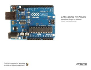
The Arduino board Fig. 1 is a small microcontroller
board (circuit) manufactured by the Arduino
Corporation, that contains a whole computer on a
small chip, the ATmega168, which is less powerful
than new computers, but cheaper and very useful for
prototyping and to build interactive devices.
The Arduino Corporation is not alone in the
development of user-friendly microcontroller
platforms. Here are some reasons why you might
choose Arduino over its “competitors”:
1. Open-source - (you can download the circuit
diagram, buy all the components, and make your
own).
2. Cross-platform (works well on both PC and
Macintosh)
3. Inexpensive (around $30)
4. Already established techniques of interfacing
with popular software environments.
5. A large community of users (great technical
support).
Fig. 1 -Arduino prototyping board
4. Getting Started with Arduino
4
The Hardware
The Arduino team have placed on the board all the
components (resistors, capacitors, regulators, etc_
that are required for this microcontroller to work
properly and to communicate with other computers.
The most often used elements of this hardware
interface are highlighted in Fig 2.
• DC Power In: This is a plug that accepts a
2.1mm barrel with a positive tip (center positive).
The Arduino board will happily accept any voltage
between 7-12 and a current between 100-
500mA. 9V batteries (with the appropriate barrel
adaptor) are acceptable.
• USB: Universal Serial Bus is used to communicate
in both directions between Arduino and a
computer. When in use, the USB port can also
power the Arduino board, eliminating the need for
an external DC power supply.
• Power Out: When powered (either by DC supply
or USB), the Arduino board provides regulated
power outputs for the rest of your project (5v,
3.3v, and GND – 0 potential).
• Atmel Chip: This chip is the brain of the Arduino
board. It contains the Arduino “bootloader”,
which is essentially a program that runs on the
chip that allows you to upload and run custom
programs written by you to the chip. When you
upload programs to the chip using the Arduino
IDE, you are replacing your previously uploaded
program and not the bootloader. The bootloader
is “permanently burned” to the chip’s memory
(not really, but it takes more effort to remove the
bootloader if you did want a completely blanks
chip for some reason).
Fig. 2 -Hardware Interface
5. Getting Started with Arduino
5
The Hardware
• Analog Pins: The Arduino Uno board has six
analog pins for measuring continuous data from
the outside world. By default, each pin measures
voltage from 0v-5v and converts that voltage into
a range of 0-1023 (10-bit resolution). Each pin is
readable by your custom program uploaded onto
the Atmel chip (if you instruct the program to do
so).
• Digital Pins: The Arduino Uno board has 14 digital
pins that can be both read and written to. Digital
pins measure voltage from 0v-5v but in contrast
to analog pins, convert that measurement into a
binary of either HIGH or LOW. High being 5v and
low being 0v (or GROUND). Several specific digital
pins can multipurpose for specialized tasks like
serial communication (TX & RX) and Pulse Width
Modulation (PWM).
• Reset Button: This is a simple push button that
when pressed tells your Arduino program to run
again from the beginning (it does not erase the
Atmel chip or your program).
6. Getting Started with Arduino
6
The Software
Interface
The IDE (Integrated Development Environment) is an
open-source program running on your computer that
allows you to write sketches for the Arduino board
in a simple language modeled after the Processing
(www.processing.org) language. With this technology
the Arduino replaces the need for hard wiring circuits
from scratch with a software program which is easier
to use than other programing languages and easier to
modify than hardware alone. After you have installed
(for detailed instruction on installation depending on
your operating system, go here: http://arduino.cc/en/
Guide/HomePage ) and opened the Arduino IDE, Fig.
3 is what you will see.
The Arduino IDE interface is very simple, there are
four main parts (shown in Fig. 4):
• Text Editor: This is the heart of the Arduino IDE
and where you write your programs (Arduino calls
them “sketches”).
• Console: This is where the IDE outputs
information regarding your sketch (errors, upload
status)
• Tool Bar: These icons provide a shortcut to the
most often used operations. From left to right they
are “Verify (check sketch for errors)”, “Upload”,
“New”, “Open”, “Save”, and “Serial Monitor.”
• Menu Bar: The menu bar gives you access to
all of the IDE’s functionality including some very
important settings that should be adjusted before
anything else.
Fig. 3 -Arduino IDE Fig. 4 -Four main parts of Arduino IDE
Menu Bar
Tool Bar
Text Editor
Console
7. Getting Started with Arduino
7
The Software
Setting up the Arduino Board
Once you have downloaded and installed the Arduino
IDE, before uploading any sketch, make sure the
IDE is setup to recognize the type of Arduino board
you are planing to upload to. There are several types
of Arduino boards that differ in size, circuitry, chip
memory, number of I/O (In/Out) pins and add-on
capabilities (e.g. Ethernet connectivity). Arduino UNO
js the most recent simplify version of the board.
Next, in order for the IDE to communicate with your
board, you also have to select the correct Serial Port
that your board is installed on. Select your Arduino
board from Tools > Board (ad shown in Fig, 5), and
the line of communication on which it is installed from
Tools > Serial Port (select the port that begins with /
dev/cu.usbserial-).
Now you can Start programing.
Fig. 5 -Setting up the Arduino Board
8. Getting Started with Arduino
8
The Software
Setting up the Sketchbook Folder
However, before you write your first sketch, you should
know the location of your “Sketchbook.” Each sketch
you write is automatically saved in a folder of the
same name, and these sketch folders as a collection
are stored in another folder called a sketchbook. The
location of your sketchbook can be set in your Arduino
preferences in the menu bar under File > Preferences
(as shown in Fig. 6).
Now you can quickly access any sketch you have
written in the menu bar under File > Sketchbook.
Fig. 6 -Setting up the Sketchbook Folder
9. Getting Started with Arduino
9
Run Your First Sketch
Blinking LED
The LED blinking sketch, found in FIle > Examples
> Basic > Blink, is the first program you should run
to test whether your Arduino board is working and is
configured correctly. This sketch is also very useful for
starters to learn how to program the microcontroller. A
light-emitting diode (LED), is an electronic component
more efficient than a light bulb and requires lower
voltages to operate.
The Arduino board comes with an LED preinstalled,
you can also add your own LED to pin 13 and ground.
FIg. 7
Fig. 7 -LED to Pin 13