Ultrasound machine
•Télécharger en tant que PPT, PDF•
28 j'aime•23,991 vues

Ultrasound machine presentation with circuits and working.

Recommandé
Contenu connexe
Tendances
Tendances (20)
En vedette
En vedette (20)
Similaire à Ultrasound machine
Similaire à Ultrasound machine (20)
Dernier
Dernier (20)
Ultrasound machine
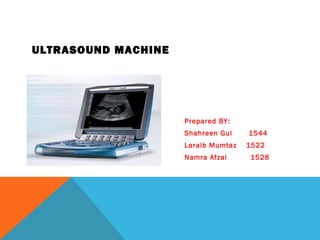
- 1. ULTRASOUND MACHINE Prepared BY: Shahreen Gul 1544 Laraib Mumtaz 1522 Namra Afzal 1528
- 2. MECHANICAL ASSEMBLY. • Transducer: Probe Pulse Control • CPU (Central Processing Unit) • Key Board • Display • Storage device • Printer
- 4. ELECTRONIC CIRCUIT OF MACHINE
- 6. ULTRASOUND PHYSICS: • What is sound/ultrasound? • How is ultrasound produced • Transducers - properties
- 7. SOUND: • Sound is a mechanical, longitudinal wave that travels in a straight line
- 8. WHAT IS ULTRASOUND? • Ultrasound is a mechanical, longitudinal wave with a frequency exceeding the upper limit of human hearing, which is 20,000 Hz or 20 kHz. Medical Ultrasound 2MHz to 16MHz
- 9. Human HairHuman Hair SingleSingle CrystalCrystal Microscopic view of scanhead
- 10. TRANSDUCER DESIGN: Size, design and frequency depend upon the examination
- 12. ULTRASOUND PRODUCTION: • Transducer contains piezoelectric elements/crystals which produce the ultrasound pulses
- 13. THE RETURNING ECHO: • Reflected echoes return to the scanhead where the piezoelectric elements convert the ultrasound wave back into an electrical signal • The electrical signal is then processed by the ultrasound system
- 14. PIEZOELECTRIC MATERIAL • AC applied to a piezoelectric crystal causes it to expand and contract – generating ultrasound.
- 15. PIEZOELECTRIC CRYSTALS • The thickness of the crystal determines the frequency of the scanhead Low Frequency 3 MHz High Frequency 10 MHz
- 16. FREQUENCY VS. RESOLUTION: The frequency also affects the QUALITY of the ultrasound image • The HIGHER the frequency, the BETTER the resolution • The LOWER the frequency, the LESS the resolution
- 17. FREQUENCY VS. RESOLUTION • A 12 MHz transducer has very good resolution, but cannot penetrate very deep into the body • A 3 MHz transducer can penetrate deep into the body, but the resolution is not as good as the 12 MHz
- 19. WORKING
- 20. INTERACTIONS OF ULTRASOUND WITH TISSUE Reflection Refraction Transmission Attenuation
- 21. IMAGE FORMATION Electrical signal produces ‘dots’ on the screen Brightness of the dots is proportional to the strength of the returning echoes
- 22. INTERACTIONS OF ULTRASOUND WITH TISSUE • Reflection • The ultrasound reflects off tissue and returns to the transducer, the amount of reflection. • The ultrasound image is formed from reflected echoes transducertransducer
- 23. ATTENUATION & GAIN Sound is attenuated by tissue More tissue to penetrate = more attenuation of signal Compensate by adjusting gain based on depth.
- 24. ULTRASOUND GAIN • Gain controls • receiver gain only does NOT change power output • Increase gain = brighter • Decrease gain = darker
- 25. BALANCED GAIN Gain settings are important to obtaining adequate images. balanced
- 26. REFLECTED ECHO’S Strong Reflections = White dots Diaphragm, tendons, bone
- 27. REFLECTED ECHO’S No Reflections = Black dots • Fluid within a cyst, urine, blood • Echofree.
- 28. TYPES • 3D • Doppler ultrasound
- 29. USES • Gynacology • Cardiology • Urology • Tumour detection
- 30. DISADVANTAGE • Heat development • Cavity formmation
Notes de l'éditeur
- Transducer probe - probe that sends and receives the sound waves Central processing unit (CPU) - computer that does all of the calculations and contains the electrical power supplies for itself and the transducer probe Transducer pulse controls - changes the amplitude, frequency and duration of the pulses emitted from the transducer probe Display - displays the image from the ultrasound data processed by the CPU Keyboard/cursor - inputs data and takes measurements from the display Disk storage device (hard, floppy, CD) - stores the acquired images Printer - prints the image from the displayed data
- Ultrasound is an oscillating sound pressure wave with a frequency greater than the upper limit of the human Ultrasound is thus not separated from 'normal' (audible) sound by differences in physical properties, only by the fact that humans cannot hear it. Ultrasonic devices are used to detect objects and measure distances. Ultrasonic imaging (sonography) is used in both veterinary medicine and human medicine. In the nondestructive testing of products and structures, ultrasound is used to detect invisible flaws. Industrially, ultrasound is used for cleaning and for mixing, and to accelerate chemical processes. Animals such as bats and porpoises use ultrasound for locating prey and obstacles aring range.
- Pulse generator + oscillator +time The 555 timer IC is an integrated circuit (chip) used in a variety of timer, pulse generation, and oscillator applications. The 555 can be used to provide time delays, as an oscillator, and as a flip-flop element
- Sound requires a medium through which to travel oscillations/sec = frequency - expressed in Hertz (Hz)
- Produced by passing an electrical current through a piezoelectrical crystal
- These elements convert electrical energy into a mechanical ultrasound wave
- The ultrasonic receiver circuit uses an ultrasonic receiver transducer to sense ultrasonic signals. It also uses a two-stage amplifier, a rectifier stage, and an operational amplifier in inverting mode. Output of op-amp is connected to a relay through a complimentary relay driver stage. A 9-volt battery eliminator can be used for receiver circuit, if required. When switch S1 of transmitter is pressed, it generates ultrasonic sound. The sound is received by ultrasonic receiver transducer. It converts it to electrical variations of the same frequency. These signals are amplified by transistors T3 and T4. The amplified signals are then rectified and filtered. The filtered DC voltage is given to inverting pin of op-amp IC2. The non- inverting pin of IC2 is connected to a variable DC voltage via preset VR2 which determines the threshold value of ultrasonic signal received by receiver for operation of relay RL1. The inverted output of IC2 is used to bias transistor T5. When transistor T5 conducts, it supplies base bias to transistor T6. When transistor T6 conducts, it actuates the relay. The relay can be used to control any electrical or electronic equipment. Important hints: 1. Frequency of ultrasonic sound generated can be varied from 40 to 50 kHz range by adjusting VR1. Adjust it for maximum performance. 2. Ultrasonic sounds are highly directional. So when you are operating the switch the ultrasonic transmitter transducer of transmitter should be placed towards ultrasonic receiver transducer of receiver circuit for proper functioning. 3. Use a 9-volt PP3 battery for transmitter. The receiver can be powered from a battery eliminator and is always kept in switched on position. 4. For latch facility use a DPDT relay if you want to switch on and switch off the load. A flip-flop can be inserted between IC2 and relay. If you want only an ‘ON-time delay’ use a 555 only at output of IC2. The relay will be energised for the required period determined by the timing components of 555 monostable multivibrator. 5. Ultrasonic waves are emitted by many natural sources. Therefore, sometimes, the circuit might get falsely triggered, espically when a flip-flop is used with the circuit, and there is no remedy for that.
- Reflection The ultrasound reflects off tissue and returns to the transducer, the amount of reflection depends on differences in acoustic impedance The ultrasound image is formed from reflected echoes
- Sound is attenuated as it goes deeper into the body Location of the dots is determined by travel time. The velocity in tissue is assumed constant at 1540m/sec Distance = Velocity Time
- Attenuation Defined - the deeper the wave travels in the body, the weaker it becomes -3 processes: reflection, absorption, refraction Air (lung)> bone > muscle > soft tissue >blood > water