1. DMMs For
Every Application
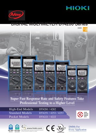
Super Fast Response Rate and Safety Features Take
Professional Testing to a Higher Level
High-End Models DT4281 / 4282
Pocket Models DT4221 / 4222
Standard Models DT4251 / 4252 / 4253
DIGITAL MULTIMETER DT4200 Series
DMM
2. 2
DT4280/4250/4220 Series Features
The world’s fastest DMM engine
Nearly 0.6 s measurement response
In striving to offer the world’s fastest
measurement response in a DMM, the custom
ASIC is developed in-house at Hioki, allowing
us to embody the concentration of our
technological strengths.
Get a stable reading in about half a second
from probe contact to display.
See for yourself how fast it really is with
the DT4250 and DT4220 Series.
To Be The
World’s Fastest
Bright Backlight
The super bright LED backlight is
indispensable in dark locations to clearly
capture the measured values.
(Red LED backlight available only in the DT4280 series)
Shock and Dust Resistant
Protective rubber edges around the DMM
endure drop from 1 meter onto a concrete
floor and a precise design shields against dusty
environments.
Operator Safety
Safety is our priority. Terminal shutters in
the DT4280 Series and other safety features
assist in preventing accidents to the operator
and damage to the instrument.
Absolutely Reliable True RMS
Signal measured with
true rms method
Measures distorted
current values The True RMS method provides the best accuracy.
Signal measured with
averaging method
IP42
The DT4280 series is rated IP40.
3. 3
15 times better noise immunity
over former models
Useable in noisy environments
630 Hz low-pass filter cuts harmonics -
ideal for measuring inverter systems.
DT4281
Safety First
Safety First
General Purpose
General Purpose
Specialized applications
Safety First
General Purpose
DT4282
Standard Choose from 3 models according to your measurement situation
Pocket Quick, simple and safe testing in a palm-sized unit
n CAT III1000V/ CAT IV600V
n CAT III1000V/ CAT IV600V
n CAT III600V/ CAT IV 300V
clamp
DT4221/4222 Measurement Parameters
Frequency ContinuityDCvoltage ACvoltage
DT4251/4252/4253 Measurement Parameters
Resistance Capacitance Frequency DiodeContinuityDCvoltage ACvoltage
DT4251
Clamp
Voltage
Detector
DT4221
Voltage
Detector
DT4222
Capacitance Diode Resistance
DT4253
ClampRangeTemperature
DT4252
DCA ACA
High
precision
mV range
DT4281/4282 Measurement Parameters
Range Resistance Capacitance Frequency Temperature
DiodeContinuity
DCvoltage ACvoltage DCV+ACV
High accuracy, additional function enhancements, broad range of measurement itemsHigh-End
Requires optional DT4900-01 Communication Package
Requires optional DT4900-01 Communication Package
Noise suppression with 100/500 Hz low-pass filter
Runs on one AAA battery, for simple replacement
Effortless operation with
probe storage clips behind the instrument
Noise suppression with 100/500 Hz low-pass filter
Dual-value and bar graph displays
Internal memory stores up to 400 data points
Red display warns of over-range
Transfer data to a PC
Transfer data to a PC
For electrical work and power line applications
For electrical work and power line applications
For laboratories and R&D
For laboratories and R&D
Instrumentation,airconditioningandgasequipment
For electrical work and power line applications
For laboratories and electrical testing
No ‘A’ terminal
Includes clamp sensor connection terminals
The current terminal is intentionally
excluded, for those who need the extra
safety of a current measurement clamp.
For those with diverse measurement needs
Resistance
Capacitance
Includes diode check
For those with diverse measurement needs
High precision 600mV range
6A and 10A ranges
For those with diverse measurement needs
6A and 10A ranges
Includes conductance measurement
No ‘A’ terminal
Includes clamp sensor connection terminals
and voltage detector
For those who need the extra safety
60μA to 60mA range
Includes temperature measurement
For HVAC, instrumentation and
temperature testing
No current or resistance functions
Auto DC/AC detection
Includes voltage detector
Ideal for safe voltage measurements
Red LED indicates over-range and
aids in continuity checking
ConductanceDCA ACA
4. 4
DT4281 DT4282 DT4251 DT4252 DT4253 DT4221 DT4222
Basic Characteristics
True RMS Yes Yes Yes
DCV basic accuracy ±0.025 %rdg. ±2 dgt. ±0.3 %rdg. ±5 dgt. ±0.5 %rdg. ±5 dgt.
Measurement items (Typical ranges are indicated; may not reflect maximum or minimum measurable signal)
DC voltage 60mV to 1000V 600mV to 1000V 600mV to 600V
AC voltage 60mV to 1000V 6V to 1000V 6V to 600V
DCV + ACV 6V to 1000V n/a n/a
DCA current 600μA to 600mA 600μA to 10A n/a 6A to 10A 60μA to 60mA n/a
ACA current 600μA to 600mA 600μA to 10A n/a 6A to 10A n/a n/a
AC clamp 10A to 1000A n/a 10A to 1000A n/a 10A to 1000A n/a
Resistance 60Ω to 600MΩ 600Ω to 60MΩ n/a 600Ω to 60MΩ
Temperature -40°C to 800°C n/a n/a -40°C to 400°C n/a
Capacitance 1nF to 100mF 1μF to 10mF n/a 1μF to 10mF
Frequency 99Hz to 500kHz 99Hz to 99kHz 99Hz to 9.9kHz
Continuity check Yes Yes Yes
Diode check Yes Yes n/a Yes
Conductance n/a Yes n/a n/a
Voltage detection n/a Yes n/a n/a Yes n/a
Additional Functions
AUTO AC/DCV n/a Yes n/a Yes Yes n/a
Peak measurement DC/AC n/a n/a
Low-pass filter
Analog filter Digital filter Digital filter
Cut-off : 630 Hz Pass-band : 100Hz/500Hz Pass-band : 100Hz/500Hz
Display update setting Yes n/a n/a
Hold display value AUTO / MANUAL AUTO / MANUAL MANUAL
Max/Min value display Yes Yes n/a
Relative display Yes Yes Yes
Decibel conversion Yes n/a n/a
Percentage conversion display Yes n/a n/a Yes n/a
Data storage
Capacity Max 400 data n/a n/a
USB communication*1 Yes Yes n/a
Operating time
Continuous operating time Approx. 100 hours*2 Approx. 130 hours Approx. 40 hours
Power supply Alkaline (LR6) battery ×4 / Manganese(R6P) battery ×4 Alkaline (LR03) battery ×4 Alkaline (LR03) battery ×1
Display
Back light Yes Yes Yes
Dual display Yes Yes n/a
Bar graph display n/a Yes Yes
Safety
Safety standard categories CAT III1000V/ CAT IV600V CAT III1000V/ CAT IV600V CAT III600V/ CAT IV300V
Mis-insertion prevention shutters Yes n/a n/a
DT4200 Series Basic Comparison
Glossary
*1. Requires optional DT4900-01 Communication Package
*2. When using four AA alkaline batteries
Auto AC/DCV Automatically detects and measures AC and DC voltage.
Peak measurement After starting PEAK value measurement, check maximum and minimum instantaneous voltage and current values.
Low-pass filter Cuts high frequency content to provide stable numerical values for measurement.
Display update setting Reduces the display value update rate to stabilize measurements.
Hold display value Manual: press the button to freeze the display. Auto: the display freezes automatically when the measurement value is stable.
Max/Min value display Pressing the MAX/MIN button displays the maximum and minimum displayed measurement values.
Relative display Pressing the REL button displays subsequent measurements as values relative to that displayed when the button was pressed.
Decibel conversion Displays AC voltage measurements converted to decibel values (dbm/dbv)
Percentage conversion display Displays 4 to 20 mA (or 0 to 20 mA) signals converted to 0 to 100% values. For the DT4253, only 4 to 20 mA.
5. 5
High-end Standard Pocket
Usage / Model DT4281 DT4282 DT4251 DT4252 DT4253 DT4221 DT4222
No current or resistance measurements 4
No current measurements 4 4 4
High current measurements with clamp 4 4 4
mA measurements for instrumentation 4 4
Need 6A and 10A 4 4
Mis-insertion prevention shutters 4 4
Current Measurement Based Selection Guide
197mm (7.76 inch) 174mm (6.85 inch) 149mm (5.87 inch)
93mm
(3.66 inch)
84mm
(3.31 inch)
72mm
(2.83 inch)
53mm
(2.09 inch)
52mm
(2.05 inch)
38mm
(1.50 inch)
High-end
Standard
Pocket
Size Comparison
Hioki’s new digital multimeter series include models with no directly accessible current measuring terminals.
These models reflect our mission to provide the highest level of safety in a DMM.
Why are there no current measurement terminals on some of the models?
SAFE
NOT
SAFE
High input impedance measurements Measures voltage
Measures currentLow input impedance measurementsCurrent measurement ranges
Voltage measurement ranges
Voltage is measured by mistakeLow input impedance measurementsCurrent measurement ranges
Accidentally measuring voltage with the low input impedance of a current measurement
range may cause inadvertent breaker trip, short circuits, or fire hazards.
OFF
DMMs that minimize the risk factor of a current measurement terminal.
Voltage testing is the primary objective, with current testing using a clamp on sensor.
Solution
Target Applications
Quick Reference
6. 6
DT4281/DT4282
Avoid incorrect function settings and terminal connections
When the rotary selector is turned to a current measurement position,
only the corresponding current measurement terminals are accessible.
To improve the efficiency of UPS maintenance,battery cell volt-
age can be stored on the spot. Save up to 400 data points.
Using the optional DT4900-01 Communication Package, internally stored data can be
displayed in graphs and stored in files at specified intervals.
When connected to a PC while measuring, data can be displayed and stored in the PC
in real time. Data saved in internal memory is stored in text format on the PC.
n Display
n Hazard Prevention
n Data Management
Input over 1000 V AC or
DC is indicated by a red
screen and a clear beep.
Read measurements from any angle.
White backlight ensures readable
measurements even in dark
locations.
Red screen indicates short
circuits. Visual confirmation
even in noisy worksites.
Wide viewing angle display
Just press the MEM key to store data internally
Terminal incorrect lead connections
Easy to see even in dark worksites Continuity check
Capturing measurement data
Over-range input indication
Only ‘A’ and COM terminals are accessible
Only ‘µA mA’ and COM terminals are accessible
When the ‘A’ range is selected*1
*1. The ‘A’ range is only on the DT4282.
When ‘µA mA’ range is selected
MEM
n Handy Measurement Features
Optimized for inverter system measurements
Ideal for checking ripple voltage in DC supply systems
Low-pass filter 630Hz
Peak measurement function & DC+AC voltage measurement
Filter OFF Filter ON
Capture ripple voltage
components on
direct current signals.
Input
waveform
114.1V 85.9V 100V
Typical waveform componentTypical waveform +harmonic components
0V 0V
For inverter secondary output
voltage measurements, harmonic
contents are cut so that the
fundamental waveform can be
measured.
DC+AC V range
+PEAK measurement ▶114.10V
▶ 85.90V-PEAK measurement
▶100.49VDC+AC measurement*
*DC+AC = (AC)+(DC)
2 2
√
Select the 600.00 µA DC
range for burner flame
current measurement.
Burner
Flame Rod
Insulator
Control
Board
Inspect burner systems When a hand cannot be usedDCµA range AUTO Hold display value
The display freezes
automatically
when the measurement
value is stable.
7. 7
DC Voltage
Range Accuracy Input Impedance
60.000 mV ±0.2 %rdg. ±25 dgt.
1GΩ or more
600.00 mV ±0.025 %rdg. ±5 dgt.
6.0000 V
±0.025 %rdg. ±2 dgt.
11.0MΩ
60.000 V 10.3MΩ
600.00 V
±0.03 %rdg. ±2 dgt. 10.2MΩ
1000.0 V
AC Voltage
Range
Accuracy
20 to 45Hz 45 to 65Hz 65 to 1kHz 1k to 10kHz 10k to 20kHz 20k to 100kHz
60.000 mV ±1.3 %rdg.
±60 dgt.
±0.4 %rdg.
±40 dgt.
±0.6 %rdg.
±40 dgt.
±0.9 %rdg.
±40 dgt.
±1.5 %rdg.
±40 dgt.
±20 %rdg. ±80 dgt.
600.00 mV ±8 %rdg. ±80 dgt.
6.0000 V
±1 %rdg.
±60 dgt.
±0.2 %rdg.
±25 dgt.
±0.3 %rdg.
±25 dgt.
±0.4 %rdg.
±25 dgt.
±0.7 %rdg.
±40 dgt.
±3.5 %rdg.
±40 dgt.
60.000 V
Undefined600.00 V
Undefined Undefined
1000.0 V
DCV + ACV Measurement
Range
Accuracy
20 to 45Hz 45 to 65Hz 65 to 1kHz 1k to 10kHz 10k to 20kHz 20k to 100kHz
6.0000 V
±1.2 %rdg.
±65 dgt.
±0.3 %rdg.
±30 dgt.
±0.4 %rdg.
±30 dgt.
±0.4 %rdg.
±30 dgt.
±1.5 %rdg.
±45 dgt.
±3.5 %rdg.
±125 dgt.
60.000 V
Undefined
600.00 V
Undefined Undefined
1000.0 V
±0.4 %rdg.
±45 dgt.
Input impedance 1MΩ ± 4 %//100pF or less
Crest factor 3 or less (1.5 or less for the 1000.0V range)
Accuracy
specification range
5% or more of each range
With the filter ON, accuracy is defined only for frequencies
100Hz or less. Furthermore, 2% rdg. is added
DCA Measurement 6A, 10A range : DT4282 only
Range Accuracy / Display update : SLOW Accuracy / Display update : NORMAL Shunt Resistance
600.00 μA
±0.05 %rdg. ±5 dgt.
±0.05 %rdg. ±25 dgt.
101 Ω
6000.0 μA ±0.05 %rdg. ±5 dgt.
60.000 mA ±0.15 %rdg. ±25 dgt.
1 Ω
600.00 mA ±0.15 %rdg. ±5 dgt. ±0.15 %rdg. ±5 dgt.
6.0000 A
±0.2 %rdg. ±5 dgt.
±0.2 %rdg. ±25 dgt.
10m Ω
10.000 A ±0.2 %rdg. ±5 dgt.
ACA Measurement 6A, 10A range : DT4282 only
Range
Accuracy
20 to 45Hz 45 to 65Hz 65 to 1kHz 1k to 10kHz 10k to 20kHz
600.00 μA
±1.0 %rdg.
±20 dgt.
±0.6 %rdg.
±20 dgt.
±0.6 %rdg.
±20 dgt.
±2 %rdg.
±20 dgt.
±4 %rdg.
±20 dgt.
6000.0 μA
±1.0 %rdg.
±5 dgt.
±0.6 %rdg.
±5 dgt.
±0.6 %rdg.
±5 dgt.
±2 %rdg.
±5 dgt.
±4 %rdg.
±5 dgt.
60.000 mA
±1.0 %rdg.
±20 dgt.
±0.6 %rdg.
±20 dgt.
±0.6 %rdg.
±20 dgt.
±1 %rdg.
±20 dgt.
±2 %rdg.
±20 dgt.
600.00 mA
±1.0 %rdg.
±5 dgt.
±0.6 %rdg.
±5 dgt.
±0.6 %rdg.
±5 dgt.
±1.5 %rdg.
±10 dgt.
Undefined
6.0000 A Undefined
±0.8 %rdg.
±20 dgt.
±0.8 %rdg.
±20 dgt.
Undefined Undefined
10.000 A Undefined
±0.8 %rdg.
±5 dgt.
±0.8 %rdg.
±5 dgt.
Undefined Undefined
Shunt resistance μA Range 101Ω/ mA Range 1Ω/ A Range 10mΩ
Crest factor 3 or less (Note that it applies to 1/2 of the range.)
Accuracy specification range Accuracy is not defined for measurements below 5% of range
Continuity Check
Range Accuracy Measurement Current Open-terminal Voltage
600.0 Ω ±0.5 %rdg. ±5 dgt. 640 μA ±10% 2.5 V DC or less
Continuity threshold 20Ω (default) /50Ω/ 100Ω/ 500Ω
Capacitance Measurement
Range Accuracy Measurement Current Open-circuit Voltage
1.000 nF ±1.0 %rdg. ±20 dgt.
32 μA ±10% DC2.5 V or less
10.00 nF
±1.0 %rdg. ±5 dgt.100.0 nF
1.000 μF
10.00 μF
±2.0 %rdg. ±5 dgt.
680 μA ±20%
DC3.1 V or less
100.0 μF
1.000 mF
DC2.1 V or less10.00 mF
100.0 mF ±2.0 %rdg. ±20 dgt.
Resistance Measurement
Range Accuracy Measurement Current Open-terminal Voltage
60.000 Ω ±0.3 %rdg. ±20 dgt.
640 μA ±10%
DC2.5 V or less
600.00 Ω ±0.03 %rdg. ±10 dgt.
6.0000 kΩ
±0.03 %rdg. ±2 dgt.
96 μA ±10%
60.000 kΩ 9.3 μA ±10%
600.00 kΩ 0.96 μA ±10%
6.0000 MΩ ±0.15 %rdg. ±4 dgt.
96 nA ±10%
60.00 MΩ ±1.5 %rdg. ±10 dgt.
600.0 MΩ
±3.0 %rdg. ±20 dgt.
±8.0 %rdg. ±20 dgt.
AC Clamp (AC Current) DT4281 only
Range
Accuracy
40 to 65Hz 65 to 1kHz
10.00 A ±0.6 %rdg. ±2 dgt. ±0.9 %rdg. ±2 dgt.
20.00 A ±0.6 %rdg. ±4 dgt. ±0.9 %rdg. ±4 dgt.
50.00 A ±0.6 %rdg. ±10 dgt. ±0.9 %rdg. ±10 dgt.
100.0 A ±0.6 %rdg. ±2 dgt. ±0.9 %rdg. ±2 dgt.
200.0 A ±0.6 %rdg. ±4 dgt. ±0.9 %rdg. ±4 dgt.
500.0 A ±0.6 %rdg. ±10 dgt. ±0.9 %rdg. ±10 dgt.
1000 A ±0.6 %rdg. ±2 dgt. ±0.9 %rdg. ±2 dgt.
The optional 9010-50, 9018-50, or 9132-50 CLAMP ON PROBE is used.
Accuracy does not include the error of the clamp-on probe.
Crest factor 3 or less
Accuracy is not defined for measurements below 15% of range
Conductance (nS) DT4282 only
Range Accuracy Measurement Current Open-circuit Voltage
600.00 nS ±1.5 %rdg. ±10 dgt. 96 nA ±10% DC2.5 V or less
Accuracy is defined for humidity 60% RH or less. Accuracy is defined for the range 20nS or
more. In the case of 300 nS or more, ±20 dgt. is added
Diode Check
Range Accuracy Measurement Current Open-terminal Voltage
3.600 V ±0.1 %rdg. ±5 dgt. 1.2 mA or less DC4.5 V or less
Forward threshold
0.15V/ 0.5V (default)/1V/ 1.5V/ 2V/ 2.5V/ 3V
If the reading is lower than the threshold during the forward connection,
a buzzer sounds and the red backlight turns on.
Peak Measurement (For AC V, DC V, DC+AC V, Clamp, DC μA, DC mA, DC A, AC μA, AC mA, AC A)
Main measurement Signal width Accuracy
DCV
4ms or more (single) ±2.0 %rdg. ±40 dgt.
1ms or more (repeated) ±2.0 %rdg. ±100 dgt.
Other than
DCV
1ms or more (single) ±2.0 %rdg. ±40 dgt.
250μs or more (repeated) ±2.0 %rdg. ±100 dgt.
4/8/16/32/50/75/93/110/125/135/150/200/250/300/500/600/800/900/1000/1200 Ω (default : 600 Ω)
Decibel Conversion Measurement:Standard impedance (dBm)
93mm(W)×197mm(H)×53mm(D)(3.66”W 7.76”H 2.09”D Inch) / 650g (including batteries) (23 oz.)
Dimensions/Mass
Durability
Drop proof YES
Operating temperature and humidity*1 -15°C to 55°C
Storage temperature and humidity*2 -30°C to 60°C
Dielectric strength AC8.54kV (Between all input terminals and case)
Applicable standards Safety : EN61010, EMC: EN61326, Waterproof and dustproof: IP40
*1 : -15°C to 55°C (5°F to 131°F), Up to 40°C (104°F): at 80%RH or less (non-condensating),
40°C to 45°C (104°F to 113°F): at 60%RH or less (non-condensating),
45°C to 55°C (113°F to 131°F): at 50%RH or less (non-condensating)
*2 : 80%RH or less (non-condensating)
General Specifications
Accessories
Safety
Maximum rated voltage between
input terminals and ground CAT III 1000V/ CAT IV 600V
Maximum rated voltage between terminals Between the V and COM terminals : 1000 V DC/AC
Maximum rated current
between terminals
Between the mA and COM terminals : 600mA DC/600mAAC
Between the A and COM terminals : 10A DC/10AAC
Temperature
Thermocouple Type Range Accuracy
K -40.0 to 800.0 °C (-40.0 to 1472.0°F) ±0.5 %rdg. ±3 °C (5.4°F)
The optional K Thermocouple DT4910 is used. Accuracy does not include the error of the K thermocouple
Frequency (For AC V, DC+AC V, AC μA, AC mA, AC A)
Range Accuracy
99.999 Hz
±0.005 %rdg. +3 dgt.999.99 Hz
9.9999 kHz
99.999 kHz
±0.005 %rdg. +3 dgt.
500.00 kHz
Measurement range 0.5Hz or more ([----] is displayed when frequency is less than 0.5Hz)
Pulse width 1μs or more (DUTY ratio is 50%)
With the filter ON, accuracy is defined only for frequencies 100Hz or less. (For ACV, DC+ACV)
TEST LEAD L9207-10 , Instruction Manual, LR6 alkaline battery×4
Accuracy Guaranteed for 1 Year @ 23 ± 5°C (73°F±41°F), 80% RH or less (no condensation)
8. 8
Read measurements from any angle.
Wide viewing angle display
DT4251/DT4252/DT4253
Bar graph refreshes 40 times/second. Acts just like
an analog meter to intuitively expose changes in the
measured signal.
Voltage and current are conveniently displayed
simultaneously when either is being measured.
The red LED serves for continuity checking.
Dual-value and bar graph displays
White backlight ensures easy reading
of measured values even in
dark worksites.
Bright backlightContinuity check
Omitting the unused current measurement terminal helps
to avoid operator faults such as short circuits, breaker
tripping and fires.
The red LED indicates excessive input voltage and
current.
The A terminal is omitted to enhance safety Over-range input indication
Use the optional DT4900-01 Communication Package
to display real-time measurement values on a PC.
The optical link electrically isolates the
multimeter from the PC.
Displayed data can be saved to a file on the PC, and
specified intervals can then be displayed graphically.
View real-time measurements on a PC Optical communications link Save acquired data to files
Instrumentation signal percentage display
Auto-detect function for mixed DC and AC voltage measurements
4-20 mA converted display
AC/DC auto-detect function
Temperature
Measuring DC voltage Measuring AC voltage
Pressure
Flow rate Transducer
With 20 mA output 100%
0%With 4 mA output
4-20 mA converted display
Displays converted value as percentage
Check measured and
converted values
with a glance on the
dual display.
Avoids measurement mistakes at
sites with both AC and DC voltage,
by eliminating the need to turn the
selector.
For sites requiring both AC
and DC measurements.
*1 : DT4251 Only
* DT4253 Only
* DT4251,DT4253 Only
*1
n Display
n Hazard Prevention
n Data Management
n Handy Measurement Features
* DT4253 Only
Select the 600.00 µA DC
range for burner flame
current measurement.
Burner
Flame Rod
Insulator
Control
Board
Inspect burner systems When a hand cannot be usedDCµA range AUTO Hold display value
The display freezes
automatically
when the measurement
value is stable.
9. 9
DC Voltage High precision 600mV range : DT4252 only
Range Accuracy Input Impedance
High precision 600mV range ±0.2 %rdg. ±5 dgt. 10.2MΩ ± 1.5 %
600.0 mV ±0.5 %rdg. ±5 dgt.
11.2MΩ ± 2.0 %
6.000 V
±0.3 %rdg. ±5 dgt.
60.00 V 10.3MΩ ± 2.0 %
600.0 V
10.2MΩ ± 1.5 %
1000 V
AUTO V (Identification) DT4251,DT4253 only
Range
Accuracy
Input Impedance
DC,40 to 500Hz 500 or more to 1kHz
600.0 V ±2.0 %rdg. ±3 dgt. ±4.0 %rdg. ±3 dgt. 900kΩ ± 20%
AC Voltage
Range
Accuracy
Input Impedance
40 to 500Hz 500 or more to 1kHz
6.000V
±0.9 %rdg. ±3 dgt. ±1.8 %rdg. ±3 dgt.
11.2MΩ ± 2.0%//100pF or less
60.00V 10.3MΩ ± 2.0%//100pF or less
600.0V
10.2MΩ ± 1.5%//100pF or less
1000V
Crest factor 3 up to 4000 counts and reduces linearly to 2 at 6000 counts.
Accuracy
specification range
For ACV, minimum 1% of range; add ±5 dgt. when measuring at or below 5% of range
With the filter ON,the accuracy is not specified in 100Hz/500Hz or more
DCA Measurement 60uA, 60mA range: DT4253 only / 6A, 10A range : DT4252 only
Range Accuracy Input Impedance
60.00 μA
±0.8 %rdg. ±5 dgt.
1 kΩ±5 %
600.0 μA
6.000 mA
15 Ω±40 %
60.00 mA
6.000 A
±0.9 %rdg. ±5 dgt. 35 mΩ±30 %
10.00 A
ACA Measurement DT4252 only
Range
Accuracy
Input Impedance
40 to 500Hz 500 or more to 1kHz
6.000 A
±1.4 %rdg. ±3 dgt. ±1.8 %rdg. ±3 dgt. 35 mΩ±30 %
10.00 A
Crest factor 3 up to 4000 counts and reduces linearly to 2 at 6000 counts.
Accuracy specification range Minimum 1% of range; add ±5 dgt. when measuring 300 counts or less
Temperature DT4253 only
Thermocouple Type Range Accuracy
K -40.0 to 400.0 °C ±0.5 %rdg. ±2 °C
The optional K Thermocouple DT4910 is used. Accuracy does not include the error of the K thermocouple
Resistance Measurement
Range Accuracy Measurement Current Open-terminal Voltage
600.0 Ω
±0.7 %rdg. ±5 dgt.
Approx. 200 μA
1.8 V DC or less
6.000 kΩ Approx. 100 μA
60.00 kΩ Approx. 10 μA
600.0 kΩ Approx. 1 μA
6.000 MΩ ±0.9 %rdg. ±5 dgt. Approx. 100 nA
60.00 MΩ ±1.5 %rdg. ±5 dgt. Approx. 10 nA
Accuracy guarantee condition After zero adjustment has been performed
Electric Charge DT4251 only
Detection voltage range Detection Target Frequency
80 VAC to 600 VAC 50Hz / 60Hz
During voltage detection, a continuous buzzer sounds and the red LED lights up.
Capacitance Measurement
Range Accuracy Measurement Current Open-circuit Voltage
1.000 μF
±1.9 %rdg. ±5 dgt.
Approx. 10n/100n/1 μA
1.8 V DC or less
10.00 μF Approx. 100n/1μ/10 μA
100.0 μF Approx. 1μ/10μ/100 μA
1.000 mF Approx. 10μ/100μ/200 μA
10.00 mF ±5.0 %rdg. ±20 dgt. Approx. 100μ/200 μA
Continuity Check
Range Accuracy Measurement Current Open-terminal Voltage
600.0 Ω ±0.7 %rdg. ±5 dgt. Approx. 200 μA DC1.8 V or less
Continuity ON threshold Approx. 25Ω or less (continuous buzzer sound, red LED lights)
Continuity OFF threshold Approx.245Ω or more
Diode Check
Range Accuracy Measurement Current Open-terminal Voltage
1.500 V ±0.5 %rdg. ±5 dgt. Approx. 0.5 mA DC5.0 V or less
Forward threshold Buzzer sounds intermittently at 0.15V to 1.5V, the red LED flashes
General Specifications
AC Clamp (AC Current) DT4251,DT4253 only
Range
Accuracy
40 to 1kHz
10.00 A
±0.9 %rdg. ±3 dgt.
20.00 A
50.0 A
100.0 A
200.0 A
500 A
1000 A
The optional 9010-50, 9018-50, or 9132-50 CLAMP ON PROBE is used.
Accuracy does not include the error of the clamp-on probe.
Crest factor 3 or less
Accuracy specification range Minimum 1% of range; add ±5 dgt. when measuring at or below 5% of range
Frequency
Range Accuracy
99.99 Hz
±0.1 %rdg. +1 dgt.
999.9 Hz
9.999 kHz
99.99 kHz (V AC Only)
Safety
Maximum rated voltage between
input terminals and ground CAT III1000V/ CAT IV600V
Maximum rated voltage between terminals Between the V and COM terminals : 1000 V DC/AC
Maximum rated current
between terminals
Between the A and COM terminals : 10A DC/10AAC (DT4252 Only)
Between the mA ,mAand COM terminals : 60mA DC (DT4253 Only)
Durability
Drop proof YES
Operating temperature and humidity*1 -10°C to 50°C
Storage temperature and humidity*2 -30°C to 60°C
Dielectric strength AC8.54kV (Between all input terminals and case)
Applicable standards Safety : EN61010, EMC: EN61326, Waterproof and dustproof: IP42
*1 : -10°C to 50°C(14°F to 122°F), Up to 40°C(104°F): at 80%RH or less(non-condensating),
40°C to 45°C (104°F to 113°F): at 60%RH or less(non-condensating),
45°C to 50°C (113°F to 122°F): at 50%RH or less (non-condensating)
*2 : 80%RH or less (non-condensating)
TEST LEAD L9207-10 / Instruction Manual / LR03 Alkaline battery×4
Holster (attached to the instrument, with a test lead holder)
Accuracy Guaranteed for 1 Year @ 23 ± 5°C (73°F±41°F), 80% RH or less (no condensation)
84mm(W)×174mm(H)×52mm(D)(3.31”W 6.85”H 2.05”D)
390g (including batteries and holster) (13.8 oz.)
Dimensions/Mass
Accessories
10. 10
DT4221/DT4222
Omitting the unused current measurement terminal
helps to avoid operator faults such as short circuits,
breaker tripping and fires.
Small, light, and fits easily in a pocket. Runs on one alkaline battery. Battery
replacement is a snap.
The display is not obscured by the
leads when measuring.
Just wrap the leads and clip the
probes at the back.
Resume operation smoothly
without tangled leads.
The screen flashes to indicate input overload and over-range
conditions.
The A terminal is omitted to enhance safety
Compact for convenient portability Operates on one batteryTest leads plug into the rear Test lead storage
Detects electricity just by touching a wire with the meter Electric charge
Read measurements from any angle. White backlight ensures easy
reading of measured values
even in dark worksites.
Bar graph refreshes 40 times/second.
Acts just like an analog meter to
intuitively expose changes in
the measured signal.
Wide viewing angle display Bright backlight Bar graph display
Beep Detects energized conductors just
by touching them with the top of
the meter. A beep indicates an
energized conductor.
Over-range input indication
n Display
n Hazard Prevention
n Designed for Effortless Handling
n Handy Measurement Features
Auto-detect function for mixed DC and AC voltage measurements AC/DC auto-detect function
Measuring DC voltage Measuring AC voltage
Avoids measurement mistakes at
sites with both AC and DC voltage
by eliminating the need to turn the
selector.
For sites requiring both AC
and DC measurements.
DT4221 only
* DT4221 only
11. 11
Durability
Drop proof YES
Operating temperature and humidity*1 -10°C to 50°C
Storage temperature and humidity*2 -30°C to 60°C
Dielectric strength AC7.06kV (Between all input terminals and case)
Applicable standards Safety : EN61010, EMC: EN61326, Waterproof and dustproof: IP42
Frequency
Range Accuracy
99.99 Hz
±0.1 %rdg. +2 dgt.999.9 Hz
9.999 kHz
Resistance Measurement DT4222 only
Range Accuracy Measurement Current Open-terminal Voltage
600.0 Ω
±0.9 %rdg. ±5 dgt.
Approx. 200 μA
1.8 V DC or less
6.000 kΩ Approx. 100 μA
60.00 kΩ Approx. 10 μA
600.0 kΩ Approx. 1 μA
6.000 MΩ Approx. 100 nA
60.00 MΩ ±1.5 %rdg. ±5 dgt. Approx. 10 nA
Accuracy guarantee condition After zero adjustment has been performed
Forward threshold Buzzer sounds intermittently at 0.15V to 1.5V
Capacitance Measurement DT4222 only
Range Accuracy Measurement Current Open-terminal Voltage
1.000 μF
±1.9 %rdg. ±5 dgt.
Approx. 10n/100n/1 μA
1.8 V DC or less
10.00 μF Approx. 100n/1μ/10 μA
100.0 μF Approx. 1μ/10μ/100 μA
1.000 mF Approx. 10μ/100μ/200 μA
10.00 mF ±5.0 %rdg. ±20 dgt. Approx. 100μ/200 μA
Diode Check DT4222 only
Range Accuracy Measurement Current Open-terminal Voltage
1.500 V ±0.9 %rdg. ±5 dgt. Approx. 0.5 mA DC2.5 V or less
Safety
Maximum rated voltage between
input terminals and ground CAT III 600V/ CAT IV300V
Maximum rated voltage between terminals Between the V and COM terminals : 600 V DC/AC
AUTO V (Identification) DT4221 only
Range
Accuracy
Input Impedance
DC,40 to 500Hz 500 or more to 1kHz
600.0 V ±2.0 %rdg. ±3 dgt. ±4.0 %rdg. ±3 dgt. 900kΩ ± 20 %
AC Voltage
Range
Accuracy
Input Impedance
40 to 500Hz 500 or more to 1kHz
6.000V
±1.0 %rdg. ±3 dgt.
±2.5 %rdg. ±3 dgt. 11.2MΩ ± 2.0%//100pF or less
60.00V
±2.0 %rdg. ±3 dgt.
10.3MΩ ± 2.0 %//100pF or less
600.0V 10.2MΩ ± 1.5 %//100pF or less
Crest factor 3 up to 4000 counts and reduces linearly to 2 at 6000 counts.
Accuracy
specification range
For ACV, minimum 1% of range; add ±5 dgt. when measuring at or
below 5% of range
With the filter ON,the accuracy is not specified in 100Hz/500Hz or more
Continuity Check
Range Accuracy Measurement Current Open-terminal Voltage
600.0 Ω ±1.0 %rdg. ±5 dgt. Approx. 200 μA DC1.8 V or less
Electric Charge DT4221 only
Detection Voltage Range Detection Target Frequency
80 V AC to 600 V AC 50Hz / 60Hz
Continuity ON threshold Approx. 25Ω or less (continuous buzzer sound)
Continuity OFF threshold Approx.245Ω or more
Crest factor 3 up to 4000 counts and reduces linearly to 2 at 6000 counts.
Accuracy
specification range
For ACV, minimum 1% of range; add ±5 dgt. when measuring at
or below 5% of range
With the filter ON,the accuracy is not specified in 100Hz/500Hz or more
During voltage detection, a continuous buzzer sounds.
DC Voltage
Range Accuracy Input Impedance
600.0 mV
±0.5 %rdg. ±5 dgt.
11.2MΩ ± 2.0 %
6.000 V
60.00 V 10.3MΩ ± 2.0 %
600.0 V 10.2MΩ ± 1.5 %
TEST LEAD DT4911 / Instruction Manual / LR03 Alkaline battery×1
Holster (attached to the instrument, with a test lead holder.)
Accuracy Guaranteed for 1 Year @ 23 ± 5°C (73°F±41°F), 80% RH or less (no condensation)
General Specifications
*1 : -10°C to 50°C(14°F to 122°F), Up to 40°C(104°F): at 80%RH or less(non-condensating),
40°C to 45°C (104°F to 113°F): at 60%RH or less(non-condensating),
45°C to 50°C (113°F to 122°F): at 50%RH or less (non-condensating)
*2 : 80%RH or less (non-condensating)
Accessories
72mm(W)×149mm(H)×38mm(D) (2.83”W 5.87”H 1.50”D)
190g (including batteries and holster) (6.7 oz.)
Dimensions/Mass
Measurement categories (Overvoltage categories)
To ensure safe operation of measurement products, IEC 61010 establishes safety standards for various electrical environments, categorized as CAT II to
CAT IV, and called measurement categories. These are defined as follows.
Higher-numbered categories correspond to electrical environments with greater momentary energy, so a measurement product designed for CAT III
environments can endure greater momentary energy than one designed for CAT II .
CAT II : Primary electrical circuits in equipment connected to an AC electrical outlet by a power cord (portable tools, household appliances, etc.)
CAT III : Primary electrical circuits of heavy equipment (fixed installations) connected directly to the distribution panel, and feeders from the distribution
panel to outlets.
CAT IV : The circuit from the service drop to the service entrance, and to the power meter and primary overcurrent protection device (distribution panel).
12. HEADQUARTERS:
81 Koizumi, Ueda, Nagano, 386-1192, Japan
TEL +81-268-28-0562 FAX +81-268-28-0568
http://www.hioki.com / E-mail: os-com@hioki.co.jp
HIOKI USA CORPORATION:
TEL +1-609-409-9109 FAX +1-609-409-9108
http://www.hiokiusa.com / E-mail: hioki@hiokiusa.com
All information correct as of Dec, 26, 2013. All specifications are subject to change without notice. series_DT4200E4-3ZE Printed in Japan
DISTRIBUTED BYHIOKI (Shanghai) SALES TRADING CO., LTD.:
TEL +86-21-63910090 FAX +86-21-63910360
http://www.hioki.cn / E-mail: info@hioki.com.cn
HIOKI INDIA PRIVATE LIMITED:
TEL +91-124-6590210 FAX +91-124-6460113
E-mail: hioki@hioki.in
HIOKI SINGAPORE PTE. LTD.:
TEL +65-6634-7677 FAX +65-6634-7477
E-mail: info-sg@hioki.com.sg
HIOKI KOREA CO., LTD.:
TEL +82-42-936-1281 FAX +82-42-936-1284
E-mail: info-kr@hioki.co.jp
Note: Company names and Product names appearing in this catalog are trademarks or registered trademarks of various companies.
• Thermal junction form: exposed weld
• Sensor length: approx. 800 mm
• Measurement temperature range
–40 to 260°C (thermocouple)
–15 to 55°C (connector)
• Allowable tolerance:±2.5°C
MAGNETIC STRAP
Z5004
THERMOCOUPLES
(K) DT4910
CARRYING CASE
C0200
COMMUNICATION PACKAGE
(USB) DT4900-01
• Communication cable
• Communication adapter
• PC software
• Instruction manual
OS: Windows 8,Windows 7, Vista
(SP1 or later), XP (SP2 or later) DT4220 Series
CARRYING CASE
C0202
DT4250/DT4280 Series
TEST LEAD L9207-10
Cable length 90 cm (2.9527 ft)
with one each red and black caps
with cap
without cap
CAT III 1000V/CAT IV 600V
CAT II 1000V
DT4280/DT4250 Series
(Bundled accessory)
TEST LEAD DT4911
Cable length 54cm (1.77 ft)
with one each red and black caps
with cap
without cap
CAT IV 300V/ CAT III 600V
CAT II 600V
DT4220 Series
(Bundled accessory)
Adapter Model 9704 is required to connect
AC CLAMP ON PROBES 9010-50, 9018-50
and 9132-50 to the DT4281, DT4251, DT4253.
Product appearance
Model number 9010-50 9018-50 9132-50
Rated current AC 10/20/50/100/200/500 A AC 20/50/100/200/500/1000A
Amplitude accuracy (45 to 66Hz) ±2% rdg. ±1% f.s. ±1.5% rdg. ±0.1% f.s. ±3% rdg. ±0.2% f.s.
Frequency characteristics 40Hz to 1kHz:±6% rdg. 40Hz to 3kHz:±1% rdg. 40Hz to 1kHz:±1% rdg.
Output rate AC 0.2 V f.s. (For each range)
Max. circuit voltage AC600 V (50/60Hz)
Diameter φ46mm (1.81 in) or less φ55mm (2.17 in) or less, 80×20mm (3.15×0.79 in)
Dimensions, mass
78W×188H×35D mm (3.07W × 7.40H × 1.38D in)
420g (14.8oz.),cord length 3m (9.84 ft)
100W×224H×35D mm(3.94W ×8.82 H × 1.38D in)
600g(21.1oz.), cord length 3m(9.84 ft)
L9207-10 / DT4911 Options
CONTACT PIN SET L4933 SMALL ALLIGATOR CLIP SET L4934
ALLIGATOR CLIP SET L4935
EXTENSION CABLE SET L4931GRABBER CLIP 9243
BUS BAR CLIP SET L4936 MAGNETIC ADAPTER SET L4937
TEST PIN SET L4932
CONVERSION ADAPTER 9704
L4930 Options
AC CLAMP ON PROBES for DT4281, DT4251, DT4253 (Adapter 9704 required for connection)
Other options
DC70V/AC33V
CAT III 600V CAT III 1000V
CAT III 1000V
CAT III 1000V /CAT IV 600V
CAT III 1000V
CAT IV 600V
Length : 1.5m (4.9212 ft)
With coupling connectors
CAT II 600V
CAT III 300V
CAT III 1000V
CAT IV 600V
L4933 and L4934 probe tips
(at right) can be used
on L9207-10/DT4911 test leads.
with one each red and black caps
50mm
(1.97 in)
30mm
(1.18 in)
Magnet
φ6mm(0.24 in)
CAT III 600V CAT III 600V CAT III 600V
CARRYING CASE
C0201
DT4250 Series
CONNECTION CABLE L4930
Length : 1.2m (3.937 ft)
Compatible DMMs:
DT4250 Series / DT4280 Series
TEST PIN SET L4938
BREAKER PIN L4939
CAT III 600V
CAT III 600V (with cap)
CAT II 600V (without cap)
Probe tips (at right) can be
used on L4930 connection
cables.
with one each red and black caps
48mm(1.89in)
φ2.6mm(0.15in)
22mm(0.87in)
φ3.7mm(0.15in)
22mm(0.87in)
φ3.7mm(0.15in)