1. 2
1
UNIT I - UNIFIED PROCESS AND USE CASE DIAGRAMS
Introduction to OOAD with OO Basics – Unified Process – UML diagrams – Use
Case –Case study – the Next Gen POS system, Inception -Use case Modelling –
Relating Use cases – include, extend and generalization– When to use Use-cases
JP COLLEGE OF ENGINEERING
DEPARTMENT OF CSE
CS8592 - OBJECT ORIENTED ANALYSIS AND DESIGN
INTRODUCTION TO OOAD WITH OO BASICS
Object Oriented analysis and design skills are essential for the creation of well- designed,
robust, and maintainable software using OO technologies and languages such as Java or C#.
Requirements analysis and OOA/D needs to be presented and practiced in the context of
some development process. In this case, an agile (light, flexible) approach to the well- known
Unified Process (UP) is used as the sample iterative development process are taken . It includes
Apply principles and patterns to create better object designs.
Iteratively follow a set of common activities in analysis and design, based on an agile
approach to the UP as an example.
Create frequently used diagrams in the UML notation.
What is Analysis and Design?
Analysis (do the right thing ) emphasizes an investigation of the problem and
requirements, rather than a solution. For example, if a new online trading system is desired, how
will it be used? What are its functions?
Design (do the thing right ) emphasizes a conceptual solution (in software and hardware)
that fulfills the requirements, rather than its implementation. For example, a description of a
database schema and software objects. Design ideas often exclude low-level or "obvious" detail.
OO Basics
Object: A car is an object a real-world entity, identifiably separate from its surroundings. A car has
a well-defined set of attributes in relation to other object.
Attributes: Data of an object. ,Properties of an object.
2. 3
Methods: Procedures of an object. or Behavior of an object.
The term object was for formal utilized in the similar language. The term object means a
combination or data and logic that represent some real-world entity.
When developing an object oriented applications, two basic questions arise,
1. What objects does the application need?
2. What functionality should those objects have?
Programming in an object-oriented system consists of adding new kind of objects to the
system and defining how they behave. The new object classes can be built from the objects
supplied by the object-oriented system.
Object state and properties (Attributes)
Properties represent the state of an object. In an object oriented methods we want to
refer to the description of these properties rather than how they are represented in a particular
programming language.
Attributes of car object
We could represent each property in several ways in a programming
languages.
For example: Color
1. Can be declared as character to store sequence or character [ex: red, blue, ..]
2. Can declared as number to store the stock number of paint [ex: red paint, blue paint,
..]
3. Can be declared as image (or) video file to refer a full color video image.
The importance of this distinction is that an object abstract state can be
independent of its physical representation.
Object Behavior and Methods:
We can describe the set of things that an object can do on its own (or) we can do
with it. For example: Consider an object car, We can drive the car. We can
stop the car.
Each of the above statements is a description of the objects behavior. The
Car
Cost
Color
Make
Model
3. 4
objects behavior is described in methods or procedures. A method is a function or procedures that
is defined in a class and typically can access to perform some operation. Behavior denotes the
collection of methods that abstractly describes what an object is capable of doing. The object which
operates on the method is called receiver. Methods encapsulate the behavior or the object, provide
interface to the object and hide any of the internal structures and states maintained by the object.
The procedures provide us the means to communicate with an object and access it properties.
For example: An employee object knows how to compute salary. To compute an employee salary,
all that is required is to send the compute payroll message to the employee object.
Objects Respond to Messages: The capability of an object’s is determined by the methodsdefined
for it. To do an operation, a message is sent to an object. Objects represented to messages
according to the methods defined in its class.
For example:
When we press on the brake pedal of a car, we send a stop message to the car object.
The car object knows how to respond to the stop message since brake have been designed with
specialized parts such as brake pads and drums precisely respond to that message.
Different object can respond to the same message in different ways. The car,
motorcycle and bicycle will all respond to a stop message, but the actual operations performed are
object specific.
It is the receiver’s responsibility to respond to a message in an appropriate manner.
This gives the great deal or flexibility, since different object can respond to the same message in
different ways. This is known as polymorphism.
Class Hierarchy
An object-oriented system organizes classes into a subclass super class hierachy.
The properties and behaviors are used as the basis for making distinctions between classes
are at the top and more specific are at the bottom of the class hierarchy. The family car is the
subclass of car. A subclass inherits all the properties and methods defined in its super class.
Inheritance:It is the property of object-oriented systems that allow objects to be built from other
objects. Inheritance allows explicitly taking advantage of the commonality of objects when
4. 5
constructing new classes. Inheritance is a relationship between classes where one class is the parent
class of another (derived) class. The derived class holds the properties and behavior of base class in
addition to the properties and behavior of derived class.
Dynamic Inheritance
Dynamic inheritance allows objects to change and evolve over time. Since base
classes provide properties and attributes for objects, hanging base classes changes the properties and
attributes of a class.
Example:
A window objects change to icon and back again. When we double click the folder
the contents will be displayed in a window and when close it, changes back to icon. It involves
changing a base class between a windows class and icon class.
Multiple Inheritances
Some object-oriented systems permit a class to inherit its state (attributes) and behavior from more
than one super class. This kind or inheritance is referred to as multiple inheritances.
For example: Utility vehicle inherits the attributes from the Car and Truck classes.
Encapsulation and Information Hiding
Information hiding is the principle of concealing the internal data and procedures of
an object. In C++ , encapsulation protection mechanism with private, public and protected
members.
A car engine is an example of encapsulation. Although engines may differ in
implementation, the interface between the driver and car is through a common protocol.
Polymorphism
Poly ”many” Morph “form”
It means objects that can take on or assume many different forms. Polymorphism
means that the same operations may behave differently on different classes. Booch defines
polymorphism as the relationship of objects many different classes by some common super class.
Polymorphism allows us to write generic, reusable code more easily, because we can specify
general instructions and delegate the implementation detail to the objects involved.
5. 6
Example: In a pay roll system, manager, office worker and production worker objects all will
respond to the compute payroll message, but the actual operations performed are objectspecific.
Object Relationship and Associations
Association represents the relationships between objects and classes. Associations are bi-
directional. The directions implied by the name are the forward direction and the opposite is the
inverse direction.
Can fly
Flown by
A pilot “can fly” planes. The inverse of can fly is “is flown by “. Plane “is flown by” pilot
Aggregations: All objects, except the most basic ones, are composed of and may contain other
objects. Breaking down objects in to the objects from which they are composed is de composition.
This is possible because an object attributes need not be simple data fields, attributes can reference
other objects. Since each object has an identity, one object can refer to other objects. This is known
as aggregation. The car object is an aggregation of other objects such as engine, seat and wheel
objects.
Static and Dynamic Binding:
Determining which function has to be involved at compile time is called static
binding. Static binding optimized the calls. (Ex) function call.
The process of determining at run time which functions to involve is termed dynamic
binding. Dynamic binding occurs when polymorphic call is issued. It allows some method
invocation decision to be deferred until the information is known.
Object Persistence:
Objects have a lifetime. They are explicitly created and can exist for a period of time
that has been the duration of the process in which they were created. A file or database can provide
support for objects having a longer lifeline, longer than the duration of the process for which they
are created. This characteristic is called object persistence.
What is Object-Oriented Analysis and Design?
Object-Oriented Analysis : It emphasis on finding and describing the objects or concepts
in the problem domain. For example, in the case of the flight information system, some of the
concepts include Plane, Flight, and Pilot.
Object-Oriented Design : It emphasis on defining software objects and how they
collaborate to fulfill the requirements. For example, a Plane software object may have a tail Number
attribute and a get FlightHistory method.
Pilot Planes
6. 7
During implementation or object-oriented programming, design objects are implemented,
such as a Plane class in Java.
Object-orientation emphasizes representation of objects.
Example: a simple example a "dice game" in which software simulates a player rolling two dice. If
the total is seven, they win; otherwise, they lose.
i) Define Use Cases : Requirements analysis may include stories or scenarios of how people use the
application; these can be written as use cases. They are a popular tool in requirements analysis. For
example, the Play a Dice Game use case:
Play a Dice Game: Player requests to roll the dice. System presents results: If the dice face
value totals seven, player wins; otherwise, player loses.
ii) Define a Domain Model
There is an identification of the concepts, attributes, and associations that are considered
important. The result can be expressed in a domain model that shows the important. domain
concepts or objects.
Partial domain model of the dice game.
This model illustrates the important concepts Player, Die, and Dice Game, with their
associations and attributes. It is a visualization of the concepts or mental models of a real- world
domain. Thus, it has also been called a conceptual object model.
iii) Assign Object Responsibilities and Draw Interaction Diagrams
Object-oriented design is concerned with defining software objects their responsibilities and
collaborations. It shows the flow of messages between software objects, and thus the invocation of
methods.
7. 8
For example, the sequence diagram in Figure 1.4 illustrates an OO software design, by
sending messages to instances of the DiceGame and Die classes.
Notice that although in the real world a player rolls the dice, in the software design the
DiceGame object "rolls" the dice (that is, sends messages to Die objects). Software object
designs and programs do take some inspiration from real-world domains, but they are not direct
models or simulations of the real world.
Sequence diagram illustrating messages between software objects.
iv) Define Design Class Diagrams: a static view of the class definitions is usefully shown
with a design class diagram. This illustrates the attributes and methods of the classes.
For example, in the dice game, an inspection of the sequence diagram leads to the partial
design class diagram shown in Figure 1.5. Since a play message is sent to a DiceGame object, the
DiceGame class requires a play method, while class Die requires a roll and get FaceValue method.
Partial design class diagram.
UML DIAGRAMS
What is the UML?
The Unified Modeling Language is a visual language for specifying, constructing and
documenting the artifacts of systems. The word visual in the definition is a key point -the UML is
the de facto standard diagramming notation for drawing or presenting pictures. The standard is
managed, and was created, by the Object Management Group. It was first added to the list of OMG
adopted technologies in 1997.
UML is composed of 9 graphical diagrams:
1) Class Diagram - describes the structure of a system by showing the system's classes, their
attributes, and the relationships among the classes.
2) Use – Case Diagram - describes the functionality provided by a system in terms of actors,
their goals represented as use cases, and any dependencies among those use cases.
3) Behavior Diagram
8. 9
a. Interaction Diagram
i. Sequence Diagram - shows how objects communicate with each other in
terms of a sequence of messages. Also indicates the lifespan of objects
relative to those messages.
ii. Communication diagram:- how the interactions between objects or parts in
terms of sequenced messages.
b. State Chart Diagram - describes the states and state transitions of the system.
c. Activity Diagram - describes the business and operational step-by-step workflows
of components in a system. An activity diagram shows the overall flow of control.
4) Implementation Diagram
a. Component Diagram - describes how a software system is split up into components
and shows the dependencies among these components.
b. Deployment Diagram - describes the hardware used in system implementations and
the execution environments and artifacts deployed on the hardware.
Three Ways to Apply UML
UML as sketch : Informal and incomplete diagrams created to explore difficult
parts of the problem or solution space, exploiting the power of visual languages.
UML as blueprint : Relatively detailed design diagrams used either for
1) Reverse Engineering : UML tool reads the source or binaries and generates UML
package, class, and sequence diagrams to visualize and better understanding of existing code
in UML diagrams .
2) Forward Engineering : code generation . Before programming, some detailed diagrams
can provide guidance for code generation (e.g., in Java), either manually or automatically
with a tool. It's common that the diagrams are used for some code, and other code is filled in
by a developer while coding
UML as programming language : Complete executable specification of a software system
in UML. Executable code will be automatically generated
Three Perspectives to Apply UML
The same UML class diagram notation can be used to draw pictures of concepts in the realworld
or software classes in Java.
1. Conceptual perspective - the diagrams are interpreted as describing things in a situation of
the real world or domain of interest.
2. Specification (software) perspective - the diagrams (using the same notation as in the
conceptual perspective) describe software abstractions or components with specifications
and interfaces, but no commitment to a particular implementation (for example, not
specifically a class in C# or Java).
3. Implementation (software) perspective - the diagrams describe software implementations
9. 10
in a particular technology (such as Java).
The Meaning of "Class" in Different Perspectives
Conceptual class real-world concept or thing. A conceptual or essential perspective. The
UP Domain Model contains conceptual classes.
Software class a class representing a specification or implementation perspective of a
software component, regardless of the process or method.
Implementation class a class implemented in a specific OO language such as Java.
UNIFIED PROCESS (UP)
A software development process describes an approach to building, deploying, and possibly
maintaining software. The Unified Process has emerged as a popular iterative software development
process for building object-oriented systems. In particular, the Rational Unified Process or RUP a
detailed refinement of the Unified Process, has been widely adopted.
The UP combines commonly accepted best practices, such as an iterative lifecycle and risk-
driven development, into a cohesive and well-documented process description.
UP for three reasons
1. The UP is an iterative process.
2. UP practices provide an example structure for how to do and thus how to explain
OOA/D.
3. The UP is flexible, and can be applied in a lightweight and agile approach that
includes practices from other agile methods
Iterative and Evolutionary Development
A key practice in both the UP and most other modern methods is iterative development.
In this lifecycle approach, development is organized into a series of short, fixed- length (for
example, three-week) mini-projects called iterations; the outcome of each is a tested,
integrated, and executable partial system. Each iteration includes its own requirements
analysis, design, implementation, and testing activities.
The system grows incrementally over time, iteration by iteration, and thus this approach is
also known as iterative and incremental development . Because feedback and adaptation
evolve the specifications and design, it is also known as iterative and evolutionary
10. 11
development.
To Handle Change on an Iterative Project
Each iteration involves choosing a small subset of the requirements, and quickly designing,
implementing, and testing
In addition to requirements clarification, activities such as load testing will prove if the
partial design and implementation are on the right path, or if in the next iteration, a change
in the core architecture is required.
Work proceeds through a series of structured build-feedback-adapt cycles. in early iterations
the deviation from the "true path" of the system (in terms of its final requirements and
design) will be larger than in later iterations. Over time, the system converges towards this
path, as illustrated in Figure
Benefits of Iterative Development
less project failure, better productivity, and lower defect rates; shown by research into
iterative and evolutionary methods
early rather than late mitigation of high risks (technical, requirements, objectives,
usability, and so forth)
early visible progress
Iterations are time-boxed, or fixed in length. For example, if the next iteration is chosen
to be three weeks long, then the partial system must be integrated, tested, and stabilized by the
scheduled date-date slippage is illegal. If it seems that it will be difficult to meet the deadline, the
recommended response is to de-scope-remove tasks or requirements from the iteration, and
include them in a future iteration, rather than slip the completion date.
In a waterfall lifecycle process there is an attempt to define all or most of the requirements
before programming. It is strongly associated with
high rates of failure
lower productivity
higher defect rates
Percentage of change on software projects of varying sizes.
The Need for Feedback and Adaptation
In complex, changing systems feedback and adaptation are key ingredients for success.
Feedback from early development, programmers trying to read specifications, and client
demos to refine the requirements.
Feedback from tests and developers to refine the design or models.
11. 12
Feedback from the progress of the team tackling early features to refine the schedule and
estimates.
Feedback from the client and marketplace to re-prioritize the features to tackle in the next
iteration.
What is Risk-Driven and Client-Driven Iterative Planning?
The UP encourages a combination of risk-driven and client-driven iterative planning. This
means that the goals of the early iterations are chosen to 1) identify and drive down the highest
risks, and 2) build visible features that the client cares most about.
Risk-driven iterative development includes more specifically the practice of architecture-
centric iterative development, i.e early iterations focus on building, testing, and stabilizing the core
architecture
What are Agile Methods and Attitudes?
Agile development methods usually apply time boxed iterative and evolutionary
development, employ adaptive planning, promote incremental delivery, and include other values
and practices that encourage agility rapid and flexible response to change.
The Agile Manifesto and Principles
The Agile Manifesto
Individuals and interactions over processes and tools
Working software over comprehensive documentation
Customer collaboration over contract negotiation
Responding to change over following a plan
The Agile Principles
1. Our highest priority is to satisfy the customer through early and continuous delivery of
valuable software.
2. Welcome changing requirements, even late in development. Agile processes harness change
for the customer's competitive advantage.
3. Deliver working software frequently, from a couple of weeks to a couple of months, with a
preference to the shorter time scale.
4. Business people and developers must work together daily throughout the project
5. Build projects around motivated individuals. Give them the environment and support they
need, and trust them to get the job done.
6. The most efficient and effective method of conveying information to and within a
development team is face-to-face conversation
7. Working software is the primary measure of progress.
12. 13
8. Agile processes promote sustainable development.
9. The sponsors, developers, and users should be able to maintain a constant pace
indefinitely
10. Continuous attention to technical excellence and good design enhances agility
11. Simplicity the art of maximizing the amount of work not done is essential
12. The best architectures, requirements, and designs emerge from self-organizing teams.
13. At regular intervals, the team reflects on how to become more effective, then tunes and
adjusts its behavior accordingly.
This example assumes there will ultimately be 20 iterations on the project before delivery:
UP project organizes the work and iterations across four major phases:
1. Inception - approximate vision, business case, scope, vague estimates.
2. Elaboration - refined vision, iterative implementation of the core architecture, resolution of
high risks, identification of most requirements and scope, more realistic estimates.
3. Construction - iterative implementation of the remaining lower risk and easier elements,
and preparation for deployment.
4. Transition - beta tests, deployment.
The UP Disciplines
Disciplines a set of activities (and related artifacts) in one subject area, such as the activities
within requirements analysis. In the UP, an artifact is the general term for any work product: code,
Web graphics, database schema, text documents, diagrams, models, and so on. There are several
disciplines in the UP:
Business Modeling - The Domain Model artifact, to visualize noteworthy concepts in the
application domain.
Requirements - The Use-Case Model and Supplementary Specification artifacts to
capture functional and non-functional requirements.
Design - The Design Model artifact, to design the software objects
Definition: the Development Case: The choice of practices and UP artifacts for a projectmay be
written up in a short document called the Development Case (an artifact in the Environment
discipline).
CASE STUDY
Applications include UI elements, core application logic, database access, and collaboration
with external software or hardware components. This introduction to OOA/D focuses on the core
application logic layer, with some secondary discussion of the other layers.
Why focus on OOA/D in the core application logic layer?
Other layers are usually technology/platform dependent. For example, to explore the OO
13. 14
design of a Web UI or rich client UI layer in Java, we would need to learn in detail about a
framework such as Struts or Swing.
In contrast, the OO design of the core logic layer is similar across technologies.
The essential OO design skills learned in the context of the application logic layer are
applicable to all other layers or components.
The design approach/patterns for the other layers tends to change quickly as new
frameworks or technologies emerge.
Sample layers and objects in an object-oriented system, and the case study focus.
NEXTGEN POS SYSTEM
The NextGen POS(Point of Sale) System
A POS system is a computerized application used (in part) to record sales and handle
payments; it is typically used in a retail store.
It includes hardware components such as a computer and bar code scanner, and
software to run the system.
It interfaces to various service applications, such as a third-party tax calculator and
inventory control. These systems must be relatively fault-tolerant; that is, even if remote
services are temporarily unavailable (such as the inventory system), they must still be
capable of capturing sales and handling at least cash payments (so that the business is not
crippled).
A POS system increasingl must support multiple and varied client-side terminals and
interfaces. These include a thin-client Web browser terminal, a regular personal computer
with something like a Java Swing graphical user interface, touch screen input, wireless
PDAs, and so forth.
we are creating a commercial POS system that we will sell to different clients with disparate
needs in terms of business rule processing. Each client will desire a unique set of logic to
execute at certain predictable points in scenarios of using the system, such as when a new
sale is initiated or when a new line item is added. Therefore, we will need a mechanism to
provide this flexibility and customization.
Using an iterative development strategy, we are going to proceed through requirements, object-
oriented analysis, design, and implementation.
14. 15
INCEPTION
Inception : The purpose of the inception phase is not to define all the requirements, or
generate a believable estimate or project plan. Most requirements analysis occurs during the
elaboration phase, in parallel with early production-quality programming and testing.
Inception ( in one sentence ) - Envision the product scope, vision, and business case.
It may include the first requirements workshop, planning for the first iteration, and then
quickly moving forward to elaboration. Common inception artifacts and indicates the
issues they address.
For example, the Use-Case Model may list the names of most of the expected use cases and
actors, but perhaps only describe 10% of the use cases in detail done in the service of
developing a rough high-level vision of the system scope, purpose, and risks.
Note that some programming work may occur in inception in order to create "proof of
concept" prototypes, to clarify a few requirements via UI-oriented prototypes, and to do
programming experiments for key "show stopper" technical questions.
Table -Sample inception artifacts.
Artifact Comment
Vision and Business Case Describes the high-level goals and constraints, the business case,
and provides an executive summary.
Use-Case Model Describes the functional requirements. During inception, the
names of most use cases will be identified, and perhaps 10% of
the use cases will be analyzed in detail.
Supplementary
Specification
Describes other requirements, mostly non-functional. During
inception, it is useful to have some idea of the key non-
functional requirements that have will have a major impact on
the architecture.
Glossary Key domain terminology, and data dictionary.
Risk List & Risk
Management Plan
Describes the risks (business, technical, resource, schedule) and
ideas for their mitigation or response.
Prototypes and proof-of-
concepts
To clarify the vision, and validate technical ideas.
Iteration Plan Describes what to do in the first elaboration iteration.
Phase Plan & Software
Development Plan
Low-precision guess for elaboration phase duration and
effort. Tools, people, education, and other resources.
Development Case A description of the customized UP steps and artifacts for this
project. In the UP, one always customizes it for the project.
Activities in Inception:
Inception is a short step to elaboration. It determines basic feasibility, risk, and scope, to decide
if the project is worth more serious investigation.
15. 16
Activities and artifacts in inception include:
a short requirements workshop
most actors, goals, and use cases named
most use cases written in brief format; 10-20% of the use cases are written in fully
dressed detail to improve understanding of the scope and complexity
most influential and risky quality requirements identified
version one of the Vision and Supplementary Specification written
risk list
Technical proof-of-concept prototypes and other investigations to explore the
technical feasibility of special requirements
user interface-oriented prototypes to clarify the vision of functional requirements
recommendations on what components to buy/build/reuse, to be refined in
elaboration
o For example, a recommendation to buy a tax calculation package.
high-level candidate architecture and components proposed
o This is not a detailed architectural description, and it is not meant to be final or
correct. Rather, it is brief speculation to use as a starting point of investigation in
elaboration. For example, "A Java client-side application, no application server,
Oracle for the database,” In elaboration, it may be proven worthy, or discovered to
be a poor idea and rejected.
plan for the first iteration
USE CASES & USECASE MODELLING
Use cases are text stories, widely used to discover and record requirements. use cases are text
stories of some actor using a system to meet goals. There are 3 formats to represent the use case
I) Brief Format
II) Casual Format
III) Fully Dressed Format
Definition: What are Actors, Scenarios, and Use Cases
An actor is something with behavior, such as a person (identified by role), computer
system, or organization; for example, a cashier.
A scenario is a specific sequence of actions and interactions between actors and the system;
it is also called a use case instance. It is one particular story of using a system, or one path through
the use case; for example, the scenario of successfully purchasing items with cash, or the scenario
of failing to purchase items because of a credit payment denial.
A use case is a collection of related success and failure scenarios that describe an actor
using a system to support a goal.
Use Cases and the Use-Case Model
16. 17
Use cases are text documents, not diagrams, and use-case modeling is primarily an act of
writing text, not drawing diagrams.
There are also the Supplementary Specification, Glossary, Vision, and Business Rules. These
are all useful for requirements analysis.
The Use-Case Model may optionally include a UML use case diagram to show the names of
use cases and actors, and their relationships. This gives a nice context diagram of a system
and its environment. It also provides a quick way to list the use cases by name.
Lack of user involvement in software projects is near the top of the list of reasons for project
failure. Use cases are a good way to help keep it simple, and make it possible for domain
experts or requirement donors to themselves write use cases.
Another value of use cases is that they emphasize the user goals and perspective; we ask the
question "Who is using the system, what are their typical scenarios of use, and what are
their goals?" This is a more user-centric emphasis compared to simply asking for a list of
system features.
Definition: Are Use Cases Functional Requirements
Use cases are requirements, primarily functional or behavioral requirements that
indicate what the system will do. A related viewpoint is that a use case defines a contract of how a
system will behave
What are Three Kinds of Actors?
An actor is anything with behavior, including the system under discussion (SuD) itself when
it calls upon the services of other systems. Primary and supporting actors will appear in the action
steps of the use case text. Actors are roles played not only by people, but by organizations,
software, and machines. There are three kinds of external actors in relation to the SuD:
1. Primary actor has user goals fulfilled through using services of the SuD. For example, the
cashier.
o Why identify? To find user goals, which drive the use cases.
2. Supporting actor provides a service (for example, information) to the SuD. The automated
payment authorization service is an example. Often a computer system, but could be an
organization or person.
o Why identify? To clarify external interfaces and protocols.
3. Offstage actor has an interest in the behavior of the use case, but is not primary or
supporting; for example, a government tax agency.
o Why identify? To ensure that all necessary interests are identified and
satisfied. Offstage actor interests are sometimes subtle or easy to miss unless these
actors are explicitly named.
Three Common Use Case Formats
Brief - Terse one-paragraph summary, usually of the main success scenario. The prior
Process Sale example was brief. It was created during early requirements analysis, to get a
quick sense of subject and scope. May take only a few minutes to create.
17. 18
Example : Process Sale: A customer arrives at a checkout with items to purchase. The
cashier uses the POS system to record each purchased item. The system presents a running total and
line-item details. The customer enters payment information, which the system validates and records.
The system updates inventory. The customer receives a receipt from the system and then leaves
with the items. Notice that use cases are not diagrams, they are text.
Casual - Informal paragraph format. Multiple paragraphs that cover various scenarios. It
was created during early requirements analysis, to get a quick sense of subject and scope.
May take only a few minutes to create.
Example : Handle Returns Usecase
Main Success Scenario: A customer arrives at a checkout with items to return. The
cashier uses the POS system to record each returned item …
Alternate Scenarios: If the customer paid by credit, and the reimbursement
transaction to their credit account is rejected, inform the customer and pay them with cash.
If the item identifier is not found in the system, notify the Cashier and suggest
manual entry of the identifier code . If the system detects failure to communicate with
the external accounting system,
Fully Dressed - All steps and variations are written in detail, and there are supporting
sections, such as preconditions and success guarantees. It was created , after many use cases
have been identified and written in a brief format, then during the first requirements
workshop a few (such as 10%) of the architecturally significant and high-value use cases are
written in detail.
Use Case Section Comment
Use Case Name Start with a verb.
Scope The system under design.
Level "user-goal" or "subfunction"
Primary Actor Calls on the system to deliver its services.
Stakeholders and Interests Who cares about this use case, and what do they want?
Preconditions What must be true on start, and worth telling the reader?
Success Guarantee What must be true on successful completion, and worth telling
the reader.
Main Success Scenario A typical, unconditional happy path scenario of success.
Extensions Alternate scenarios of success or failure.
Special Requirements Related non-functional requirements.
18. 19
Use Case Section Comment
Technology and Data Variations
List
Varying I/O methods and data formats.
Frequency of Occurrence Influences investigation, testing, and timing of implementation.
Miscellaneous Such as open issues.
Use Case UC1: Process Sale : Fully Dressed Format Example
Scope: NextGen POS application
Level: user goal
Primary Actor: Cashier
Stakeholders and Interests:- Cashier: Wants accurate, fast entry, and no payment errors,as cash
drawer shortages are deducted from his/her salary.
- Salesperson: Wants sales commissions updated.
- Customer: Wants purchase and fast service with minimal effort. Wants easily visible display
of entered items and prices. Wants proof of purchase to support returns.
- Company: Wants to accurately record transactions and satisfy customer interests. Wants to
ensure that Payment Authorization Service payment receivables are recorded. Wants some fault
tolerance to allow sales capture even if server components (e.g., remote credit validation) are
unavailable. Wants automatic and fast update of accounting and inventory.
- Manager: Wants to be able to quickly perform override operations, and easily debug
Cashier problems.
- Government Tax Agencies: Want to collect tax from every sale. May be multiple
agencies, such as national, state, and county.
- Payment Authorization Service: Wants to receive digital authorization requests in the correct
format and protocol. Wants to accurately account for their payables to the store. Preconditions:
Cashier is identified and authenticated.
Success Guarantee (or Postconditions): Sale is saved. Tax is correctly calculated.
Accounting and Inventory are updated. Commissions recorded. Receipt is generated.
Payment authorization approvals are recorded.
Special Requirements:
- Touch screen UI on a large flat panel monitor. Text must be visible from 1 meter.
- Credit authorization response within 30 seconds 90% of the time.
- Somehow, we want robust recovery when access to remote services such the
inventory system is failing.
- Language internationalization on the text displayed.
- Pluggable business rules to be insertable at steps 3 and 7.
- …
19. 20
Stakeholders and Interests:
Format Description:
Scope : It can be either system use case or Business Usecase .
system use case : A use case describes use of one software system
business use case: At a broader scope, use cases can also describe how a business is used by
its customers and partners. Such an enterprise-level process description is called a business
use case.
Level : Use cases are classified as at the user-goal level or the sub function level, among others.
A user-goal level use case is the common kind that describe the scenarios to fulfill the goals of a
primary actor to get work done.
A subfunction-level use case describes substeps required to support a user goal, and is usually
created to factor out duplicate substeps shared by several regular use cases an example is the
subfunction use case Pay by Credit, which could be shared by many regular use cases.
Primary Actor : The principal actor that calls upon system services to fulfill a goal.
Stakeholders and Interests List It satisfies all the stakeholders' interests. by starting with the
stakeholders and their interests before writing the remainder of the use case, we have a method to
remind us what the more detailed responsibilities of the system should be.
Technology and Data Variations List:
*a. Manager override entered by swiping an override card through a card reader, or entering
an authorization code via the keyboard.
3a. Item identifier entered by bar code laser scanner (if bar code is present) or keyboard.
3b. Item identifier may be any UPC, EAN, JAN, or SKU coding scheme.
…
Frequency of Occurrence: Could be nearly continuous.
Open Issues:
- What are the tax law variations?
- Explore the remote service recovery issue.
- What customization is needed for different businesses?
- Must a cashier take their cash drawer when they log out?
- Can the customer directly use the card reader, or does the cashier have to do it?
20. 21
Stakeholders and Interests:
- Cashier: Wants accurate, fast entry and no payment errors, as cash drawer shortages are
deducted from his/her salary.
- Salesperson: Wants sales commissions updated.
- …
Preconditions and Success Guarantees (Postconditions)
Preconditions state what must always be true before a scenario is begun in the use case.
Preconditions are not tested within the use case; rather, they are conditions that are assumed to be
true. Typically, a precondition implies a scenario of another use case, such as logging in, that has
successfully completed.
Main Success Scenario and Steps (or Basic Flow) This has also been called the "happy path"
scenario, or the more prosaic "Basic Flow" or "Typical Flow." It describes a typical success path
that satisfies the interests of the stakeholders.
The scenario records the steps, of which there are three kinds:
1. An interaction between actors.
2. A validation (usually by the system).
3. A state change by the system (for example, recording or modifying something).
Main Success Scenario:
1. Customer arrives at a POS checkout with items to purchase.
2. Cashier starts a new sale.
3. Cashier enters item identifier.
4. …
Cashier repeats steps 3-4 until indicates done. 5.
…
Extensions (or Alternate Flows)
Extension scenarios are branches (both success and failure) from the main success scenario,
and so can be notated with respect to its steps 1…N. For example, at Step 3 of the main success
scenario there may be an invalid item identifier, either because it was incorrectly entered or
unknown to the system. An extension is labeled "3a"; it first identifies the condition and then the
response. Alternate extensions at Step 3 are labeled "3b" and so forth.
An extension has two parts: the condition and the handling.
Guideline: When possible, write the condition as something that can be detected by the system
or an actor.
This extension example also demonstrates the notation to express failures within extensions.
Special Requirements
If a non-functional requirement, quality attribute, or constraint relates specifically to a use
21. 22
Special Requirements:
- Touch screen UI on a large flat panel monitor. Text must be visible from 1 meter.
- Credit authorization response within 30 seconds 90% of the time.
- Language internationalization on the text displayed.
- Pluggable business rules to be insertable at steps 2 and 6.
1. Administrator enters ID and password in dialog box
2. System authenticates Administrator.
3. System displays the "edit users" window
4. …
case, record it with the use case. These include qualities such as performance, reliability, and
usability, and design constraints (often in I/O devices) that have been mandated or considered
likely.
Technology and Data Variations List
A common example is a technical constraint imposed by a stakeholder regarding input or
output technologies. For example, a stakeholder might say, "The POS system must
support credit account input using a card reader and the keyboard." It is also necessary to
understand variations in data schemes, such as using UPCs or EANs for item identifiers, encoded in
bar code symbology.
Guidelines For Use Case Modeling:
Guideline 1. Write in an Essential UI-Free Style
Guideline : Write use cases in an essential style; keep the user interface out and focus onactor
intent.
Essential Style
Assume that the Manage Users use case requires identification and authentication:
The design solution to these intentions and responsibilities is wide open: biometric readers,
graphical user interfaces (GUIs), and so forth.
Concrete Style Avoid During Early Requirements Work
In contrast, there is a concrete use case style. In this style, user interface decisions are
embedded in the use case text. The text may even show window screen shots, discuss window
navigation, GUI widget manipulation and so forth. For example:
Guideline 2. Write Terse Use Cases : Delete "noise" words. Even small changes add up,such as
"System authenticates…" rather than "The System authenticates…"
22. 1
Guideline 3 : Write Black-Box Use Cases : Black-box use cases are the most common and
recommended kind; they do not describe the internal workings of the system, its components, or design.
Rather, the system is described as having responsibilities, which is a
common unifying metaphorical theme in object-oriented thinking software elements have responsibilities
and collaborate with other elements that have responsibilities.
Black-box style Not Recommended
The system records the sale. The system writes the sale to a database. …or (even worse):
The system generates a SQL INSERT statement for the sale…
Guideline 4 : Take an Actor and Actor-Goal Perspective : Here's the RUP use casedefinition,
from the use case founder Ivar Jacobson:
A set of use-case instances, where each instance is a sequence of actions a system performs that
yields an observable result of value to a particular actor. It stresses two attitudes during requirements
analysis:
Write requirements focusing on the users or actors of a system, asking about their goals and
typical situations.
Focus on understanding what the actor considers a valuable result.
Guideline 5: To Find Use Cases
Use cases are defined to satisfy the goals of the primary actors. Hence, the basic procedure is:
Step 1: Choose the System Boundary
The POS system itself is the system under design; everything outside of it is outside the system
boundary, including the cashier, payment authorization service, and so on. For example, is the complete
responsibility for payment authorization within the system boundary? No, there is an external payment
authorization service actor.
Steps 2 and 3: Find Primary Actors and Goals
Guideline: Identify the primary actors first, as this sets up the framework for further
investigation. The following questions helps to identify other actors .
Representing Goals of an Actor :
There are at least two approaches:
1. Draw them in a use case diagram, naming the goals as use cases.
2. Write an actor-goal list first, review and refine it, and then draw the use casediagram.
Is the Cashier or Customer the Primary Actor?
The answer depends on the system boundary of the system under design, and who we are
23. 2
primarily designing the system for the viewpoint of the POS system the system services the goal of a
trained cashier (and the store) to process the customer's sale.
The customer is an actor, but in the context of the NextGen POS, not a primary actor; rather, the
cashier is the primary actor because the system is being designed to primarily serve the trained cashier's
"power user" goals. The system does not have a UI and functionality that could equally be used by the
customer or cashier. Rather, it is optimized tomeet the needs and training of a cashier.
Second Method to Find Actors and Goals - Event Analysis
Another approach to aid in finding actors, goals, and use cases is to identify external events. What
are they, where from, and why? Often, a group of events belong to the same use case. For example:
Start the name of use cases with a verb. A common exception to one use case per goal is to
collapse CRUD (create, retrieve, update, delete) separate goals into one CRUD use case, idiomatically
called Manage <X>. For example, the goals "edit user," "delete user," and so forth are all satisfied by
the Manage Users use case.
Guideline 6: Tests To Find Useful Use Cases
There are several rules of thumb, including:
The Boss Test
The EBP Test
The Size Test
The Boss Test : To check for achieving results of measurable value
Your boss asks, "What have you been doing all day?" You reply: "Logging in!" Is your boss
happy?. If not, the use case fails the Boss Test, which implies it is not strongly related to achieving results
of measurable value. It may be a use case at some low goal level, but not the desirable level of focus for
requirements analysis.
The EBP Test
An Elementary Business Process (EBP) is a term from the business process engineering
field, defined as:
EBP is similar to the term user task in usability engineering, although the meaningis less strict
in that domain. Focus on use cases that reflect EBPs.
A task performed by one person in one place at one time, in response to a business event, which
adds measurable business value and leaves the data in a consistent state, e.g., Approve Credit or
Price Order
The EBP Test is similar to the Boss Test, especially in terms of the measurable business
value qualification.
Applying UML: Use Case Diagrams
The UML provides use case diagram notation to illustrate the names of use cases and actors, and
the relationships between them
24. 3
Use case diagrams and use case relationships are secondary in use case work. Use cases are
text documents. Doing use case work means to write text.
Partial use case Diagram - context diagram.
Guideline
Use case diagram is an excellent picture of the system context
It makes a good context diagram that is, showing the boundary of a system, what liesoutside of it,
and how it gets used.
It serves as a communication tool that summarizes the behavior of a system and itsactors.
Guideline: Diagramming
Notice the actor box with the symbol «actor». This style is used for UML keywords and
stereotypes, and includes guillemet symbols special single-character brackets («actor», not <<actor>>)
Notation suggestions.
RELATING USE CASES
Use cases can be related to each other. For example, a sub function use case such as Handle Credit
Payment may be part of several regular use cases, such as Process Sale and Process Rental. It is simply an
organization mechanism to (ideally) improve communication and comprehension of the use cases, reduce
duplication of text, and improve management ofthe use case documents.
25. 4
Kinds of relationships
1. The include Relationship
2. The extend Relationship
3. The generalize Relationship
1. The include Relationship
It is common to have some partial behavior that is common across several use cases. For example, the
description of paying by credit occurs in several use cases, including Process Sale, Process Rental,
Contribute to Lay-away Plan.. Rather than duplicate this text, it is desirable to separate it into its own
subfunction use case, and indicate its inclusion.
A use case is very complex and long, and separating it into subunits aids
comprehension.
Concrete, Abstract, Base, and Addition Use Cases
A concrete use case is initiated by an actor and performs the entire behavior desired by the actor .
These are the elementary business process use cases. For example, Process Sale is a concrete use case.
An abstract use case is never instantiated by itself; it is a subfunction use case that is part of
another use case. Handle Credit Payment is abstract; it doesn't stand on its own, but is always part of
another story, such as Process Sale.
A use case that includes another use case, or that is extended or specialized by another use case is
called a base use case. Process Sale is a base use case with respect to theincluded Handle Credit Payment
subfunction use case. On the other hand, the use case that is an inclusion, extension, or specialization is
called an addition use case. Handle Credit Payment is the addition use case in the include relationship to
Process Sale. Addition use cases are usually abstract. Base use cases are usually concrete.
2. The extendRelationship
The idea is to create an extending or addition use case, and within it, describe where and under what
condition it extends the behavior of some base use case. For example:
This is an example of an extend relationship. The use of an extension point, and that the extending
use case is triggered by some condition. Extension points are labels in the base use case which the
extending use case references as the point of extension, so that the step numbering of the base use case
can change without affecting the extending use case.
Use case include relationship in the Use-Case Model.
26. 5
The extend relationship.
1. The Generalization Relationship
In the context of use case modeling the use case generalization refers to the relationship which can exist
between two use cases and which shows that one use case (child) inherits the structure, behavior, and
relationships of another actor (parent). The child use case is also referred to the more specialized use
case while the parent is also referred to as the more abstract use case of the relationship.
For those of you familiar with object oriented concepts: use cases in UML are classes and the
generalization is simply the inheritance relationship between two use cases by which one use case
inherits all the properties and relationships of another use case.
You can use the generalization relationship when you find two or more use cases which have
common behavior/logic. In this instance, you can describe the common parts in a separate use case (the
parent) which then is specialized into two or more specialized child use cases.
27. 6
UNIT II - STATIC UML DIAGRAMS
Class Diagram––Elaboration– Domain Model – Finding conceptual
classesanddescription classes – Associations – Attributes – Domain
model refinement – Finding conceptualclass Hierarchies – Aggregation
and Composition– Relationshipbetween sequence diagrams and use
cases– When to use Class Diagrams
Introduction
CLASS DIAGRAM
28. 7
The UML includes class diagrams to illustrate classes, interfaces, and their
associations. They are used for static object modeling.
Used for static object modeling . It is used to depict the classes within a
model.
It describes responsibilities of the system , it is used in forward and reverse
engineering
Keywords used along with class name are { abstract , interface, actor}
Definition: Design Class Diagram
The class diagram can be used to visualize a domain model. we also need a unique term to
clarify when the class diagram is used in a software or design perspective. A common
modeling term for this purpose is design class diagram (DCD).
UML class diagrams in two perspectives
Domain Model
Design Model
Class Diagram Representation
Class is represented as rectangular box showing classname, attributes , operations.
The main elements of class are
1 Attributes
2 Operations & Methods
3 Relationship between classes
29. 8
An attribute is a logical data value of an object. Attributes of a classifier also called
structural properties in the UML. The full format of the attribute text notation is:
Syntax:
visibility name : type multiplicity = default {property-string}
visibility marks include + (public), - (private)
Examples:
different formats
-classOrStaticAttribute:int
+ publicAttribute : string
- privateAttribute assumedPrivateAttribute
isIntializedAttribute : Bool = true
aCollection:VeggieBurger [*]
attributeMayLegallyBeNull : String[0..1]
finalConstantattribute : int = 5 { readonly}
/derivedAttribute
Guideline: Use the attribute text notation for data type objects and the association line
notation for others.
1.Operations and Methods
Operations : One of the compartments of the UML class box shows the signatures of
operations . Assume the version that includes a return type. Operations are usually assumed
public if no visibility is shown. both expressions are possible
An operation is not a method. A UML operation is a declaration, with a name, parameters,
return type, exceptions list, and possibly a set of constraints of pre-and post-conditions.
methods are implementations.
Syntax :
visibility name (parameter-list) : return-type {property-string}
Example::
30. 9
UML
REPRESENTATION
+ getPlayer( name : String ) : Player {exception IOException}
JAVA CODING public Player getPlayer( String name ) throws IOException
To Show Methods in Class Diagrams:
A UML method is the implementation of an operation. A method may be illustrated
several ways, including:
in interaction diagrams, by the details and sequence of messages
in class diagrams, with a UML note symbol stereotyped with «method»
2.Relationship between classes
There are different relationship exists between classes. They are
A. Association
B. Generalization & specialization
C. Composition and aggregation
D. Dependency
E. Interface realization
A) Association (refer page no 21)
An association is a relationship between classes. The semantic relationship between two or
more classifiers that involve connections among their instances.
Example
For example, a single instance of a class can be associated with "many" (zero or
more, indicated by the *) Item instances.
31. 10
B) Generalization & Specialization
Generalization is the activity of identifying commonality among concepts and defining
superclass (general concept) and subclass (specialized concept) relationships.
Ex1:
In the above example person is the generalized class and specialized classes are
student and professor
Ex2:
In the above example payment is the generalized class and specialized classes are cash
payment , credit payment and check payment .
C) Composition and Aggregation
Composition, also known as composite aggregation, is a strong kind of whole-part
aggregation and is useful to show in some models. A composition relationship implies that
1) an instance of the part (such as a Square) belongs to only one composite instance (such
as one Board) at a time,
2) the part must always belong to a composite (no free-floating Fingers)
3) the composite is responsible for the creation and deletion of its parts either by itself
creating/deleting the parts, or by collaborating with other objects.
32. 11
Aggregation is a vague kind of association in the UML that loosely suggests whole-part
relationships .Aggregation implies a relationship where the child can exist independently of
the parent. Example: Class (parent) and Student (child). Delete the Class and the Students
still exist.
For example, a Department class can have an aggregation relationship with a Company
class, which indicates that the department is part of the company. Aggregations are closely
related to compositions.
having an attribute of the supplier type
sending a message to a supplier; the visibility to the supplier could be:
o an attribute, a parameter variable, a local variable, a global variable, or
class visibility (invoking static or class methods)
receiving a parameter of the supplier type
the supplier is a superclass or interface
D) Interface realization
The UML provides several ways to show interface implementation, providing an interface
to clients, and interface dependency (a required interface). In the UML, interface
Association Class
An association class allows you treat an association itself as a class, and model it with
attributes, operations, and other features. For example, if a Company employs many
Persons, modeled with an Employs association, you can model the association itself as the
Employment class, with attributes such as startDate.
ELABORATION
33. 12
Elaboration is the initial series of iterations during which, on a normal project:
the core, risky software architecture is programmed and tested
the majority of requirements are discovered and stabilized
the major risks are mitigated or retired
Build the core architecture, resolve the high-risk elements, define most
requirements, and estimate the overall schedule and resources.
Elaboration is the initial series of iterations during which the team does serious
investigation, implements (programs and tests) the core architecture, clarifies most
requirements, and tackles the high-risk issues.
Elaboration often consists of two or more iterations; Each iteration is recommended
to be between two and six weeks; prefer the shorter versions unless the team size is
massive. Each iteration is time boxed, i.e its end date is fixed.
Key Ideas and Best Practices will manifest in elaboration:
do short time boxed risk-driven iterations
start programming early
adaptively design, implement, and test the core and risky parts of the
architecture
Table -Sample elaboration artifacts, excluding those started in inception.
Artifact Comment
Domain Model
This is a visualization of the domain concepts; it is similar to a static
information model of the domain entities.
Design Model
This is the set of diagrams that describes the logical design. This includes
software class diagrams, object interaction diagrams, package diagrams,
and so forth.
Software
Architecture
Document
A learning aid that summarizes the key architectural issues and their
resolution in the design. It is a summary of the outstanding design ideas
and their motivation in the system.
Data Model
This includes the database schemas, and the mapping strategies between
object and non-object representations.
Use-Case
Storyboards, UI
Prototypes
A description of the user interface, paths of navigation, usability models,
and so forth.
Process: Planning the Next Iteration
Organize requirements and iterations by risk, coverage, and criticality.
Risk includes both technical complexity and other factors, such as uncertainty of
effort or usability.
Coverage implies that all major parts of the system are at least touched on in early
34. 13
iterations perhaps a "wide and shallow" implementation across many components.
Criticality refers to functions the client considers of high business value.
These criteria are used to rank work across iterations. Use cases or use case scenarios
are ranked for implementation early iterations implement high ranking scenarios. The
ranking is done before iteration-1, but then again before iteration-2, and so forth, as new
requirements and new insights influence the order.
For example:
Rank Requirement (Use Case or Feature) Comment
High Process Sale
Logging
…
Scores high on all rankings.
Pervasive. Hard to add late.
…
Medium Maintain Users
…
Affects security sub domain.
…
Low … …
Based on this ranking, we see that some key architecturally significant scenarios of
the Process Sale use case should be tackled in early iterations.
DOMAIN MODEL
Domain Models
The figure shows a partial domain model drawn with UML class diagram notation.
It illustrates that the conceptual classes of Payment and Sale are significant in this domain,
that a Payment is related to a Sale in a way that is meaningful to note, and that a Sale has a
date and time, information attributes we care about.
hat is a Domain Model?
A domain model is a visual representation of conceptual classes or real- situation
objects in a domain . Domain models have also been called conceptual models domain
object models, and analysis object models.
Definition
In the UP, the term "Domain Model" means a representation of real-situation
conceptual classes, not of software objects. The term does not mean a set of diagrams
describing software classes, the domain layer of a software architecture, or software objects
with responsibilities.
A domain model is illustrated with a set of class diagrams in which no operations
(method signatures) are defined. It provides a conceptual perspective. It may show:
domain objects or conceptual classes
associations between conceptual classes
35. 14
attributes of conceptual classes
Why Call a Domain Model a "Visual Dictionary"?
Domain Model visualizes and relates words or concepts in the domain. It also
shows an abstraction of the conceptual classes, because there are many other things one
could communicate about registers, sales, and so forth.
The domain model is a visual dictionary of the noteworthy abstractions, domain
vocabulary, and information content of the domain.
A UP Domain Model is a visualization of things in a real-situation domain of interest, not
of software objects such as Java or C# classes, or software objects with responsibilities.
Therefore, the following elements are not suitable in a domain model:
Software artifacts, such as a window or a database, unless the domain being
modeled are of software concepts, such as a model of graphical user interfaces.
Responsibilities or methods.
A domain model shows real –situation conceptual classes, not software classes
Two Traditional Meaning of Domain Model
Meaning 1 :"Domain Model" is a conceptual perspective of objects in a real situation of
the world, not a software perspective.
Meaning 2 :"the domain layer of software objects." That is, the layer of software objects
below the presentation or UI layer that is composed of domain objects software objects that
represent things in the problem domain space with related "business logic" or "domain
logic" methods
CONCEPTUAL CLASSES
A conceptual class is an idea, thing, or object. It may be considered in terms of its symbol,
intension, and extension (see Figure).
Symbol words or images representing a conceptual class.
Intension the definition of a conceptual class.
Extension the set of examples to which the conceptual class applies.
For example, consider the conceptual class for the event of a purchase transaction. I may
choose to name it by the (English) symbol Sale. The intension of a Sale may state that it
"represents the event of a purchase transaction, and has a date and time." The extension of
Sale is all the examples of sales; in other words, the set of all sale instances in the universe.
36. 15
Guideline: How to Create a Domain Model?
Bounded by the current iteration requirements under design:
1. Find the conceptual classes (see a following guideline).
2. Draw them as classes in a UML class diagram.
3. Add associations and attributes.
Guideline: To Find Conceptual Classes Three
Strategies to Find Conceptual Classes :
1. Reuse or modify existing models. This is the first, best, and usually easiest
approach. There are published, well-crafted domain models and data models for
many common domains, such as inventory, finance, health, and so forth.
2. Use a category list. ( Method 2)
3. Identify noun phrases. ( Method 3)
Method 2: Use a Category List
We can create a domain model by making a list of candidate conceptual classes. The
guidelines also suggest some priorities in the analysis. Examples are drawn from the 1)
POS, 2) Monopoly game 3) airline reservation domains.
Table - Conceptual Class Category List.
Conceptual Class Category Examples
business transactions
Guideline: These are critical (they involve money), so
start with transactions.
Sale,
Payment Reservation
transaction line items
Guideline: Transactions often come with related line
items, so consider these next.
SalesLineItem
37. 16
product or service related to a transaction or
transaction line item
Guideline: Transactions are for something (a
product or service). Consider these next.
Item
Flight, Seat, Meal
where is the transaction recorded?
Guideline: Important.
Register, Ledger
FlightManifest
roles of people or organizations related to the
transaction; actors in the use case
Guideline: We usually need to know about the parties
involved in a transaction.
Cashier, Customer, Store
MonopolyPlayer Passenger,
Airline
place of transaction; place of service Store
Airport, Plane, Seat
noteworthy events, often with a time or place we need
to remember
Sale, Payment
MonopolyGame Flight
physical objects
Guideline: This is especially relevant when creating
device-control software, or simulations.
Item, Register Board,
Piece, Die Airplane
descriptions of things ProductDescription
FlightDescription
Guideline: Descriptions are often in a catalog. ProductCatalog
FlightCatalog
containers of things (physical or information) Store, Bin Board Airplane
Table - Conceptual Class Category List.
Conceptual Class Category Examples
things in a container Item Square (in a Board)
Passenger
other collaborating systems CreditAuthorizationSystem
AirTrafficControl
records of finance, work, contracts, legal matters Receipt, Ledger
MaintenanceLog
38. 17
financial instruments Cash, Check, LineOfCredit
TicketCredit
schedules, manuals, documents that are regularly referred
to in order to perform work
DailyPriceChangeList
RepairSchedule
Method 3: Finding Conceptual Classes with Noun Phrase Identification
Another useful technique (because of its simplicity) suggested is linguistic analysis:
Identify the nouns and noun phrases in textual descriptions of a domain, and consider them
as candidate conceptual classes or attributes.
Guideline
Linguistic analysis has become more sophisticated; it also goes by the name natural
language modeling. for example, The current scenario of the Process Sale use case can be
used.
Main Success Scenario (or Basic Flow):
1. Customer arrives at a POS checkout with goods and/or services to
purchase.
2. Cashier starts a new sale.
3. Cashier enters item identifier.
4. System records sale line item and presents item description , price, and
running total. Price calculated from a set of price rules.
Underlined words are nouns. The next level of scrutiny derives class names.
Example: Find and Draw Conceptual Classes
Case Study: POS Domain
From the category list and noun phrase analysis, a list is generated of candidate
conceptual classes for the domain. There is no such thing as a "correct" list. It is a
somewhat arbitrary collection of abstractions and domain vocabulary
Initial POS domain model.
Guidelines
1. Agile Modeling Sketching a Class Diagram : The sketching style in the UML class
diagram is to keep the bottom and right sides of the class boxes open. This makes it easier
to grow the classes as we discover new elements.
39. 18
2. Agile Modeling Maintain the Model in a Tool? The purpose of creating a domain
model is to quickly understand and communicate a rough approximation of the key
concepts.
3. Report Objects - Include 'Receipt' in the Model? Receipt is a term in the POS
domain. But it's only a report of a sale and payment, and thus duplicate information.
4. Use Domain Terms :
Make a domain model in the spirit of how a cartographer or mapmaker works:
Use the existing names in the territory. For example, if developing a model for a
library, name the customer a "Borrower" or "Patron" the terms used by the library
staff.
Exclude irrelevant or out-of-scope features. For example, in the Monopoly domain
model for iteration-1
Do not add things that are not there.
5. How to Model the Unreal World? Some software systems are for domains that find
very little analogy in natural or business domains; software for
elecommunications is an example. For example, here are candidate conceptual classes
related to the domain of a telecommunication switch: Message, Connection, Port, Dialog,
Route, and Protocol.
6. A Common Mistake with Attributes vs. Classes If we do not think of some
conceptual class X as a number or text in the real world, X is probably a conceptual class,
not an attribute. As an example, should store be an attribute of Sale, or a separate
conceptual class Store?
In the real world, a store is not considered a number or text the term suggests a
legal entity, an organization, and something that occupies space. Therefore, Store should
be a conceptual class.
As another example, consider the domain of airline reservations. Should destination
be an attribute of Flight, or a separate conceptual class Airport?
In the real world, a destination airport is not considered a number or text-it is a
massive thing that occupies space. Therefore, Airport should be a concept.
7 When to Model with 'Description' Classes? A description class contains information
that describes something else. For example, a Product Description that records the price,
picture, and text description of an Item.
40. 19
Motivation: Why Use 'Description' Classes? The need for description classes is common
in many domain models. The need for description classes is common in sales, product, and
service domains. It is also common in manufacturing, which requires a description of a
manufactured thing that is distinct from the thing itself Figure. Descriptions about other
things. The * means a multiplicity of "many." It indicates that one Product Description may
describe many (*) Items.
Example: Descriptions in the Airline Domain
As another example, consider an airline company that suffers a fatal crash of one of
its planes. Assume that all the flights are cancelled for six months pending completion of
an investigation. Also assume that when flights are cancelled, their corresponding Flight
software objects are deleted from computer memory. Therefore, after the crash, all Flight
software objects are deleted.
Associations
An association is a relationship between classes (more precisely, instances of those
classes) that indicates some meaningful and interesting connection (see Figure)
In the UML, associations are defined as "the semantic relationship between two or
more classifiers that involve connections among their instances."
Include the following associations in a domain model:
Associations for which knowledge of the relationship needs to be preserved for
some duration ("need-to-remember" associations).
Associations derived from the Common Associations List.
Guideline 1. Avoid Adding ManyAssociations
We need to avoid adding too many associations to a domain model. In a graph with
n nodes, there can be (n·(n-1))/2 associations to other nodes-a potentially very large
number. A domain model with 20 classes could have 190 associations lines!
During domain modeling, an association is not a statement about data flows,
database foreign key relationships, instance variables, or object connections in a
software solution; it is a statement that a relationship is meaningful in a purely
conceptual perspective-in the real domain.
Applying UML: Association Notation
An association is represented as a line between classes with a capitalized
association name. See Figure
41. 20
Guideline 2: To Name an Association in UML
Name an association based on a ClassName-VerbPhrase - ClassName format where the
verb phrase creates a sequence that is readable and meaningful. Simple association names
such as "Has" or "Uses" are usually poor, as they seldom enhance our understanding of the
domain.
For example,
Sale Paid-by CashPayment
o bad example (doesn't enhance meaning): Sale Uses CashPayment
Player Is-on Square
o bad example (doesn't enhance meaning): Player Has Square
Association names should start with a capital letter, since an association represents
a classifier of links between instances; in the UML, classifiers should start with a capital
letter.
Applying UML: Roles
Each end of an association is called a role. Roles may optionally have:
multiplicity expression
name
navigability
Applying UML: Multiplicity
Multiplicity defines how many instances of a class A can be associated with one
instance of a class B
Multiplicity on an association.
For example, a single instance of a Store can be associated with "many" (zero or
more, indicated by the *) Item instances.
Multiplicity values.
Applying UML: Multiple Associations Between Two Classes
42. 21
The domain of the airline is the relationships between a Flight and an Airport the
flying-to and flying-from associations are distinctly different relationships, which should
be shown separately.
Multiple associations.
Guideline 3 : To Find Associations with a Common Associations List
Start the addition of associations by using the list in Table . It contains common
categories that are worth considering, especially for business information systems.
Examples are drawn from the 1) POS, 2) Monopoly, and 3) airline reservation domains.
Table - Common Associations List.
Category Examples
A is a transaction related to another
transaction B
CashPaymentSale CancellationReservation
A is a line item of a transaction B SalesLineItemSale
Category Examples
A is a product or service for a transaction (or
line item) B
ItemSalesLineItem(or Sale)FlightReservation
A is a role related to a transaction B CustomerPayment PassengerTicket
A is a physical or logical part of B DrawerRegister SquareBoard
SeatAirplane
A is physically or logically contained in/on B RegisterStore, ItemShelf
SquareBoard PassengerAirplane
A is a description for B ProductDescriptionItem FlightDescriptionFlight
A is known / logged / recorded / reported /
captured in B
SaleRegister PieceSquare
ReservationFlightManifest
A is a member of B CashierStore PlayerMonopolyGame
PilotAirline
A is an organizational subunit of B DepartmentStore MaintenanceAirline
A uses or manages or owns B CashierRegister PlayerPiece PilotAirplane
43. 22
A is next to B SalesLineItemSalesLineItem
SquareSquare CityCity
Roles as Concepts versus Roles in Associations :In a domain model, a real-world role
especially a human role may be modeled in a number of ways, such as a discrete concept,
or expressed as a role in an association.For example, the role of cashier and manager may
be expressed in at least the two ways illustrated in Fig
Qualified Associations ( Refer pg no 9)
Reflexive Associations : A concept may have an association to itself; this is known as a
reflexive association
Example: Associations in the Domain Models
Case Study: NextGen POS : The domain model in Figure shows a set of conceptual
classes and associations that are candidates for our POS domain model. The associations
are primarily derived from the "need-to-remember" criteria of these iteration requirements,
and the Common Association List. For example:
Transactions related to another transaction Sale Paid-by CashPayment.
Line items of a transaction Sale Contains SalesLineItem.
Product for a transaction (or line item) SalesLineItem Records-sale-of Item.
44. Attributes : An attribute is a logical data value of an object. Include attributes that the
requirements (for example, use cases) suggest or imply a need to remember information.
For example, a receipt (which reports the information of a sale) in the Process Sale use case
normally includes Therefore,
Sale needs a dateTime attribute.
Store needs a name and address.
Cashier needs an ID.
Applying UML- Attribute Notation : Attributes are shown in the second compartment of
the class box . Their type and other information may optionally be shown.
Class and attributes.
More Notation
The full syntax for an attribute in the UML is:
visibility name : type multiplicity = default {property-string}
Some common examples are shown in Fig
Attribute notation in UML.
{readOnly} is probably the most common property string for attributes.
Multiplicity can be used to indicate the optional presence of a value, or the number
of objects that can fill a (collection) attribute.
Derived Attributes : When we want to communicate that 1) this is a noteworthy attribute,
but 2) it is derivable, we use the UML convention: a / symbol before the attribute name.
Guideline 1 : Suitable Attribute Types - Focus on Data Type Attributes in the Domain
Model
Most attribute types should be what are often thought of as "primitive" data types,
45. such as numbers and Booleans. For example, the current Register attribute in the Cashier
class in Figure is undesirable because its type is meant to be a Register, which is not a
simple data type (such as Number or String).
Relate with associations, not attributes
Guideline : The attributes in a domain model should preferably be data types. Very
common data types include: Boolean, Date (or DateTime), Number, Character, String
(Text), Time. Other common types include: Address, Color, Geometrics (Point,
Rectangle), Phone Number, Social Security Number, Universal Product Code (UPC),
SKU, ZIP or postal codes, enumerated types
A common confusion is modeling a complex domain concept as an attribute. To illustrate, a
destination airport is not really a string; it is a complex thing that occupies many square
kilometers of space. Therefore, Flight should be related to Airport via an association, not
with an attribute, as shown in Fig.
Don't show complex concepts as attributes; use associations.
Guideline : Relate conceptual classes with an association, not with an attribute.
Data Types
Attributes in the domain model should generally be data types; informally these are
"primitive" types such as number, boolean, character, string, and enumerations (such as
Size = {small, large}).
For example, it is not (usually) meaningful to distinguish between:
Separate instances of the Integer 5.
Separate instances of the String 'cat'.
Separate instance of the Date "Nov. 13, 1990".
Guideline 1 : When to define New Data type Classes ? Guidelines for
modeling data types
Represent what may initially be considered a number or string as a new data type class
46. in the domain model if:
It is composed of separate sections. –Ex phone number, name of person
There are operations associated with it, such as parsing or validation. - social
security number
It has other attributes. - promotional price could have a start (effective) date and
end date
It is a quantity with a unit. - payment amount has a unit of currency
It is an abstraction of one or more types with some of these qualities.Item identifier in the
sales domain is a generalization of types such as Universal Product Code (UPC) and
European Article Number (EAN)
Applying these guidelines to the POS domain model attributes yields the following
analysis:
The item identifier is an abstraction of various common coding schemes, including
UPC-A, UPC-E, and the family of EAN schemes. These numeric coding schemes
have subparts identifying the manufacturer, product, country (for EAN), and a
check-sum digit for validation. Therefore, there should be a data type ItemID class,
because it satisfies many of the guidelines above.
The price and amount attributes should be a data type Money class because they
are quantities in a unit of currency.
The address attribute should be a data type Address class because it has
separate sections.
Two ways to indicate a data type property of an object.
Should the ItemID class be shown as a separate class in a domain model?. Since ItemID is a
data type (unique identity of instances is not used for equality testing), it may be shown
only in the attribute compartment of the class box, as shown in above Figure. On the other
hand, if ItemID is a new type with its own attributes and associations, showing it as a
conceptual class in its own box may be informative.
Guideline 2 : No Attributes Representing Foreign Keys
In Following Fig the currentRegisterNumber attribute in the Cashier class is
undesirable because its purpose is to relate the Cashier to a Register object. The
better way to express that a Cashier uses a Register is with an association, not with a foreign
key attribute.
Guideline 3 : Modeling Quantities and Units
Most numeric quantities should not be represented as plain numbers. Consider price or
weight. These are quantities with associated units, and it is common to require knowledge of
the unit to support conversions.
Example: Attributes in the Domain Models -Case Study: NextGen POS
47. See following Fig. The attributes chosen reflect the information requirements for this
iteration the Process Sale cash-only scenarios of this iteration. For example:
CashPayment amountTendered To determine if sufficient payment was provided, and to
calculate change, an amount (also known as "amount tendered") must be
captured.
CashPayment amountTendered To determine if sufficient payment was provided, and to
calculate change, an amount (also known as "amount tendered") must be
captured.
Product-
Description
description To show the description on a display or receipt. itemId To
look up a ProductDescription.
price To calculate the sales total, and show the line item price.
Sale dateTime A receipt normally shows date and time of sale, and this is
useful for sales analysis.
SalesLineItem quantity To record the quantity entered, when there is more than one item
in a line item sale (for example, five packages of tofu).
Store address, name The receipt requires the name and address of the store.
DOMAIN MODEL REFINEMENT
OBJECTIVES
Refine the domain model with generalizations, specializations, association
classes, time intervals, composition, and packages.
Generalization and specialization are fundamental concepts in domain
modeling that support an economy of expression;
Association classes capture information about an association itself.
Time intervals capture the important concept that some business objects are valid
for a limited time.
Packages are a way to organize large domain models into smaller units.
Concepts Category List : This Table shows some concepts being considered in this
iteration.
Category Examples
physical or tangible objects CreditCard, Check
Transactions CashPayment, CreditPayment, CheckPayment
48. other computer or electro-mechanical
systems external to our system
CreditAuthorizationService,
CheckAuthorizationService
abstract noun concepts
Organizations CreditAuthorizationService,
CheckAuthorizationService
records of finance, work, contracts, legal
matters
AccountsReceivable
Generalization
The concepts CashPayment, CreditPayment, and CheckPayment are all very similar.
In this situation, it is possible (and useful) to organize them (as in following Figure) into a
generalization-specialization class hierarchy (or simply class hierarchy) in which the
super class Payment represents a more general concept, and the subclasses more
specialized ones.
Generalization-specialization hierarchy.
Generalization is the activity of identifying commonality among concepts and
defining superclass (general concept) and subclass (specialized concept) relationships.
Identifying a superclass and subclasses is of value in a domain model because their
presence allows us to understand concepts in more general, refined and abstract terms.
Guideline : Identify domain superclasses and subclasses relevant to the current
iteration, and illustrate them in the Domain Model.
Class hierarchy with separate and shared arrow notations.
Defining Conceptual Superclasses and Subclasses :
Definition : A conceptual super class definition is more general or encompassing than a
subclass definition.
For example, consider the superclass Payment and its subclasses (CashPayment, and
so on). Assume the definition of Payment is that it represents the transaction of transferring
money (not necessarily cash) for a purchase from one party to another, and that all
payments have an amount of money transferred. The model corresponding to this is shown
in following Figure.
49. Payment class hierarchy.
A Credit Payment is a transfer of money via a credit institution which needs to be
authorized. My definition of Payment encompasses and is more general than my definition
of Credit Payment.
Definition : All members of a conceptual subclass set are members of their superclass
set.For example, in terms of set membership, all instances of the set CreditPayment are also
members of the set Payment. In a Venn diagram, this is shown as in following Fig
Venn diagram of set relationships.
Conceptual Subclass Definition Conformance : When a class hierarchy is created,
statements about superclasses that apply to subclasses are made. For example, the following
Figure states that all Payments have an amount and are associated with a Sale.
Subclass conformance.
Guideline: 100% Rule
100% of the conceptual superclass's definition should be applicable to the
subclass. The subclass must conform to 100% of the superclass's:
attributes
associations
Conceptual Subclass Set Conformance : A conceptual subclass should be a
member of the set of the superclass. Thus, CreditPayment should be a member of the set
of Payments.
Guideline: Is-a Rule
All the members of a subclass set must be members of their superclass set.
In natural language, this can usually be informally tested by forming the statement:
50. Subclass is a Superclass.
Guideline :Correct Conceptual Subclass
A potential subclass should conform to the:
100% Rule (definition conformance)
Is-a Rule (set membership conformance)
When to Define a Conceptual Subclass?
Definition: A conceptual class partition is a division of a conceptual class into disjoint
subclasses. For example, in the POS domain, Customer may be correctly partitioned (or
subclassed) into MaleCustomer and FemaleCustomer. But is it relevant or useful to show
this in our model (see following figure)? This partition is not useful for our domain; the
next section explains why
Legal conceptual class partition, but is it useful in our domain
Motivations to Partition a Conceptual Class into Subclasses
Create a conceptual subclass of a superclass when:
1. The subclass has additional attributes of interest.
2. The subclass has additional associations of interest.
3. The subclass concept is operated on, handled, reacted to, or manipulated
differently than the superclass or other subclasses, in ways that are of interest.
4. The subclass concept represents an animate thing (for example, animal, robot)
that behaves differently than the superclass or other subclasses, in ways that
are of interest.
Based on the above criteria, it is not compelling to partition Customer into the subclasses
MaleCustomer and FemaleCustomer because they have no additional attributes or
associations, are not operated on (treated) differently, and do not behave differently in ways
that are of interest . This table shows some examples of class partitions from the domain of
payments and other areas, using these criteria
51. UNIT III - DYNAMIC AND IMPLEMENTATION UMLDIAGRAMS
Dynamic Diagrams – UML interaction diagrams – System sequence
diagram – Collaboration diagram – When to use Communication
Diagrams – State machine diagram and Modeling –When to use State
Diagrams – Activity diagram – When to use activity diagrams
Implementation Diagrams – UML packagediagram– When to use package
diagrams – Component and Deployment Diagrams – When to use
Component and Deployment diagrams
DYNAMIC DIAGRAMS
There are two kinds of object models: dynamic and static. Dynamic models, such
as UML interaction diagrams (sequence diagrams or communication diagrams), State chart
diagram , Activity diagram, help design the logic, the behavior of the code or the method
bodies. They tend to be the more interesting, difficult, important diagrams to create. Static
models, such as UML class diagrams, help design the definition of packages, class names,
attributes, and method signatures (but not method bodies).
The main behavior or dynamic diagrams in UML are
Interaction diagrams are:
o Sequence diagrams
o Collaboration diagrams
State chart diagrams
Activity diagrams
UML INTERACTION DIAGRAMS
The UML includes interaction diagrams to illustrate how objects interact via
messages. They are used for dynamic object modeling. There are two common types:
Sequence Diagram
Communication Diagram
Ex: Sequence and Communication Diagrams
public class A
{private B myB = new B();
public void doOne()
{ myB.doTwo();
myB.doThree();
}}
Class A has a method named doOne and an attribute of type B. Also, that class B has
methods named doTwo and doThree.
Sequence Diagram Communication Diagram
Sequence diagrams illustrate interactions in
a kind of fence format, in which each new
object is added to the right
illustrate object interactions in a graph or network
format, in which objects can be placed anywhere
on the diagram
52. Strengths and Weaknesses of Sequence vs. Communication Diagrams
Type Strengths Weaknesses
sequence clearly shows sequence or time
ordering of messages
large set of detailed notation options
forced to extend to the right when
adding new objects; consumes
horizontal space
fewer notation options
communication space economical flexibility to add
new objects in two dimensions
more difficult to see sequence of
messages
Basic Message Expression Syntax
The UML has a standard syntax for these message expressions:
return = message(parameter : parameterType) : returnType
Parentheses are usually excluded if there are no parameters, though still legal.
For example:
initialize(code)
initialize
d = getProductDescription(id)
d = getProductDescription(id:ItemID)
d = getProductDescription(id:ItemID) : ProductDescription
Singleton Objects
There is only one instance of a class instantiated never two. it is a "singleton"
instance. In a UML interaction diagram (sequence or communication), such an object is
marked with a '1' in the upper right corner of the lifeline box.
Frames
To support conditional and looping constructs (among many other things), the UML
uses frames. Frames are regions or fragments of the diagrams; they have an operator or label
(such as loop) and a guard (conditional clause).
Frame
Operator
Meaning
alt
Alternative fragment for mutual exclusion conditional logic expressed in the
guards.
loop
Loop fragment while guard is true. Can also write loop(n) to indicate
looping n times. There is discussion that the specification will be
enhanced to define a FOR loop, such as loop(i, 1, 10)
53. opt Optional fragment that executes if guard is true.
par Parallel fragments that execute in parallel.
region Critical region within which only one thread can run.
Basic Communication Diagram Notation
Name Symbol Description
Links ,
Messages
A link is a connection path
between two objects; it indicates some
form of navigation and visibility
between the objects
Each message between objects
is represented with a message
expression , direction of the message ,
message Number
Messages to
"self" or
"this"
A message can be sent from an
object to itself.
This is illustrated by a link to
itself, with messages flowing along the
link.
Creation of
Instances
The message may be annotated
with a UML stereotype, like so:
«create». The create message may
include parameters, indicating the
passing of initial values.
Message
Number
Sequencing
The first message is not
numbered. Thus, msg1 is unnumbered.
The order and nesting of
subsequent messages is shown with a
legal numbering scheme in which
nested messages have a number
appended to them.
Conditional
Messages
A conditional message by following a
sequence number with a conditional
clause in square brackets, similar to an
iteration clause. The message is only
sent if the clause evaluates to true.
54. Mutually
Exclusive
Conditional
Paths
modify the sequence expressions with a
conditional path letter. The first letter
used is a by convention.
either 1a or 1b could execute after
msg1. Both are sequence number 1
since either could be the first internal
message.
Iteration or
Looping
a simple * can be used
Messages to a
Classes to
Invoke Static
(Class)
Methods
Meta class stereotype is used to
represent static method call
Asynchronou
s and
Synchronous
Calls
asynchronous calls are shown with a
stick arrow; synchronous calls with a
filled arrow.
WHEN TO USE COMMUNICATION DIAGRAMS
The purpose of interaction diagrams is to visualize the interactive behavior of the
system. Visualizing the interaction is a difficult task. Hence, the solution is to use
different types of models to capture the different aspects of the interaction.
Sequence and collaboration diagrams are used to capture the dynamic nature but from a
different angle. The purpose of interaction diagram is −
To capture the dynamic behavior of a system.
Model message passing between objects or roles that deliver thefunctionalities of use
cases and operations
55. To describe the structural organization of the objects.
To describe the interaction among objects.Support the identification of objects (hence
classes), and their attributes (parameters of message) and operations messages) that
participate in use cases
UML STATE MACHINE DIAGRAMS AND MODELLING
A UML state machine diagram illustrates the interesting events and states of an object, and the
behavior of an object in reaction to an event. Transitions are shown as arrows, labeled with
their event. States are shown in rounded rectangles. It is common to include an initial pseudo-
state, which automatically transitions to another state when the instance is created.
State machine diagram for a telephone
A state machine diagram shows the lifecycle of an object: what events it experiences, its
transitions, and the states it is in between these events. Therefore, we can create a state
machine diagram that describes the lifecycle of an object at arbitrarily simple or complex
levels of detail, depending on our needs
Definitions: Events, States, and Transitions
An event is a significant or noteworthy occurrence. For example:
A telephone receiver is taken off the hook.
A state is the condition of an object at a moment in time the time between events. For
example:
A telephone is in the state of being "idle" after the receiver is placed on thehook
and until it is taken off the hook.
A transition is a relationship between two states that indicates that when an event
occurs, the object moves from the prior state to the subsequent state. For example:
When the event "off hook" occurs, transition the telephone from the "idle" to
"active" state.
Guidelines : To Apply State Machine Diagrams:
Object can be classified into
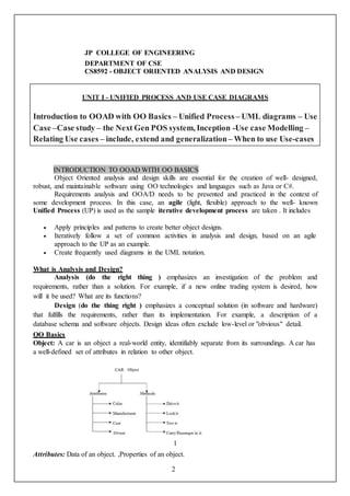
![3
Methods: Procedures of an object. or Behavior of an object.
The term object was for formal utilized in the similar language. The term object means a
combination or data and logic that represent some real-world entity.
When developing an object oriented applications, two basic questions arise,
1. What objects does the application need?
2. What functionality should those objects have?
Programming in an object-oriented system consists of adding new kind of objects to the
system and defining how they behave. The new object classes can be built from the objects
supplied by the object-oriented system.
Object state and properties (Attributes)
Properties represent the state of an object. In an object oriented methods we want to
refer to the description of these properties rather than how they are represented in a particular
programming language.
Attributes of car object
We could represent each property in several ways in a programming
languages.
For example: Color
1. Can be declared as character to store sequence or character [ex: red, blue, ..]
2. Can declared as number to store the stock number of paint [ex: red paint, blue paint,
..]
3. Can be declared as image (or) video file to refer a full color video image.
The importance of this distinction is that an object abstract state can be
independent of its physical representation.
Object Behavior and Methods:
We can describe the set of things that an object can do on its own (or) we can do
with it. For example: Consider an object car, We can drive the car. We can
stop the car.
Each of the above statements is a description of the objects behavior. The
Car
Cost
Color
Make
Model](data:image/gif;base64,R0lGODlhAQABAIAAAAAAAP///yH5BAEAAAAALAAAAAABAAEAAAIBRAA7)