SlideShare une entreprise Scribd logo
1  sur  86
Télécharger pour lire hors ligne
Ó 2012 Wiley-VCH Verlag GmbH & Co. KGaA, Weinheim
Article No : b04_477
Chemical Plant Design and Construction
ERICH MOSBERGER, Lurgi AG, Frankfurt, Federal Republic of Germany
1. Introduction. . . . . . . . . . . . . . . . . . . . . . 250
2. Feasibility Study . . . . . . . . . . . . . . . . . . 250
2.1. Initial Work. . . . . . . . . . . . . . . . . . . . . . 251
2.2. Cost Estimation . . . . . . . . . . . . . . . . . . . 252
2.2.1. Investment Costs . . . . . . . . . . . . . . . . . . . 252
2.2.1.2. Global Methods of Investment Cost
Estimation. . . . . . . . . . . . . . . . . . . . . . . . 253
2.2.1.3. Detailed Methods of Investment Cost
Estimation. . . . . . . . . . . . . . . . . . . . . . . . 254
2.2.1.4. Item-by-Item Calculation . . . . . . . . . . . . . 255
2.2.1.5. Cost Indexes . . . . . . . . . . . . . . . . . . . . . . 256
2.2.2. Operating Costs. . . . . . . . . . . . . . . . . . . . 256
2.2.3. EDP Support. . . . . . . . . . . . . . . . . . . . . . 257
2.3. Profitability Analysis . . . . . . . . . . . . . . . 257
2.3.1. Profitability Analysis as an Engineering Task 257
2.3.2. Methods of Profitability Analysis . . . . . . . 258
2.4. Site Selection . . . . . . . . . . . . . . . . . . . . . 259
2.5. Decision between Alternative Investments 259
3. Preliminary Design . . . . . . . . . . . . . . . . 260
3.1. Preliminary Design Costs. . . . . . . . . . . . 260
3.2. Final Selection of Site Locations . . . . . . 261
3.3. Process Design . . . . . . . . . . . . . . . . . . . 263
3.3.2. Optimization . . . . . . . . . . . . . . . . . . . . . . 267
3.3.3. Safety Aspects and Environmental Control 269
3.3.3.1. Protection Against Emissions . . . . . . . . . . 270
3.3.3.2. Noise Control . . . . . . . . . . . . . . . . . . . . . 270
3.3.3.3. Occupational Safety and Health . . . . . . . . 272
3.3.3.4. Plant Availability . . . . . . . . . . . . . . . . . . 272
3.3.3.5. Authority Engineering . . . . . . . . . . . . . . . 273
3.4. Basic Engineering . . . . . . . . . . . . . . . . . 275
3.4.1. Equipment Specification from the Process
Engineering Standpoint . . . . . . . . . . . . . . 275
3.4.2. Materials of Construction. . . . . . . . . . . . . 275
3.4.3. Plant Layout . . . . . . . . . . . . . . . . . . . . . . 279
3.4.4. Preliminary Piping and Instrumentation
Diagram . . . . . . . . . . . . . . . . . . . . . . . . . 281
3.5. Calculation of Plant Costs . . . . . . . . . . . 281
3.5.2. Equipment. . . . . . . . . . . . . . . . . . . . . . . . 282
3.5.3. Bulk Materials. . . . . . . . . . . . . . . . . . . . . 283
3.5.4. Other Costs . . . . . . . . . . . . . . . . . . . . . . . 284
3.6. Conclusion of Preliminary Design Phase 285
4. Contract Writing and Forms of Contracts 286
4.1. Licensing Agreements . . . . . . . . . . . . . . 286
4.1.1. Patent Licenses . . . . . . . . . . . . . . . . . . . . 286
4.1.2. Process Licenses . . . . . . . . . . . . . . . . . . . 286
4.1.3. Process Licenses viaEngineering Contractors 287
4.1.4. Know-How Contracts via Engineering
Contractors . . . . . . . . . . . . . . . . . . . . . . . 287
4.2. Design and Supply Contracts with
Engineering Contractors . . . . . . . . . . . . 288
4.2.1. Selection of Engineering Contractors . . . . 288
4.2.1.1. Importance of Risk in the Plant Business . . 288
4.2.1.2. Selection and Award Criteria . . . . . . . . . . 288
4.2.2. Form and Content of Contracts . . . . . . . . 289
4.2.2.1. Basic Concerns in Contract Writing . . . . . 289
4.2.2.2. Contract Types and Provisions . . . . . . . . . 290
4.2.2.3. Essential Elements of a Contract . . . . . . . 291
5. Execution of the Project . . . . . . . . . . . . 293
5.1. Scope of Work . . . . . . . . . . . . . . . . . . . . 293
5.2. Project Organization and Management . . 294
5.2.1. Matrix Project Management . . . . . . . . . . 294
5.2.2. The Project Manager . . . . . . . . . . . . . . . . 295
5.2.3. The Project Team . . . . . . . . . . . . . . . . . . 296
5.2.4. The Start Phase of a Project. . . . . . . . . . . 296
5.3. Project Control (Schedules, Progress,
Costs). . . . . . . . . . . . . . . . . . . . . . . . . . . 297
5.3.1. Time Scheduling . . . . . . . . . . . . . . . . . . . 297
5.3.2. Progress Planning and Control . . . . . . . . . 299
5.3.3. Cost Planning and Control . . . . . . . . . . . . 300
5.3.4. Project Report . . . . . . . . . . . . . . . . . . . . . 302
5.4. Detail Engineering . . . . . . . . . . . . . . . . . 303
5.4.1. Process Engineering. . . . . . . . . . . . . . . . . 303
5.4.2. Plant Layout . . . . . . . . . . . . . . . . . . . . . . 303
5.4.3. Apparatus and Machinery . . . . . . . . . . . . 305
5.4.4. Piping. . . . . . . . . . . . . . . . . . . . . . . . . . . 308
5.4.5. Control Systems . . . . . . . . . . . . . . . . . . . 312
5.4.6. Electrical Design . . . . . . . . . . . . . . . . . . . 315
5.5. Procurement . . . . . . . . . . . . . . . . . . . . . 316
5.5.1. Purchase of Equipment and Services . . . . 316
5.5.2. Expediting. . . . . . . . . . . . . . . . . . . . . . . . 317
5.5.3. Shipping . . . . . . . . . . . . . . . . . . . . . . . . . 317
5.6. Planning and Execution of Civil Work and
Erection . . . . . . . . . . . . . . . . . . . . . . . . . . 317
5.6.1. Planning of Civil Work and Erection . . . . 318
5.6.1.1. Planning of Civil Work (Including Structural
Steel Work). . . . . . . . . . . . . . . . . . . . . . . . 318
5.6.1.2. Erection Planning . . . . . . . . . . . . . . . . . . 319
5.6.2. Execution of Construction . . . . . . . . . . . . 319
5.6.2.1. Construction-Site Organization and
Management . . . . . . . . . . . . . . . . . . . . . . 319
5.6.2.2. Time Scheduling and Progress Control . . . 320
5.6.2.3. Construction Work . . . . . . . . . . . . . . . . . 321
DOI: 10.1002/14356007.b04_477
5.7. Commissioning. . . . . . . . . . . . . . . . . . . . 322
5.7.1. Plant Design and Commissioning . . . . . . . 322
5.7.2. Operating Manual . . . . . . . . . . . . . . . . . . 323
5.7.3. Responsibility and Organization. . . . . . . . 325
5.7.4. Preparation for Commissioning . . . . . . . . 325
5.7.5. Plant Startup . . . . . . . . . . . . . . . . . . . . . . 325
6. Computer Support. . . . . . . . . . . . . . . . . 326
6.1. Role of Computers in Project Execution 326
6.2. EDP Infrastructure and Systems . . . . . . 327
6.3. Coordination and Interfaces . . . . . . . . . 328
7. Quality Assurance . . . . . . . . . . . . . . . . . 328
8. Training of Plant Personnel. . . . . . . . . . 329
References . . . . . . . . . . . . . . . . . . . . . . . 330
1. Introduction
Since the 1930s, the design and construction of
chemical plants have become increasingly spe-
cialized. Chemists and engineers collaborate to
develop process and engineering concepts,
which engineers and designers then transform
into detailed plans and specifications for all the
components of a chemical plant. Purchasing
agents procure equipment from specialist man-
ufacturers. Construction and installation firms
are put under contract to build the plant.
Plant design and construction starts as an idea
of the potential owner. Increasingly complex
markets and the interrelations of the world eco-
nomic and political systems require critical ex-
amination of every project for feasibility, eco-
nomic relevance, and environmental impact.As a
rule, this is done with the aid of a feasibility study
that includes preliminary design work. Market
analyses are carried out to determine potential
sales, future demand dynamics, availability of
raw materials, and the competitive situation. The
plant capacity and location are specified. Partic-
ular attention must be paid to environmental
protection. Studies are supplemented by suffi-
ciently accurate estimates of capital require-
ments and profitability.
Once the decision has been made to go ahead
with the construction project, whereby the owner
may have opted not to carry it out himself, the
owner will prepare an accurate, comprehensive
definition of the plant which is used as the basis
for inviting bids from competent engineering
contractors. This approach is increasingly em-
ployed, especially for large projects. (If the own-
er has an adequate pool of experienced design
engineers, construction specialists, and procure-
ment staff, he may plan and construct the plant
himself.) The conceptual phase of the project
ends when an appropriate engineering firm is
chosen and the contract signed.
The implementation phase consists of the
engineering of the chemical plant, procurement
of plant equipment and material, construction,
and commissioning. The engineering contractor
either performs all of these tasks or brings in
subcontractors or personnel employed by the
owner to carry out a portion of the work.
Plant equipment is fabricated by specialized
manufacturers. Only in rare cases does the engi-
neering contractor or the plant owner have pro-
duction facilities.
After a successful test run, the plant is handed
over to the owner. (Fig. 1 shows a schematic
diagram of the development of a chemical plant
project.)
This article does not discuss the design and
construction of small, simple plants that special-
ized firms can supply ‘‘off the rack.’’ It deals with
larger, more complicated projects in the field of
chemical plant construction. The term chemical
plant design and construction is used in a very
broad sense. It also relates to allied technologies,
such as metallurgy, environmental protection,
fiber and food production, and petroleum and
natural gas processing. Some of these basic
project development and execution principles
can also be applied to general industrial plant
construction.
2. Feasibility Study
At the start of a project, the bases used for
planning are still very inexact. No major costs
should be incurred until it is known whether the
project is feasible or not. Nevertheless, all alter-
natives must be considered. A great deal of
experience is needed if uneconomic variants are
to be discarded without generating high design
costs. The first steps toward accurate definition of
the project are carried out by the company that
wishes to erect the plant. A small working group
250 Chemical Plant Design and Construction Vol. 8
is formed, consisting of process engineers, sales
engineers, and other engineering personnel. It is
useful to appoint a project leader to coordinate
the team. Normally, the same person will later
become responsible for implementing the project
if the decision is taken to proceed.
Preliminary studies aimed at defining the
objective partly depend on initial economic es-
timates and generally include:
1. Market analysis and trend analysis
2. Fixing of production capacity
3. Examination of competing processes and of
the patent and license situation
4. Legal aspects
5. Estimation of investment costs
6. Estimation of production costs
7. Estimation of profitability
8. Selection of an appropriate plant location
2.1. Initial Work
Market Analysis and Production Capa-
city. Before the economically optimum plant
capacity is set, a careful market analysis must be
carried out. This analysis must be performed by
experienced market analysts, even if the product
has a comprehensive international sales history.
These specialists evaluate literature on the de-
velopment of similar products, determine the
capacity of existing production facilities, carry
out representative surveys, obtain suitable con-
ditions from downstream processors in the case
of intermediate products, and forecast the future
market for the product. They must also provide a
realistic evaluation of the competition and the
world economic situation. Forecasts of costs for
raw materials and working capital play an im-
portant role in the economic analysis.
A new chemical product usually experiences
slow early growth with a relatively high price and
low output. The market then expands; production
climbs faster and prices drop. Finally, prices
stabilize at a low level, and older, smaller plants
are shut down (see Fig. 2). If market analysis
shows that world output of the product is still
increasing rapidly, expansion of capacity
through erection of a new plant may have a good
outlook if other conditions are favorable. The
future price decline must, however, be allowed
for in the calculations.
In the upper part of the trend curve, invest-
ment only makes sense if a clear demand is
Figure 1. Development of a project
Vol. 8 Chemical Plant Design and Construction 251
perceptible in the market. The production curve
for the old process may fall off if a new, more
economical production process appears. (Exam-
ple: low-pressure process for methanol produc-
tion forces shutdown of older high-pressure pro-
cess.) The new process may open up new markets
and lend new impetus to development [1–4].
Competing Processes, Patent and License
Situation. The patent and license situation
must be investigated at the beginning of the
study. Foreign patents may block the construc-
tion project if the owner of the patent is not
prepared to grant a license (see also Chap. 4).
Legal Aspects. Extensive, far-reaching en-
vironmental regulations mean that it is essential
to make an early approach to authorities that will
later have to approve the operation of the plant
(see Section 3.3.3.5).
2.2. Cost Estimation
If initial planning work has shown that invest-
ment is desirable and the market analysis has led
to a tentative capacity figure, a first estimate of
investment costs and subsequent operating costs
is performed.
Simply calculating and analyzing the invest-
ment costs is not sufficient because, over the
service life of a plant, operating costs make up
a much greater proportion of life- cycle costs than
investment costs do. The goal of cost estimation
in the conceptual phase is to optimize the life-
cycle costs of a chemical plant. This often means
increasing investment costs so as to lower oper-
ating costs. Operating costs are favorably influ-
enced by long component and equipment life-
times, improvements in maintenance and con-
sumption, and other factors. Cost prediction as
the basis for profitability analysis should there-
fore include the determination of investment
costs as well as subsequent production and oper-
ating costs.
The following sections discuss methods of
determining investment and operating costs.
2.2.1. Investment Costs
A proven technique in investment cost estima-
tion is to subdivide the project into onsite and
offsite items.
Onsite Items. The term onsites denotes all
facilities required to make the desired product.
Offsite Items. Offsites are all facilities that
are normally not located within the process plant.
They include facilities for the delivery of steam,
electric power, gas, solid or fluid fuels, water,
compressed air, and instrument air. Furthermore,
this group includes stockpiles and warehouses
for raw materials and semifinished and finished
products; service facilities (administrative build-
ings, canteens, workshops, stores, laboratories,
parking, fire protection, roads, tracks, and harbor
facilities); and, finally, power plants; loading
docks; facilities for treating raw materials, off-
gas, wastewater; and waste disposal facilities.
In the United States, offsites are usually di-
vided into storage and handling (stocks of raw
materials and finished products), utilities (gener-
ation or delivery of energy as steam, electricity,
and water), and service facilities (e.g., offices,
recreation rooms, laboratories, workshops,
warehouses).
On grounds of cost, an attempt must be made
to carry out an ‘‘order-of-magnitude’’ estimate at
minimal cost. This estimate is of course inexact,
but later it makes it easier to decide whether to
bear the costs for an accurate analysis. The
approximate determination of investment costs
is subdivided into simple ‘‘global’’ methods and
‘‘detailed’’ methods. Methods for estimating in-
vestment costs are now well-established; those
now in use are described in publications mainly
dating from 1960 – 1984.
Figure 2. Development of a new product
252 Chemical Plant Design and Construction Vol. 8
2.2.1.2. Global Methods of Investment Cost
Estimation
Global methods permit investment costs to be
estimated relatively easily and with an accuracy
between Æ 30 % and Æ 50 %. Several methods
are outlined below [5].
Single Complexity Factor. In the single-
complexity-factor method [6] processes are clas-
sified as having a low, medium, or high com-
plexity factor.
Low Complexity Factor. This class includes
all batch processing plants and all processes
involving simple syntheses (e.g., production of
sulfuric acid).
Medium Complexity Factor. This class
comprises processes with gas and fluid phases
that run at ordinary pressures and temperatures.
High Complexity Factor. This class covers
processes with high pressures and/or tempera-
tures, as well as polymerization processes.
Investment costs depend on the complexity
factor and the required plant capacity, and are
determined from empirical data obtained in other
processing plants. Auxiliary and utility units are
taken into account by adding 45 %.
This method has the advantage that it permits
estimation of investment costs in the orientation
phase when little information about the process is
available.
Turnover Ratios. The turnover-ratio meth-
od allows costs to be estimated without process
information by using market information such as
product sale price and sales volume [7].
On the basis of plants already on-stream, a
capital turnover ratio is obtained by dividing the
annual return on sales by the investment costs. A
statistically determined turnover ratio and an
expected annual return on sales are then used to
estimate the investment costs of new plants.
Turnover ratios in the chemical industry lie
between 1.2 and 1.5.
Statistical turnover ratios can be found for the
analysis of individual plants, companies (based
on balance sheets and profit-and-loss statements
of typical firms), or a whole industrial sector.
Degression Exponents. The use of degres-
sion exponents (cost-versus- capacity exponents)
per-mits relatively accurate cost estimation. The
technique is based on costs for plants already on-
stream. The exponents are used to estimate in-
vestment costs for the planned facility as a func-
tion of plant capacity.
Investment costs for proces plants are pub-
lished from time to time and can be used for
initial cost estimation. The costs of identical or
similar plants within the same company can be
used in a similar way.In 1967, J. E. HASSELBARTH
[8] published the costs of process plants for 60
chemical products, including investment costs
per tonne of annual capacity. His figures referred
to costs within battery limits (i.e., within the plant
boundary), exclusive of land and offsite facili-
ties. In 1970, K. M. GUTHRIE [9] compiled the
investment and operating costs for 54 chemical
and refinery processes covering a wider capacity
range. The degression exponents cited in both
publications allow the calculation to be applied to
other capacities. (Example: Given a degression
coefficient of 0.7, doubling the capacity leads to
an increase in investment costs by a factor of
20.7
¼ 1.65.)
When specific degression exponents are used
it should be noted that the error range grows with
the capacity scaling factor. This type of calcula-
tion generally gives acceptable results only for
scaling factors of up to 1: 3. Furthermore, the use
of the method depends on the state of the art
because changes in processes, apparatus, and
mechanical technique can change the exponents.
Comparative Methods. When adequate
data are available from an existing plant similar
to that being planned, the investment costs of the
old plant can obviously be used to calculate the
costs of the new one.
The following information is needed [5]:
1. Production capacity
2. Construction time
3. Investment costs (inside and outside battery
limits)
4. Location
Costs inside and outside battery limitsare both
determined with degression exponents. Cost es-
timation outside battery limits must, however, be
preceded by a critical analysis of the auxiliary
and utility units needed. The figures are adapted
to the location by the use of indexes to adjust for
the following [5]:
Vol. 8 Chemical Plant Design and Construction 253
1. Construction location
2. Economic situation of the industry
3. Taxes
4. Labor market
5. Qualifications of available labor
2.2.1.3. Detailed Methods of Investment Cost
Estimation
If the preliminary planning as embodied in
technical documents has reached an advanced
stage, it can form the basis for investment
cost estimation that takes into account specific
details of the project. Methods used for this
are mainly based on analogies with plants that
are already on-stream. Detailed methods of
plant matching [10] and multiplication-factor
techniques of cost determination are emp-
loyed.
Lang Factor Method. If the process is well
characterized, the required capacities of fur-
naces, apparatus, and machinery can be specified
in preliminary flow sheets [11]. These specifica-
tions cover main plant items such as furnaces,
columns, filters, reactors, heat exchangers, ves-
sels, and machinery. The estimator can determine
the costs ‘‘free-on-site’’ for such items or obtain
the costs from suppliers.
LANG used cost analyses of existing plants to
derive multiplication factors that allow determi-
nation of the investment costs for process units
within battery limits if the costs of the main
equipment items are known [12]. The factors
depend on the type of plant. LANG distinguishes
three types according to the state of aggregation
of the raw material and product: ‘‘solid’’ (e.g., ore
sintering), ‘‘solid – fluid’’ (e.g., oil – shale re-
torting with shale – tar recovery), and ‘‘fluid’’
(e.g., petroleum refineries, petrochemical plants).
If the costs for the main plant items are taken
as 100, total processing-plant costs are found by
multiplying by 3.10 (solid-processing plant),
3.63 (solid – fluid-processing plant), or 4.74
(fluid-processing plant).
CHILTON [13] and HAND [14] have improved
these approximate Lang factors by introducing
supplements to the costs of main equipment
items. Estimates of the total costs of a ‘‘grass-
roots’’ plant can then be made. Figure 3 outlines
the procedure for preliminary calculations by the
Lang – Chilton method.
Other authors have extended and refined the
Lang method. For example, BURGERT in 1979
published an analysis of investment- cost struc-
tures for more than 100 projects [15].
In 1965, MILLER [16] devised another system
based on modified Lang factors. MILLER assumed
that the factors are influenced by three other
parameters besides those used by LANG (solid,
solid – fluid, fluid):
1. Size of main equipment items
2. Material from which the plant is constructed
3. Pressure for which the plant is built
Increasing size, more refined materials, and
higher operating pressure increase the relative
costs of the main equipment items in relation to
storage, utilities, and service facilities, thus di-
minishing the factors. According to MILLER, all
factors can be referred to the mean per-piece
costs of plant parts and depend on these.
Guthrie’s Modular Technique. The mod-
ular technique published by GUTHRIE [17] in 1968
is also based on LANG’s method and is the best of
the multiplication-factor approaches. The project
is first broken down into six modules [10]:
Five direct modules
Chemical processes
Solids handling
Site development
Industrial structures (civil work)
Auxiliary and service facilities outside battery
limits (offsites)
One indirect module
Indirect project costs
The key costs of the direct modules are deter-
mined first. For the ‘‘chemical process’’ module,
these might be costs for machinery and equip-
ment. As shown in Figure 4, the key costs of the
direct modules are multiplied by the gross mod-
ule factors. The sum of the individual ‘‘gross
module costs’’ gives the investment costs for on-
and off-battery facilities.
GUTHRIE proposes a variety of methods for
calculating the equipment costs of a module. The
multiplication factors required for this include
not only size of the component (magnitude fac-
tor) and the alloy factor, but also indirect effects.
254 Chemical Plant Design and Construction Vol. 8
This relatively accurate modular technique has
not found wide acceptance, however, because it
is relatively difficult to perform the calculation
and maintain the statistical data base.
2.2.1.4. Item-by-Item Calculation
When detailed methods of investment- cost esti-
mation do not give sufficient accuracy, the only
alternative is to calculate investment costs item
by item. The plant equipment and the engineer-
ing work must be specified. The procedure and
amount of work required for such a cost estima-
tion are the same as those described for calculat-
ing plant costs (see Section 3.5). Close coopera-
tion between the subsequent operator of the plant
and an engineering firm has proved advantageous
for this approach.
Figure 3. Preliminary cost estimate using factors (Lang – Chilton method)
Vol. 8 Chemical Plant Design and Construction 255
2.2.1.5. Cost Indexes
The methods of investment-cost estimation dis-
cussed above are generally based on historical
statistics derived from existing plants. The cost
figures obtained by these methods are therefore
referred to given periods, such as 1985. If invest-
ment costs are to be estimated for the year 1990,
the estimates must be adjusted to current prices.
Every industrial country publishes one or more
indexes for this purpose. Some widely used
indexes for the United States and Germany
follow:
1. Bureau of Labor Statistics cost index for
equipment, machinery, and materials in the
U.S. market
2. Chemical Engineering Plant cost index
[18–20]
3. K€olbel – Schulze index for chemical plants
(K€olbel – Schulze Index f€ur Chemieanlagen)
[21]
4. Producer price index for commercial products
(Index der Erzeugerpreise gewerblicher Pro-
dukte) compiled by the German Federal Sta-
tistical Service (Statistische Bundesamt)
These indexes are based both on chemical-
plant cost structures and on national primary
price indexes. Figure 5 compares important cost
indexes over time.
2.2.2. Operating Costs
Along with the investment costs, the operat-
ing costs incurred in the production of a given
product also play an important part in deciding
Figure 4. Simplified modular concept for estimating investment costs
F ¼ net module factor; F2 ¼ gross module factor
Figure 5. Development of cost indexes
a) CE Plant cost index, 1959 ¼ 100, successively published
in [18] (1982 revision of productivity factor from 2.50 to
1.75); b) K€olbel – Schulze index, 1976 ¼ 100, successively
published in [19]
256 Chemical Plant Design and Construction Vol. 8
whether to erect a plant. The technical and eco-
nomic literature, however, contains little infor-
mation on the preliminary calculation of operat-
ing costs. Possible reasons are the complexity of
the problem and the company’s possible loss of
maneuvering room if internal operating data
were published [22].
The methods of estimating operating costs
discussed below are based on data from compa-
rable plants or empirical data from plants belong-
ing to the same company [22].
They are related, but differ as regards starting
information: published data, empirical data,
business information, physical data, correlations,
and information from comparable plants. In or-
der to check the reliability of the results, operat-
ing costs should be estimated by several methods
so that the calculations can be verified and error
ranges given.
Graphical Method. The graphical method
is based on statistical evaluation of operating
costs in existing plants. Operating costs per unit
of product are plotted versus plant capacity. It is
important to be aware of the scope of the plotted
costs. The graph usually includes only the
manufacturing costs of a product: raw materials,
power, catalysts, chemicals, wages, depreciation,
and maintenance. Plant overheads, fixed costs,
and indirect production costs should also be
taken care of by multiplication factors.
Business Analysis. The analysis of bal-
ance sheets and profit-and-loss statements
from companies that manufacture the product
in question as their main commodity may also
be helpful.
Energy-Based Methods. Chemical produc-
tion processes involve large amounts of energy.
The chemical reactions themselves often contrib-
ute very little to energy requirements but up-
stream and downstream operations do. This fact
provides the basis for several methods used to
estimate operating costs [13], [23–25].
Key Cost Categories. If it is assumed that
chemical plants show relatively constant operat-
ing- cost structures for a given product, operating
costs can be calculated with multiplication fac-
tors if a single cost category is known accurately
[22].
Scaleup Methods. When operating costs for
similar plants are known,specific data can be
used to derive scaling coefficients for propor-
tional, personnel-dependent, and investment-
dependent costs. The operating costs can then
be estimated.
2.2.3. EDP Support
A number of manufacturers and operators have
established electronic data processing (EDP)
programs for estimating investment and operat-
ing costs. Examples are Factest (ICI) [26] and the
ASPEN package [27]. The ASPEN PLUS soft-
ware, a flow sheet simulation program, is sup-
plemented with a costing module.
The program sizes the most important
equipment and machinery from the process
simulation. Investment costs are estimated by
the use of multiplication factors and cost
indexes to adjust to current price levels.
ASPEN PLUS allows the calculation not only
of fixed costs for an investment, but also
operating costs.
To determine operating costs, the program
calculates fixed and variable components sepa-
rately. Variable costs include raw materials,
fuels, catalysts, disposal, and ‘‘running royal-
ties’’. Fixed costs comprise personnel costs for
maintenance and operation, overheads, insur-
ance, and taxes. The program generates summa-
ries and details of annual operating costs. Finally,
the software can evaluate avariety of profitability
measures (Section 2.3).
2.3. Profitability Analysis
2.3.1. Profitability Analysis as an
Engineering Task
In profitability calculations, it is necessary to
keep in mind that a plant erected without reserves
(standby units) for unavoidable shutdowns and
repairs will produce for only 330 days (or
8000 h) a year; that is, it will attain only ca.
90 % of rated capacity on a long-term basis.
Manufacturers generally rate their equipment for
operation at 10 % over capacity. However, this
figure only applies to intermittent overloads and
is not guaranteed.
Vol. 8 Chemical Plant Design and Construction 257
If full-load operation is required all year, the
plant must not be designed as a single-train
(single processing line) facility, unless it is set
up for 110 % capacity and adequate storage is
provided for the finished product. Large storage
areas are needed if sales are seasonal (e.g.,
fertilizers).
Because the feasibility study includes com-
parisons between alternative processes, two pro-
cesses with equal profitability need not be ranked
equally. For example, both may have equal
production costs but different fixed costs.
Fixed costs usually comprise interest pay-
ments and operator wages. Nearly all other costs
depend on output and are therefore variable (e.g.,
costs of raw materials, power, and fuel). If
market conditions make it necessary to reduce
the output to, say, 80 % of rated capacity, the
plant with high fixed costs will become unprofit-
able more quickly. Thus, in the case of two
equally profitable plants, the plant with the lower
fixed-cost contribution will be preferred. High
fixed costs often have to be accepted, if the need
for reliable operation dictates that critical parts of
the plant must be designed with 100 % standby
capacity or the plant must be subdivided into
parallel trains.
The profitability calculations must take into
account that 2 – 2.5 years usually elapse be-
tween the start of planning and the commission-
ing of the plant. Interest therefore has to be paid
on design and construction costs. Working capi-
tal is also needed for storage of raw materials and
product. Finally, for technical or market-related
reasons, a period of 6 – 12 months generally
elapses after commissioning before the utiliza-
tion of the plant is sufficient to cover the costs
(break-even point). Only then does the return
flow of capital begin.
The history of an investment is illustrated
schematically in Figure 6.
2.3.2. Methods of Profitability Analysis
Methods for assessing the profitability of a proj-
ect [1, pp. 285 – 401], [28–33] differ in the way
investment, revenue, and risk are associated. The
three most important techniques are described
briefly below.
These profitability calculations are combined
and linked with operations research techniques
[34], [35], so that alternative proposals can be
obtained with a justifiable amount of effort.
Payout (Payback) Period. If alternatives
are only to be compared, it may be adequate to
divide invested capital by gross excess revenues
(proceeds from sales minus operating costs).
This method gives a quick indication as to
whether the investment is attractive. If, for
example, a value of 3 (payout period 3 years)
or less is obtained, the investment should be
profitable. This does not mean, however, that the
plant will be completely written off after three
years on stream.
A more realistic figure can be obtained by
including taxes and interest under expenses and
listing revenues by year after commissioning
(higher operating costs in the first year when full
capacity has not been reached, future decline in
earnings).
Return on Investment (ROI). In large
chemical companies, investments depend not so
much on the payout period but on whether the
investment will increase total profits, i.e., divi-
dends to the stockholders. Thus a large company
will only invest if a certain return on invested
capital is ensured. The ROI method is employed
in such cases. The annual profit before taxes and
interest, but after depreciation, is divided by the
invested capital. In contrast to the preceding
method, startup losses are neglected and data
for design- capacity operation are used in the
Figure 6. Schematic showing the course of capital
investment
a) Accumulated profits; b) Return on investment; c) Total
production costs (fixed and variable); d) Fixed costs; e) Ac-
cumulated cash flow
258 Chemical Plant Design and Construction Vol. 8
calculation. The result is a pretax rate of return on
invested capital.
Dynamic Calculations are based on the
discounted cash flow (DCF) method. The DCF
method is an advance over ROI. It allows for the
fact that investment costs precede revenues.
Since only funds existing at the same time can
be compared, all revenues and expenses that are
directly or indirectly related to the project from
the start of planning onwards are discounted to a
fixed time, usually the start of production. A rate
of return is then sought that makes the sum of the
discounted annual excess revenues equal to the
cash value of the total investment at the start of
production. Since excess revenues are spread
throughout the entire year, they are all recalcu-
lated to the middle of the year and discounted
from then on. The calculation runs over the
economic life of the project, but usually only
10 years, since the longer-term market position
can scarcely be foreseen. Furthermore, the equiv-
alent value of revenues after more than 10 years is
so small that it has little effect on the result
(internal rate of return).
2.4. Site Selection
The selection of an optimal site is a high-priority
item in the feasibility study. Every economic
region has its advantages and disadvantages. The
present and future importance of correct site
selection can scarcely be overstated. Wrong site
choices cannot be corrected later and have led to
the downfall of many companies.
The development of world trade and the de-
cline of tariffs have changed the environment of
many existing plants for the worse. Formerly, for
example, the steel mill was located near the coke
plant and iron ore transported to it. Today, the
most important Japanese steel mills are located
on the coast and import coal and ore from over-
seas. Petroleum refineries used to be sited at
petroleum sources. Now that giant tankers and
pipelines have come into wide use, refineries are
often located in consumption centers.
Many large chemical companies are now in-
vesting in coastal and foreign property. Good
surveys of publications important in site selection
can be found in [1, p. 439], [36–38]. STOBOUGH
has devised a selection system, based on a point
ranking, which allows unsuitable sites to be elim-
inated quickly. The short list of remaining sites
should then be examined as described below.
Site Quality, Topography, Soil Conditions,
Climate, Flood Risk. The short list should in-
clude only locations that appear suitable for the
plant and possible subsequent expansions from
the standpoint of size, price, transportation facil-
ities, and buildability.
If the terrain is not flat, it should be established
whether grading or filling is necessary and
whether piles must be driven for foundations. If
transportation facilities (roads, railroad tracks,
water routes) are lacking, the expense of devel-
oping them must be ascertained. Only costs for
developed sites can be compared.
Raw-Material Availability Including
Power, Fuels,andWater. Rawmaterialsofgood
quality must be available at a favorable price
throughout the service life of the plant. Other
prerequisites are availability of sufficient fresh
water, electric power, and fuels. Obtaining power
and steam on a grass-roots site can be expensive.
Environmental Conditions, Environmental
Legislation, and Infrastructure of the Con-
struction Site. Improved roads, rail connections,
and location on harbors or year-round navigable
rivers are important criteria.
Long-Term Availability of Qualified
Labor. In developing countries, leading person-
nel – from foremen to management – must meet
very stringent requirements. Only after years of
schooling will local personnel have the required
standard of education.
Raw-material costs, wages, and maintenance
costs are also crucial in site selection. Finally, it
must be taken into account that the phase of
startup losses will be longer if an industrial site
has to be developed from scratch.
2.5. Decision between Alternative
Investments
Preparation for Decisionmaking. Large
investment projects involve exploration of wide-
ly varying options. In addition to straight profit-
ability analysis, qualitative factors should also be
considered (e.g., special site problems, political
environment, market development). These
qualitative factors involve risks, which must
also be assessed. The preparation phase for
Vol. 8 Chemical Plant Design and Construction 259
decisionmaking therefore includes not only cal-
culation of investment and operating costs, but
also risk and sensitivity analysis [39].
Risk Analysis. In risk analysis, all constraints
that can have an adverse effect on life- cycle costs
and earnings must be identified, documented, and
assessed. These include:
1. Estimation of sales market
2. Energy cost development
3. Availability of raw materials
4. Plant construction risks
5. Management-related risks (e.g., site-depen-
dent problems, reliability of vendors and
subcontractors)
6. Organizational risks
The financial effects of the identified risks are
quantified by experts in risk-assessment proce-
dures and the results then evaluated in a Monte
Carlo simulation [39].
Sensitivity Analysis. Sensitivity analysis
should be carried out to find out how the profit-
ability and risk situation changes when certain
assumptions and constraints are varied. For ex-
ample, it might be asked how much the invest-
ment costs would have to be reduced to allow the
desired profit and an acceptable amortization.
A calculation of annual revenues based on the
quantity of product that can be sold in the market
and its price allows a variational calculation of this
type to be made. The expected profit is deducted
from the sum over the project life. The remainder
represents the maximum available investment and
operating costs that have to be optimized in several
steps. This approach is called ‘‘design to cost.’’
Investment costs are often minimized in this ap-
proach by designing low- cost plants (usually
open-air plants with simple equipment and no
storage capacity for intermediate products).
Several iterations are usually required to reach
an optimum between investment costs and oper-
ating costs.
Decisionmaking. Profitability, sensitivity,
and risk analyses may lead to the conclusion that
execution of the project is not desirable. Recent
publications may have already shown that similar
projects undertaken by third parties will oversat-
urate the market. Other companies may have
access to such good raw-material sources that
the company considering the project cannot com-
pete. It may be that environmental regulations
have a prohibitive effect on costs. The planning
work should then be stopped until new informa-
tion or analyses suggest a different conclusion.
The avoidance of huge losses on a badly planned
facility far outweighs the costs incurred up to this
point. If, however, the feasibility study reveals a
positive situation, the next step is to incorporate
the capital requirement into the company’s in-
vestment program and give the go-ahead to start
preliminary design.
3. Preliminary Design
The following results from the feasibility study
provide the basis for deciding to proceed to the
preliminary design phase:
1. Plant capacity has been set on the basis of
market research
2. The choice between expansion of an existing
facility and construction of a new one has
been made
3. The list of potential sites has been shortened to
two or three alternatives
4. The projected capital outlay has been
determined
5. The projected production costs for the product
have been determined
6. The payout time and profitability have been
estimated
The main task in preliminary design is to
obtain a more exact calculation that takes into
consideration all costs up until commissioning.
The first step toward this objective is to work out
the engineering details.
A qualified project leader directs the prelimi-
nary design. Specialist engineering teams (e.g.,
for process calculations, equipment design, plant
layout, and estimations) provide advisory sup-
port [40].
3.1. Preliminary Design Costs
The funds and time spent on preliminary design
can be considerable, depending on how pre-cise
planning and budget are to be. Although highly
260 Chemical Plant Design and Construction Vol. 8
accurate results are always sought, technical
documentation and calculations should be re-
fined only to the degree necessary for subse-
quently deciding whether to implement the proj-
ect. Events during the preliminary design period
may force the abandonment of the project.
If the feasibility study predicts very favor-
able profitability, less accurate calculations (say
Æ 20 %) may be acceptable; if the project is
expected to be marginally profitable, better
accuracy (e.g., Æ 10 %) is needed. Figure 7
[41] shows the basic information required for
given accuracy levels. Even if the upper and
lower limits of the percentage ranges in Figure 7
are made equal, the probability of exceeding the
projected costs is greater than that of falling
short of them. This is primarily due to subse-
quent additions that are not known at the time
when the calculation is performed. A ‘‘contin-
gencies’’ item is therefore commonly included
in the calculation.
Design costs for preliminary calculations at
various accuracy levels, according to the Ameri-
can Association of Cost Engineers [42], are pre-
sented in Table 1. Specific empirical figures are
given in [43].
Preliminary design requires a special project
team consisting of persons with the necessary
expertise. A chemical company whose engineer-
ing staff is oriented mainly toward maintenance
and the occasional addition of new pieces of
equipment should not attempt to perform the
preliminary design of a large plant or a branch
plant in-house. Such a department lacks appro-
priate experience and is also short of capacity.
The need to hold down design costs and maintain
the performance level of in-house engineering
staff on their specific tasks, forces even large
chemical firms to collaborate closely with exter-
nal engineering contractors who will later be in
charge of executing the project. External engi-
neering firms usually offer cost advantages be-
cause they have so much experience in their
routine fields that they can quickly estimate
reliable cost figures for projects based on well-
known processes.
The client’s role is limited – at least as far as
established processes are concerned – to making
process knowhow available, purchasing li-
censes, and cooperating with the engineering
contractor in customizing the plant to relevant
requirements.
Contract forms have been developed for the
collaboration between the customer and the en-
gineering firm in the basic-design and/or detai-
lengineering phases, as well as for procurement,
supply, construction, construction supervision,
and commissioning (Section 4.2.2).
Another option for cutting design costs is for
the chemical firm to obtain a process license, with
the licenser providing the complete ‘‘basic
design.’’
3.2. Final Selection of Site Locations
After the feasibility study two or three suitable
sites are often available for the new plant. A
final decision can be made only after detailed
study.
If the potential sites are close to the client’s
parent plant, similar fringe conditions can be
assumed to apply for the purpose of site compar-
ison.If, however, abranchplant is to be erected in
a foreign country, conditions are usually differ-
ent which means that each of the alternatives has
to be carefully analyzed.
Important constraints besides those already
listed in Section 2.4 include:
1. Medium- and long-term capacity of the local
(national) market to absorb the product
2. Export to nearby countries
3. Availability, quality, and price of raw
materials
4. Political situation and risks (e.g., risk of
nationalization)
5. Tax laws, tariffs, possibility of repatriating
profits
If, for example, one country has cheap raw
materials but a limited capacity to absorb the
product, partial upgrading of the raw material and
fabrication of intermediate products should be
considered. Manufacture of the end product
would then take place where there is adequate
long-term demand and a suitable distribution
network.
A team of the client’s experts should perform
a thorough on-site examination of each alterna-
tive before the final decision is made; close
contact with national and local government agen-
cies is important. The recommendations of this
team should weigh heavily in the choice of site.
Vol. 8 Chemical Plant Design and Construction 261
Figure 7. Accuracy of cost assessment based on available information [41]
262 Chemical Plant Design and Construction Vol. 8
Partnership with qualified domestic enter-
prises is becoming increasingly popular (e.g.,
joint ventures).
3.3. Process Design See also ! Process
Development, 1. Fundamentals and
Standard Course
The feasibility study defines the process objec-
tive, i.e., it specifies products (type and quantity),
feedstocks and auxiliaries (type and quantity),
and local conditions (environmental situation,
elevation, climate, energy situation). This objec-
tive, together with the overall state of the art and
the experience of the operater, licenser, or plant
design and construction contractor, provide the
basis for process selection.
Process selection can be done most simply in
the form of a block flow diagram (Fig. 8), in
which each block represents a unit operation or,
in complex plants, a plant section containing
Table 1. Design costs for cost estimates [43]
Type of estimate Synonymous terms Accuracy, % Costs as percentage
of project value
Order of magnitude estimate ratio estimate Æ 30 – Æ 50 0 – 0.1
seat of the pants estimate
ballpark estimate
guesstimate
Study estimate evaluation estimate Æ 20 – Æ 30 0.1 – 0.2
predesign estimate
factored estimate
Preliminary estimate sanction estimate Æ 10 – Æ 25 0.4 – 0.8
funding estimate
authorization estimate
budget estimate
Definitive estimate project control estimate Æ 5 – Æ 15 1 – 3
Detailed estimate tender estimate Æ 2 – Æ 5 5 – 10
contractor’s final
cost estimate
Figure 8. Block flow diagram (olefin plant)
Vol. 8 Chemical Plant Design and Construction 263
several unit operations. The blocks are joined by
lines representing the principal material and
energy streams.
The first step in process design is to establish
the operating parameters for the major stages in
the process:
1. In the case of chemical reactions, the pres-
sures, temperatures, concentrations, reactor
type, and reactor size are defined or estimated
on the basis of the reaction kinetics and
experience gathered in existing plants
2. In the case of mixing (stirring, gas disper-
sion, suspension) or separation (distillation,
drying, precipitation, filtration) of sub-
stances, the pressures, temperatures, con-
centrations, and type and size of apparatus
are defined or estimated on the basis of
established rules.
If information needed for setting the operat-
ing parameters or designing reactors/apparatus
is not known, it must be obtained in bench or
pilot-plant tests or calculated approximately on
the basis of similar reactions or unit operations.
The unit operations used in process engineer-
ing are described in [44–49].
Process Flow Diagram. The next step is to
prepare a process flow diagram from the block
flow diagram. Standard symbols (e.g., defined in
DIN 28 004) are used to represent reactors and
other apparatus, including equipment for con-
veyance and control of important streams.
In complex plants, it may be necessary first to
prepare a synoptic flow diagram (Fig. 9) and then
to draw up individual flow diagrams, giving the
needed detail for plant sections and auxiliary
operations.
Determination of Final Process Data.
When the desired effective operating time per
year has been set (e.g., 8000 h, corresponding to
91 % availability), the design capacity of the
plant (i.e., the mass throughput per unit time) is
defined. The next step is to compile the specifica-
tions for all feedstocks, auxiliaries, catalysts,
utilities, and end products, and to estimate what
intermediate products are to be expected. These
specifications include relevant physical and
chemical properties as well as the battery-limit
states of all substances received and shipped.
On the basis of the process flow diagram, the
preliminary process parameters, and the above-
mentioned specifications are used to prepare
material and energy balances for the process
steps and finally for the entire process. This
objective is not generally achieved in a single
set of computations. The experienced process
engineer must use an iterative procedure to mod-
ify the process flow diagram and/or the process
parameters so that a closed material and energy
balance is attained as simply as possible. The
following must always be ensured:
1. Compliance with emission limits.
2. Plant safety (i.e., adequate margins of safety
relative to critical operating conditions).
3. Maintenance of product quality.
4. Control of startup operations and of planned
and unplanned shutdowns. This includes
specification of components and media re-
quired (e.g., heatup burners, cooling and
purge gases, and pressure-reducing valves).
These calculations must also take account of
long-term effects, such as increasing contamina-
tion (resulting in a higher pressure drop and less
efficient heat transfer) or aging of catalysts
(lower conversion, changes in temperature and
concentration profiles).
The calculations give mass and energy values
for all important points of the plant, preferably
downstream of each unit operation. The mass and
energy flow rates and the final process parameters
are tabulated at the foot of each process flow
diagram and keyed to points in the plant
(Fig. 10).
The preliminary sizes of the reactors and
apparatus are now checked and, if necessary,
modified in the light of the final process
parameters.
If a plant is to be operated at reduced capacity
for short or long intervals, appropriate calcula-
tions must be performed. If unacceptable operat-
ing conditions or bottlenecks are found in certain
plant sections, additional measures must be taken
(e.g., supplementary heating, gas recycle, or the
partial shutdown of some unit operations). A
similar treatment applies when occasional over-
loading of the plant is expected.
Other factors are then determined, namely the
quantities of substances that have to be available
264 Chemical Plant Design and Construction Vol. 8
Figure9.Overallprocessflowdiagram(olefinplant)
Vol. 8 Chemical Plant Design and Construction 265
for the initial charges and the storage capacities
(including those outside the battery limits) need-
ed for feedstocks, auxiliaries, intermediates, and
end products.
Finally, a detailed process description is writ-
ten. Assessments of known processes are avail-
able on a subscription basis from Chem Systems
Inc. and SRI International. A survey of produc-
tion processesfor initial and intermediate organic
products is given in [50].
Process Simulation. Process design calcu-
lations for multistage, interconnected processes
with material and energy recycle soon become
Figure 10. Individual process flow diagram for a plant section
a) Heat exchanger; b) Purification tower; c) Control valve; d) Block valve; e) Steam trap; f) Blind; g) Control loop (temperature,
pressure, flow)
266 Chemical Plant Design and Construction Vol. 8
very complex. Computer tools enable designers
to develop key concepts in a reasonable time and
thus to optimize the process according to certain
criteria (investment cost, yield, energy economy,
production costs). ‘‘Flow sheeting’’ programs are
complicated computer programs that model unit
operations mathematically and allow them to be
interconnected. A plant can thus be represented
as a network of unit operations with material and
energy streams and thus simulated [51], [52]. The
material and energy balances can be calculated as
functions of the process parameters. An iterative
procedure can be carried out to bring the balances
to equilibrium for individual and interconnected
unit operations.
Simulation programs are available for steady-
state operation and dynamic conditions (e.g.,
ASPEN PLUS, DESIGN II, PROCESS, HYSIM,
and SPEED UP).
Design calculations for reactors and other
equipment (e.g., heat exchangers) can be per-
formed with special-purpose design programs and
process simulation packages. The program for a
fired tubular furnace (e.g., steam reformer) allows
calculation of process conditions as a function of
the configuration and geometry of the tubes, bur-
ners,andcombustionchamber.Animportantfunc-
tion of such programs is to simulate the equipment
when connected into systems and to identify and
remedy bottlenecks (de-bottlenecking).
Process simulators have integrated substance
data bases that meet the needs of most applica-
tions. Further data can be obtained from data
bases [53] and compilations of physical and
chemical data [54–56]. Proprietary data and em-
pirical factors (interactions, long-term effects)
can also be input.
3.3.2. Optimization
The object of plant optimization is to obtain an
optimal economic result. This is a continual
problem during the operation of a plant, espe-
cially if its capacity is diminished by aging or
increased by expansion, or if product earnings,
costs, or expected profits change during its life-
time. The parameters necessary for subsequent
optimization must, if possible, be established in
the design stage. They relate to process design,
the plant concept, the selection of equipment,
and the process control system.
The operating result is primarily determined
by product earnings, expected profit, and costs.
Obviously, costs decrease with longer plant ser-
vice life and higher availability. The feasibility
study should provide data about both of these
factors.
Most chemical production facilities are oper-
ated around the clock. Since fixed costs represent
a significant proportion of the operating costs
(interest payments, personnel, energy supply,
overheads), high availability is essential for an
optimal result and is often more important than
maximal process optimization.
Single-train plants with many unit operations
in series are more susceptible to breakdowns than
plants in which the critical sections are multi-
trained or have standby equipment. The draw-
back of a larger capital investment must be
weighed against the advantage of a higher ex-
pected availability.
In established methods of risk analysis, the
plant concept is systematically analyzed on the
basis of process flow diagrams, process descrip-
tion, equipment lists, and operating experience
(e.g., reliability and maintainability, RAM). An
initially higher expenditure on equipment not
only results in better availability but also lowers
repair and maintenance costs.
Optimization of process engineering must
then be investigated. The process design ob-
jective of a unit operation or a plant can be
achieved with various combinations of capital
costs and variable production costs (feed-
stocks, auxiliaries, utilities, energy consump-
tion, disposal) as the following simplified
examples show:
1. In plants with high gas throughputs, the cross-
sectional areas of piping, fittings, and reac-
tors/apparatus determine the pressure drop in
the plant and thus the energy that must be
expended to transport the gaseous media.
Large cross sections, with correspondingly
higher capital costs, lead to lower energy costs
and vice versa.
2. In heat exchangers, such as those used for
waste-heat recovery, the quantity of trans-
ferred heat increases with increasing ex-
change area (¼ higher capital costs) and in-
creasing flow velocities (¼ higher pressure
drop ¼ higher energy consumption) and vice
versa.
Vol. 8 Chemical Plant Design and Construction 267
In each case, there is an optimum for given
economic parameters. The second example is
more complicated, because not only must the
cost optimum for a given quantity of heat be
determined but also the optimal quantity of heat
to be exchanged. It must further be taken into
consideration that the cost of waste-heat transfer
to the environment decreases when more heat is
recovered.
Similar examples could be cited for the opti-
mization of conversions, the optimization of the
product mix when products are coupled, and the
simultaneous minimization of byproducts and
residues and of their reprocessing or disposal.
The examples lead to the following conclu-
sions: identical plants do not have a unique
optimum; instead, they have a variety of optima
that depend on the crucial technical and econo-
mic constraints of a given site location. Optimal
design of the plant is based on economic para-
meters employedin the designphase.Subsequent
deviations may partly offset one another or may
accumulate in the result.
The objective is thus to assign cost factors to
the functional dependences of the process design
or, in mathematical terms, to express the depen-
dence of the costs on the engineering variables in
the form of a cost function. Limiting parameters
always have to be introduced, e.g., emissions,
plant reliability, product quality, and safety fac-
tors for equipment and material (to ensure maxi-
mum lifetime and on-line time). Optimization
can be solved by a suitable method (linear and
nonlinear optimization, mixed-integer program-
ming, gradient and search procedures).
The large number of variables in a plant
design and the high degree of interaction in plants
with many process loops mean that a facility
cannot be completely optimized during the de-
sign phase. The dimensions of such a program
exceed any reasonable and justifiable computer
effort.
It is useful to begin by performing an eco-
nomic – technical analysis of the process based
on the ‘‘standard design’’ (not yet optimized).
This analysis reveals the process stages in which
significant fractions of the costs are incurred,
consumed, or transformed, and expresses them
as a proportion of the total costs. As a rule, a few
key points dominate the economics of the entire
plant. Optimization work can thus be facilitated
right from the start.
If individual cost items in subsequent operat-
ing periods are expected to deviate significantly
from the values chosen initially, new calculations
can be made for the few key points, taking
maximum and minimum values (sensitivity
analysis).
A practical application of this method is the
comparison of designs ‘‘on an evaluated basis.’’
The costs for the necessary capital (often with
allowance for the expected return on investment
and tax considerations) and for capital goods are
represented in a formula. The actual require-
ments for capital and capital goods are substitut-
ed into the formula. The lowest resultant value
identifies the best concept for the selected pre-
mises. Details of cost structure and financing
need not be known.
Optimization of Individual Tasks. For the
calculation of various reactor types, see !
Mathematical Modeling and ! Model Reactors
and Their Design Equations.
Enthalpy – temperature (H/T ) diagrams and
exergy analysis (formerly also availability anal-
ysis) are being increasingly used in conjunction
with simulation programs to optimize the energy
economy of the plant [57]. This is especially
worthwhile for processes with high heat turnover
or high compression ratios. Apparatus costs must
be determined separately.
The design of heat-exchanger networks is
based on analysisof the heat fluxes in the network
as a whole. One representative of such methods is
the Linnhoff ‘‘pinch’’ method, see ! Pinch
Technology. This technique uses the H/T dia-
gram with cumulative curves for the quantities of
heat dissipated and absorbed in various sections
of the plant at defined temperatures. The method
can be applied to utility systems and to the
integration of thermal engines [58]. Software is
available for the design of heat-exchanger net-
works by this method (e.g., HEXTRAN and
ADVENT). An alternative method for heat-ex-
changer/utility networks is based on the
mixed-integer method [59].
Synthesis-gas processes offer an example of
integrated loops. These reactions are mostly
exothermic, and an attempt is made to transfer
the excess heat of reaction to steam instead of
cooling water. Use of waste heat from gas
production to supply the heat required for gas
purification and converting processes has led to
268 Chemical Plant Design and Construction Vol. 8
a variety of integrated loops with significant
reductions in operating costs, for example in
ammonia and methanol synthesis and in the
production of nitric, sulfuric, phthalic, and
maleic acids.
Another optimization possibility is the use of
heat pumps. The mechanical compression of
vapors and their condensation at higher pressure
offers interesting solutions with relatively low
investment costs, for example in the distillative
separation of components with similar boiling
points (e.g., such as ethylene – ethane and pro-
pene – propane).
The operability and economics of integrated
loops must be checked during process design.
This can be done by using LINNHOFF’s method of
heat integration analysis [60], [61].
Process Synthesis. The development of op-
timal combinations of unit operations is an itera-
tive process that is now carried out with the aid of
simulation programs. An advanced program per-
forms computer-aided process synthesis by au-
tomatically generating design variants and se-
lecting the best ones under consideration of
uncertain data, i.e., when material properties,
thermodynamic data, and kinetics of partial pro-
cesses are incomplete. Results can be applied to
some practical problems [62–64] especially to
heat-exchanger networks (HENs) and utility
systems.
The design of separation processes is much
more difficult because of the great number of
species present. Process synthesis has therefore
not reached a comparable level. A survey of the
design of column cascades appears in [65].
Optimization has to be customized for every
application, key points can be identified only by
economic and technical analysis of a process.
The boundaries between ‘‘routine’’ optimization
during process design and a special, supplemen-
tal optimization study are not clearcut. The
practical operability of a plant should never be
ignored. Overly complicated circuits, highly
complex control systems, dewpoints and corro-
sion limits that are too close together, and in-
creased maintenance costs can all wipe out cal-
culated cost savings.
Continuous optimization is needed through-
out the service life of a plant. Digital process
monitoring and control systems allow appropri-
ate data acquisition, storage, and archiving.
Process data processing systems print data in
the form of diagrams, graphs, and tables. They
are an indispensable aid in the commissioning
and optimal operation of plants. Process-based
simulation programs allow on-line and off-line
balancing and prompt detection of abnormal
occurrences.
3.3.3. Safety Aspects and Environmental
Control
In the following section the essential elements of
safety and environmental control are treated –
relevant to the design and construction of a
chemical plant, using Germany as an example.
The laws and decrees cited are only valid in
Germany, however, there are similar laws in
other countries, e.g., those issued by the EPA
and OSHA in the United States and the ‘‘Stoom-
wezen’’ in The Netherlands.
The materials present in a chemical plant,
their processing, and processing equipment con-
stitute a source of risk to persons and property in
the plant area and its surroundings. The level of
risk depends on the nature, extent, and probabili-
ty of occurrence of injury or damage [66]. Safety
engineering institutes measures that reduce (lim-
it) the risk to a degree acceptable to the public
require that:
1. Potential hazards must be identified
2. Effective safety standards against these ha-
zards must be established
3. The standards must be transformed to engi-
neering and/or management safety practices
4. It must be proved that the safety level meets
requirements
5. The effectiveness of the adopted measures
must be evaluated and improved [67]
Safety-related functions are the responsibility
of governmental supervisors, the plant operator,
and the engineering contractor. In approving the
plant, the regulatory authorities not only ratify
the safety objectives but also evaluate the scope
and quality of the safety measures. The operator
is responsible for correct execution of these
measures. The design and construction firms
must assist the operator in complying with the
standards [68–70].
Vol. 8 Chemical Plant Design and Construction 269
3.3.3.1. Protection Against Emissions
The following important environmental protec-
tion goals are necessary for the approval of a new
plant and are therefore the concern of authority
engineering:
Landscape and Surroundings. The erec-
tion of a plant on a site not expressly intended
for industrial use can run into difficulties [71]. It
is also necessary to clarify in advance what
effects the plant will have on nearby residential
areas and what levels of emissions and noise are
acceptable in industrial areas [72–75].
The appearance of the plant must be appro-
priate for the surroundings. This factor is gov-
erned by restrictions on building height, design,
materials, color, the construction of visual bar-
riers, and landscape plantings.
Air Pollution. Pollution control begins with
the classification of hazardous substances and
prevention or minimization of emissions to the
atmosphere. Release under normal operating
conditions is prevented by using appropriate
design and process conditions (e.g., gas collec-
tion and recovery systems, use of low-polluting
burners, catalytic gas purification, use of high-
quality flange connections and seals) [76–78].
Safe operation of a chemical plant must be
ensured to prevent or minimize the hazard to the
surroundings. Possible sources of danger (acci-
dents) include release of large amounts of haz-
ardous substances (gases, liquids, solids), fire in
the plants, and explosions [72].
Safety aspects must be taken into consider-
ation in process design, plant layout, and equip-
ment selection; in the construction, operation,
and maintenance of the plant; and in the training
of plant personnel [69].
The ‘‘hazard and operability study’’ (HAZOP)
is often used and can reveal weak points in plant
equipment and operation while the facility is still
under design. This method of risk analysis has
been proven in years of use [79–81].
Wastewater. The wastewater generated in a
plant is collected and treated in systems classified
according to water quality (e.g., severely con-
taminated, moderately contaminated, uncontam-
inated, rain water). If the systems are properly
designed, the treated wastewater can be released
into a system approved by the local authority
[82], [83].
Wastewater produced in case of fire (fire fight-
ing water) must be collected in a retention basin
whose capacity is usually sufficient to hold the
waterusedin1 hagainstthedesignfire- case[84].
Soil. Soil protection is afforded by sealing
all plant areas that might be contaminated by
hazardous liquids or solids under normal operat-
ing conditions or in an accident [85].
Waste. ‘‘Waste’’ denotes all those sub-
stances and parts that cannot be recycled to the
production process or otherwise reused.
As early as the process selection step, special
attention must be paid to waste prevention be-
cause waste is difficult to dispose of. In large
chemical complexes, wastes from one process
can often be used as feedstocks in other proces-
ses. This alternative should be investigated close-
ly in feasibility studies performed at a very early
stage of the project [86–88].
3.3.3.2. Noise Control
The primary objectives of noise- control design
are in compliance with contractual and legal
provisions while ensuring that the plant is easy
to maintain and runs economically. Noise can be
controlled at the source by selecting low-noise
products and processes. Low-noise equipment
often has the welcome side effect that it offers
low energy consumption and longer service life.
Basic concepts and research in acoustics are
discussed as examples in [89–92].
Regulations. Noise- control regulations are
intended to protect the surroundings and the plant
personnel.
Protection of the Surroundings. The basis
for immission noise limits in Germany is the
Bundes-Immissionsschutzgesetz (Federal Im-
mission Control Act) and the TA L€arm (Engi-
neering Directive on Noise Control) contained in
it [93]. The directive lays down permissible
immission noise levels as a function of land use
(Table 2). The site of measurement varies; as a
rule, it is 0.5 m in front of an open window of the
residence. Regulatory practice has been to treat
the permissible levels cumulatively: if several
270 Chemical Plant Design and Construction Vol. 8
plants emit to one receiver, the maximum level
must be distributed among all the emitters. Fur-
thermore, if a plant is expanded, its permissible
noise-level contribution must not be exceeded.
This approach ensures that the permissible total
noise level in the residential area is not exceeded.
On the other hand, new plant sections are only
approved if they meet strict noise standards.
Protection of Plant Personnel. The basis for
noise regulations at the workplace in Germany
comprises the Arbeitsst€atten Verordnung (Work-
place Regulation) [94] and the relevant sections
of the Unfallverh€utungsgesetz L€arm (Accident
Prevention Code) [95] which contain references
to DIN standards and VDI guidelines. These
regulations set a maximum personal noise level
of 85 dB(A) for an 8-h shift and recommend the
use of personal hearing protection above 85 dB
(A). Personal hearing protection must be worn at
levels over 90 dB(A).
The most important regulations for plant de-
sign follow:
Measurement of noise at DIN 45 635 part 1,
machines and following parts
Average level and assessed level temporal
fluctuating sound processes
DIN 45 641
Sound propagation in the open VDI 2714
Assessment of working noise in the
neighborhood
VDI 2058 sheet 1
at workplace regarding danger to hearing VDI 2058 sheet 2
with regard to various occupations VDI 2058 sheet 3
Sound projection from industrial construction VDI 2571
Noise from piping VDI 3733
Noise abatement for ventilation and air
conditioning plants
VDI 2081
Personal soundproofing VDI 2560
Soundproofing by mufflers VDI 2567
Soundproofing by shielding VDI 2720
sheets 1 þ 2
Soundproofing by metal cladding VDI 2711
Design. The engineering firm must guaran-
tee compliance with noise regulations at the
workplace and in residential areas. The contract
should also stipulate the type of noise measure-
ment and the operating conditions at the time of
measurement.
Planning for noise control begins in the pre-
liminary design phase and continues through
basic and detail engineering. The engineer must
carry out the following activities:
1. Calculate the permissible sound level for the
entire plant on the basis of the maximum
level allowed in the residential area and
available studies on the workplace noise-
level limits.
2. List noise-producing components and estab-
lish their permissible sound levels. Noise-
protection practices are dictated by practical
and economic considerations.
3. Prepare noise specifications (including per-
missible sound levels) as part of the bid
specifications for all noise-emitting
equipment.
4. Check the bids (e.g., for machinery, control
valves) to ensure that noise requirements are
satisfied.
5. Compile specifications for silencers, hoods,
and insulation; check bids and orders for
these items.
6. Compile noise specifications for the
building.
7. After the design is complete, write a design
report on residential and workplace noise
levels.
8. Inspect installation of equipment at the con-
struction site.
9. Measure noise levels of noise-generating
equipment at the workshop where it is man-
ufactured, and also later when it is installed
in the plant and the plant is on stream.
10. Prepare a final report.
Manufacturers of noise-generating equipment
have many ways of reducing noise. Examples
follow:
Electric motors: Reduction of cooling air re-
quirement, use of low-noise cooling fans, use
of improved insulation.
Control valves: Division of large-expansion
cross sections into smaller areas (perforated
Table 2. Permissible noise immission levels
Type of builtup area Standard value, dB(A)
Day Night
Exclusively industrial utilization 70 70
Mainly industrial utilization 65 50
Equal housing and industrial
utilization
60 45
Mainly housing areas 55 40
Exclusively housing, health
resorts, and hospitals
50 35
Vol. 8 Chemical Plant Design and Construction 271
cage), division of pressure release into multi-
ple stages, optimized flow control.
Air coolers and small cooling towers: Reduction
of rotor peripheral velocity, modification of
blade profile, increase in number of blades,
use of low-noise gears.
Pumps: Optimization of impeller design, avoid-
ance of cavitating conditions, reduction of
impeller peripheral velocity (below 45 m/s).
Steam generators and process furnaces: Low-
noise, forced-air burners; use of ceramic-fiber
linings on interior walls.
Compressors: Frequency- controlled drives,
low-noise oil systems, direct drives (no gears),
low-noise surge-limit control.
Important secondary practices of noise abate-
ment include:
1. Soundproof enclosures
2. Soundproof hoods and barriers
3. Soundproofing insulation on piping, ducts,
and machine housings
4. Silencers in the form of absorbers, resonators,
or combinations of both types
In most chemical plants, on-battery sound
pressure levels can be held to 85 dB(A) by means
of careful design. Large compressor sections are
an exception; levels up to 100 dB(A) can be
expected and such areas must be designated as
high-noise areas.
Investment costs for noise control normally
range from 0.5 to 3 % of total plant material and
installation costs. These percentages are ex-
ceeded if residential restrictions make it neces-
sary to enclose the entire plant.
Plant safety and reliability must not be im-
paired by noise- control measures. Low-noise
machines must therefore be preferred over loud
machines with soundproof enclosures. If hoods
or enclosures cannot be avoided, accessible areas
inside noise enclosures on gas-handling devices
must be provided with adequate ventilation, gas
alarms, and possibly fire fighting systems.Noise-
control barriers and shielding must not block
escape routes.
3.3.3.3. Occupational Safety and Health
The principal requirement in occupational safety
and health is that physiological and psychologi-
cal burdens on the employees caused by working
and other conditions must be limited to a gener-
ally accepted level. Measures must also be taken
to prevent or control risks in case of an accident
[70].
The occupational safety and health authorities
have defined general conditions for ventilation,
lighting, and ambient temperatures at work-
places, protection against weather and noise, and
the safe use of traffic routes inside the plant.
Accident insurance regulations are especially
important for plant layout and process design of
chemical plants. These rules concern: harzardous
operations, work involving hazardous substances
[77], [78], use of special auxiliary equipment,
and ergonomic design of the workplace [96].
Suitably equipped ‘‘social’’ facilities such as rest
and changing rooms, washrooms, toilets, and
medical stations must also be included in the
design [94].
Warning of unavoidable dangers must be
given, and appropriate protective measures
must be instituted (e.g., signs marking fire or
explosion hazard zones and appropriate safe-
guards against ignition). Escape routes and
protected areas with emergency lighting, fixed
personal protection facilities (emergency
showers), and alarm systems must be provided
[94], [97].
Appropriate layout of buildings and apparatus
or enclosures around particularly dangerous
equipment help to minimize injuries and damage
[96].
Effective fire fighting measures include short
access routes as well as fixed or mobile fire-
extinguishing equipment with an assured supply
of extinguishing media and an adequate action
radius.
Occupational safety and health measures also
apply during construction of the plant. They
relate to the structural design and size of the
plant and the construction methods. As much as
possible of the equipment used in subsequent
normal operation of the plant must be available
during commissioning for protection of the
workers [96].
3.3.3.4. Plant Availability
Capacity and profitability calculations for a
chemical plant are normally based on 8000 h/a
on-stream (corresponding to roughly 330 d/a).
272 Chemical Plant Design and Construction Vol. 8
Shutdowns are generally planned at intervals
of one or two years to allow cleaning of heat
exchangers, apparatus, and piping; charging of
new catalysts and chemicals; replacement of
worn mechanical parts; and prescribed inspec-
tions by regulatory authorities.
Unplanned shutdowns are usually caused by
mechanical defects or automatic emergency
shutdowns when operating parameters are out-
side the limits for normal plant operation.
Important items of equipment are duplicated
(standby equipment) to ensure continuous oper-
ation between scheduled shutdowns. This is
standard practice for continuously operated
pumps and reciprocating compressors. Standby
turbine compressors are not necessary because of
their longer maintenance intervals. In auxiliary
systems (e.g., the lubrication system), however,
the necessary reliability is provided by installing
standby pumps and filters.
If operating conditions make regeneration or
cleaning necessary during production, standby
equipment is again used (e.g., fixed-bed reactors,
molecular-sieve adsorbers, dryers, and filters).
Piping (as used to convey suspended solids or
powders) may be susceptible to plugging. Instal-
lation of standby piping or flushing connections
may be desirable.
Measures to ensure reliable plant operation
during power outages must be considered at an
early stage (emergency planning).
The drives of important process equipment
(e.g., cooling-water pumps, instrument-air com-
pressors, boiler feedwater pumps) are usually
dual (electric motor plus steam turbine).
Emergency power-generating units are need-
ed to maintain safety-relevant drive and control
functions (including emergency lighting, com-
munication facilities, and computer-aided pro-
cess control systems) during power outages. In
the case of particularly critical equipment, a
separate power source (e.g., battery, instru-
ment-air reservoir, nitrogen reservoir) must be
provided to bridge the startup time of the emer-
gency generator.
Control functions and process control systems
play a vital role in reliability and safety. Relevant
process parameters and the points where they are
to be measured must be defined during process
design so that indicators and alarms will warn the
operating personnel promptly whenever operat-
ing conditions become abnormal.
Allowance must also be made for operator
error so that consequential damage (e.g., over-
heating or pressure buildup in uncontrolled
exothermic reactions) can be avoided. Auto-
matic emergency-shutdown devices are pro-
vided for such cases. They are often redun-
dantly included in both the measurement and
shutdown systems. They must be regularly
inspected by the plant operator or the regula-
tory authorities.
3.3.3.5. Authority Engineering
The construction and operation of chemical
plants are affected by many legislative provi-
sions and regulations that are concerned with
environmental protection and plant safety [68].
These requirements have major consequences
for plant design and construction. It is no
longer sufficient to comply with all laws,
standards, and specifications applicable to a
given plant at a given site. Instead, a formal
approval process, usually with public partici-
pation, must be gone through in the design
phase. Only then can construction of the plant
begin [98], [99].
The length of the approval process depends on
the type of plant, the environmental sensitivity of
the plant site, and the nature of the approval
procedure. Another important point is whether
the project involves expansion of an existing
facility or an entirely new ‘‘grass-roots’’ plant
on a previously nonindustrial site.
The time taken for an application for a con-
struction permit to be approved is usually six
months to a year, but sometimes longer. This is
preceded by a lead time of about a year, during
which the conditions for the plant are discussed
and preliminary talks are held with the regulatory
authorities. The total span from the investment
decision to groundbreaking is therefore about 1.5
years. This is a substantial fraction of a total
project duration of 2 – 3 years.
The granting of construction and operational
permits requires close collaboration between the
plant owner, the engineering firm, and the au-
thorities (Fig. 11). All activities aimed at devis-
ing an approved plant concept are grouped under
the heading ‘‘authority engineering’’ and are
usually the responsibility of the engineering firm.
Typical activities carried out during the design
phase are listed below.
Vol. 8 Chemical Plant Design and Construction 273
Feasibility Study/Preliminary Design.
The feasibility study and preliminary design
include technical and economic optimization of
the process with minimization of environmental-
ly harmful factors. The following parameters are
established
1. Nature and quantities of substances present
2. Waste and residues
3. Wastewater
4. Emission of air pollutants
5. Type and design of plant equipment
6. Nature (open or closed) of processing
systems
7. Safety and reliability standards [77], [78]
As soon as site selection is complete, the
following questions must be answered:
1. Which authorities are responsible for approv-
ing the construction and operation of the
plant?
2. Which laws must be observed?
3. Which regulations, especially local ones,
must be complied with?
4. What is the public opinion at the intended
location?
5. Has any nearby project gone through appro-
val proceedings recently? If so, with what
result? How much time did the proceedings
take?
6. Will special restrictions over and above nor-
mal legislation and regulations apply to the
site? [75], [100], [101].
In order to clarify these points, informal contact
with the regulatory authorities should be initiated
as soon as the initial concept of the plant is set.
Process Design/Basic Engineering. Re-
sults obtained during the preliminary phase are
used for process design/basic engineering (e.g.,
for planning off-gas collection and combustion
systems and wastewater systems). A preliminary
safety analysis may be useful to identify potential
risks (e.g., threat to the environment due to
Figure 11. Principle flow scheme of German authority approvals procedure
274 Chemical Plant Design and Construction Vol. 8
release of substances, or risk to the plant due to
hazards in the vicinity). This kind of analysis is
called an environmental impact study [73]. The
results of such an analysismay influence the plant
layout [72], [75].
Detail Engineering, Construction, and
Commissioning. Many authority engineering
activities take place in the detail engineering
phase. They include:
1. Preparation of project documentation
2. Preparation of a detailed safety analysis
3. Engineering escort duty during approval
proceedings
4. Implementation of design changes required
during approval proceedings
5. Management of partial approval procedures
that take place in parallel with the main
approval procedure
6. Selection of experts and technical cooperation
with them to clarify detail questions raised
during approval proceedings
The activities of engineering and authority
engineering must be well coordinated if the
progress of work at the construction site is not
to be held back.
An important point for the success of a
project is that the engineering activities con-
cerned with early civil work activities should be
taken care of early. This is especially important
for the plot plan and buildings; escape, emer-
gency and access routes; and fire fighting
concept.
The authorities grant partial approvals (e.g.,
for civil work, erection, and commissioning of
plant sections) so that progress is not unneces-
sarily delayed. They also check that relevant
regulations and provisions are observed during
construction and installation. When construction
is complete the entire plant is examined by the
authorities. Deficiencies must usually be reme-
died immediately. The authorities only grant
permission for commissioning when the accep-
tance report has been made.
During commissioning proof of compliance
with approved levels of emissions, wastewater
values, etc. must be submitted. Measurements
are difficult to perform and time consuming. If
improvements to the plant are required at this
stage, they may be very expensive.
3.4. Basic Engineering
The focus has so far been on process design
(process flow diagrams and parameters such as
operating temperatures and pressures and flow
rates). Now the geometric dimensions of indi-
vidual equipment items, the design temperatures
and pressures, the materials of construction, and
the layout of the entire plant must be established.
(The main elements of basic engineering docu-
mentation are described in Section 5.1).
3.4.1. Equipment Specification from the
Process Engineering Standpoint
Equipmentdimensionsandcapacitiesaredictated
by the process. Data from the process flow sheet
can be used for the sizing of process equipment,
machinery, piping, etc. Examples of data that can
be derived in this way are the diameter, number of
trays, and tray spacing for distillation towers.
These design data are entered in process engi-
neering data sheets (Fig. 12) that contain all
relevant specifications for the specialist engineer.
Forexample, thedata sheet for process equipment
includes a schematic drawing with overall dimen-
sions, operating and design pressures and tem-
peratures, number and nominal diameters of noz-
zles and manholes, material of construction, cor-
rosion allowance, insulation thickness, etc.: in
short, the information that the equipment design
engineer needs in order to perform strength cal-
culations and prepare a more detailed drawing.
For pumps, the data sheet must show normal,
maximum, and minimum flow rates, inlet and
outlet pressures, operating temperature, material
of construction, type of medium, and physical
properties of the medium. On the basis of this
information the mechanical engineer can select
the optimal pump with the best efficiency.
Specifications are prepared similarly for con-
trol systems, safety valves, and all other items of
plant equipment. The nominal diameters of pip-
ing are calculated for the specified flow rates,
physical properties of the streams, and economi-
cally acceptable pressure drops.
3.4.2. Materials of Construction
See also ! Construction Materials in Chemical
Industry.
Vol. 8 Chemical Plant Design and Construction 275
Figure 12. Data sheet with process information for a deethanizer
276 Chemical Plant Design and Construction Vol. 8
Materials of construction in chemical plants
must be able to withstand mechanical, chemical,
and thermal stresses and must not be attacked by
the medium with which they come in contact.
Two criteria must be met:
1. Materials must be approved for use in pres-
sure-bearing parts under the pertinent regula-
tions, i.e., their guaranteed values, processing,
and permissible service conditions are defined
and can be reproduced at any time.
2. Materials must be suitable from the corrosion
standpoint. Their behavior and properties
should show little or no change under the
action of the media with which they come in
contact.
Material selection should be solved by close
collaboration between the materials specialist,
the designer, and the process engineer or chemist
[102–109]. The materials most commonly em-
ployed in process engineering are unalloyed,
low-alloy, and high-alloy steels. Both solid steel
and cladded steel fabricated by rolling, weld
overlaying, or explosion bonding are used in
vessels, towers, heat exchangers, storage tanks,
piping, and other equipment.
Stresses. Materials of construction must
withstand temperatures from ca. À 180 to
1100 
C and pressures from vacuum to several
hundred bar.
The selection of a material is dictated by three
criteria: mechanical stress, thermal stress, and
chemical attack. Seldom do these three types of
stresses occur singly; the usual case, in which two
or all three are present at once, governs material
selection.
The most important ferrous materials used in
plant construction, are the following steels:
Predominantly mechanical stress:
Structural steels
Fine-grained structural steels
Quenched and tempered steels
Steels for low-temperature service
Coexisting mechanical and thermal stresses:
Steels for high-temperature service
High-strength alloy steels for high-tempera-
ture service
Heat-resisting steels
Steels for hydrogen service at elevated tem-
perature and pressure
Chemical attack together with thermal and me-
chanical stresses:
Ferritic chromium alloy steels
Austenitic chromium – nickel steels
Ferritic/austenitic steels (duplex steels)
The selection of steels for predominantly
mechanical stress depends on strength, tough-
ness, and weldability. States of mechanical stress
in individual parts are often incompletely known.
Design is therefore based on approximate rules
derived from simple loading modes (tension,
crushing, bending). The time dependence of load
(e.g., static or cyclic) must also be considered.
The operating pressure, operating tempera-
ture, and number of load cycles are crucial for
strength calculations of apparatus and piping.
The temperatures determine the strength (yield
point). The use of fine-grained structural steels,
with higher yield points than normal carbon
steels allows design of equipment with thinner
walls and thus results in significant savings in
weight and welding work.
Equipment must be sized so that it does not
fail by ductile fracture, brittle fracture, fatigue, or
creep (Table 3).
The choice of steels for chemical service, or
where chemical attack occurs together with ther-
mal and mechanical loads, is difficult because
several types of corrosion are possible, each
resulting in a different type of failure. The prob-
lem of material selection in this case is often very
complicated because corrosion is due to multi-
component systems.
Alloys. Corrosion-resistant alloy systems
have been developed which form a passive layer
that affords protection against corrosion. Such
alloys must remain stable during subsequent
treatment (e.g., welding) so that phase precipita-
tion does not affect the passivity of the material.
The most commonly used alloy systems for
chemical plant construction are those based on
iron, nickel, and copper. Figure 13 shows these
three groups schematically, with the maximum
concentrations of the alloying elements singly or
in combination. A great number of alloys with the
desired properties can be produced with these
systems.
Vol. 8 Chemical Plant Design and Construction 277
Other metals and alloys used in plant con-
struction are aluminum, titanium, zirconium, and
tantalum. See also ! Construction Materials in
Chemical Industry.
Corrosion. For a detailed description of
corrosion, see ! Corrosion, 1. Electrochemical,
! Corrosion, 2. High-Temperature. Corrosion
phenomena (e.g., selective corrosion, diffusion,
crevice corrosion, and pitting) must be given
special attention but are not amenable to design
calculations.
The most frequent form, general corrosion,
can be dealt with by appropriate corrosion al-
lowances of ca. 1 – 5 mm. The corroded mate-
rial must not, however, interfere with the process
or affect the product (discoloration or flavor
changes in the pharmaceutical, beverage, and
food industries).
Charts, tables, empirical values, and proces-
sing guidelines are available for material selec-
tion according to corrosion criteria. Carbon
steel, for example, is attacked only slightly by
water, but severely by water in the presence of
air. Pitting occurs if air-containing water is
heated, or if oxygen is present in steam and
condensate piping; this often rules out the use of
carbon steel. Although stainless steels resist
many media, they also suffer pitting or stress
corrosion cracking in the presence of halogen
compounds.
Material selection has to take into account
both the chemical nature and the flow of the
medium. Rapid motion of a liquid along a pipe
wall can accelerate corrosion, whereas a protec-
tive film often forms on the surface when the
velocity is low.
Table 3. Nature of failure of materials
Nature of fault Cause Measure
Ductile fracture unacceptably high loads calculation with elasticity limit or safety correction values
Brittle fracture stress also below the permissible elasticity
limit by influences from
calculation of the brittle fracture safety with fracture
mechanical values on the basis of
1) multiaxial state of stresses the combined effect of material faults and
2) thermal stress stresses
3) state of material highly dependent on
4) state of defect 1) material production
5) geometry of component 2) quality of manufacture
3) fault finding and
4) fault description with nondestructive testing
Fatigue introduction of crack and crack propagation
by alternating stress
calculation with conventional strength values for
alternating stress (e.g., fatigue limit) taking into account
all stresses as with the danger of brittle fracture
fatigue crack propagation at existing fault sites consideration of mechanical fracture principles and
their mathematical utilization
Creep, time interval time-dependent deformations and fractures at high 1) calculation with creep strength
temperature and stresses below the 2) calculation of time yield limit
elasticity limit 3) crack propagation by existing defects
Figure 13. Alloy systems most commonly used in chemical
plant construction
278 Chemical Plant Design and Construction Vol. 8
Chemical plant design & construction 2016

Contenu connexe

Tendances

Introduction to plant design economics
Introduction to plant design economicsIntroduction to plant design economics
Introduction to plant design economicsSunita Jobli
 
Handbook For Process Plant Project Engineers - Peter Watermeyer
Handbook For Process Plant Project Engineers - Peter WatermeyerHandbook For Process Plant Project Engineers - Peter Watermeyer
Handbook For Process Plant Project Engineers - Peter WatermeyerVeerender Putta
 
Hydrogenation Reactor Run Away Conditions
Hydrogenation Reactor Run Away ConditionsHydrogenation Reactor Run Away Conditions
Hydrogenation Reactor Run Away ConditionsGerard B. Hawkins
 
Module 6 - Subflowsheet
Module 6 - SubflowsheetModule 6 - Subflowsheet
Module 6 - Subflowsheetriezqaandika
 
Selection of Internals for Distillation Columns
Selection of Internals for Distillation ColumnsSelection of Internals for Distillation Columns
Selection of Internals for Distillation ColumnsGerard B. Hawkins
 
GAS SWEETENING PROCESSES
GAS SWEETENING PROCESSESGAS SWEETENING PROCESSES
GAS SWEETENING PROCESSESRisman Hatibi
 
Shell and Tube Heat Exchangers Using Cooling Water
Shell and Tube Heat Exchangers Using Cooling WaterShell and Tube Heat Exchangers Using Cooling Water
Shell and Tube Heat Exchangers Using Cooling WaterGerard B. Hawkins
 
Final Year Thesis.PDF
Final Year Thesis.PDFFinal Year Thesis.PDF
Final Year Thesis.PDFOmer Farooqi
 
Principles of Pre-reforming Technology
Principles of Pre-reforming TechnologyPrinciples of Pre-reforming Technology
Principles of Pre-reforming TechnologyGerard B. Hawkins
 
Aspen Plus - Bootcamp - 12 Case Studies (1 of 2) (Slideshare)
Aspen Plus - Bootcamp - 12 Case Studies (1 of 2) (Slideshare)Aspen Plus - Bootcamp - 12 Case Studies (1 of 2) (Slideshare)
Aspen Plus - Bootcamp - 12 Case Studies (1 of 2) (Slideshare)Chemical Engineering Guy
 
Material & Energy Balance for Distillation
Material & Energy Balance for DistillationMaterial & Energy Balance for Distillation
Material & Energy Balance for DistillationPankaj Khandelwal
 
Storage tanks _emissions_and_emission_reductions_201312
Storage tanks _emissions_and_emission_reductions_201312Storage tanks _emissions_and_emission_reductions_201312
Storage tanks _emissions_and_emission_reductions_201312salah jallali
 
Chemical Engineering Apparatus Design lecture note
Chemical Engineering Apparatus Design lecture noteChemical Engineering Apparatus Design lecture note
Chemical Engineering Apparatus Design lecture noteMuktarAbdu3
 

Tendances (20)

Introduction to plant design economics
Introduction to plant design economicsIntroduction to plant design economics
Introduction to plant design economics
 
Activated MDEA solution(aMDEA)
Activated MDEA solution(aMDEA)Activated MDEA solution(aMDEA)
Activated MDEA solution(aMDEA)
 
Design of pressure vessel
Design of pressure vesselDesign of pressure vessel
Design of pressure vessel
 
Cost Estimation
Cost EstimationCost Estimation
Cost Estimation
 
Handbook For Process Plant Project Engineers - Peter Watermeyer
Handbook For Process Plant Project Engineers - Peter WatermeyerHandbook For Process Plant Project Engineers - Peter Watermeyer
Handbook For Process Plant Project Engineers - Peter Watermeyer
 
Hydrogenation Reactor Run Away Conditions
Hydrogenation Reactor Run Away ConditionsHydrogenation Reactor Run Away Conditions
Hydrogenation Reactor Run Away Conditions
 
Module 6 - Subflowsheet
Module 6 - SubflowsheetModule 6 - Subflowsheet
Module 6 - Subflowsheet
 
Selection of Internals for Distillation Columns
Selection of Internals for Distillation ColumnsSelection of Internals for Distillation Columns
Selection of Internals for Distillation Columns
 
GAS SWEETENING PROCESSES
GAS SWEETENING PROCESSESGAS SWEETENING PROCESSES
GAS SWEETENING PROCESSES
 
Shell and Tube Heat Exchangers Using Cooling Water
Shell and Tube Heat Exchangers Using Cooling WaterShell and Tube Heat Exchangers Using Cooling Water
Shell and Tube Heat Exchangers Using Cooling Water
 
Aspen HYSYS - Basic Course (SS)
Aspen HYSYS - Basic Course (SS)Aspen HYSYS - Basic Course (SS)
Aspen HYSYS - Basic Course (SS)
 
Final Year Thesis.PDF
Final Year Thesis.PDFFinal Year Thesis.PDF
Final Year Thesis.PDF
 
Principles of Pre-reforming Technology
Principles of Pre-reforming TechnologyPrinciples of Pre-reforming Technology
Principles of Pre-reforming Technology
 
Aspen Plus - Bootcamp - 12 Case Studies (1 of 2) (Slideshare)
Aspen Plus - Bootcamp - 12 Case Studies (1 of 2) (Slideshare)Aspen Plus - Bootcamp - 12 Case Studies (1 of 2) (Slideshare)
Aspen Plus - Bootcamp - 12 Case Studies (1 of 2) (Slideshare)
 
Material & Energy Balance for Distillation
Material & Energy Balance for DistillationMaterial & Energy Balance for Distillation
Material & Energy Balance for Distillation
 
Chapter 5
Chapter 5Chapter 5
Chapter 5
 
API STD 521
API STD 521API STD 521
API STD 521
 
Storage tanks _emissions_and_emission_reductions_201312
Storage tanks _emissions_and_emission_reductions_201312Storage tanks _emissions_and_emission_reductions_201312
Storage tanks _emissions_and_emission_reductions_201312
 
Chemical Engineering Apparatus Design lecture note
Chemical Engineering Apparatus Design lecture noteChemical Engineering Apparatus Design lecture note
Chemical Engineering Apparatus Design lecture note
 
Uhde brochures
Uhde brochuresUhde brochures
Uhde brochures
 

Similaire à Chemical plant design & construction 2016

Software Engineering
Software EngineeringSoftware Engineering
Software EngineeringSoftware Guru
 
Software shallow foundation thesis.pdf
Software shallow foundation thesis.pdfSoftware shallow foundation thesis.pdf
Software shallow foundation thesis.pdfAbelMulugeta8
 
Project final report
Project final reportProject final report
Project final reportALIN BABU
 
Final Certified Environmental Impact Report
Final Certified Environmental Impact ReportFinal Certified Environmental Impact Report
Final Certified Environmental Impact ReportStopHermosaBeachOil
 
Systems Analysis And Design Methodology And Supporting Processes
Systems Analysis And Design Methodology And Supporting ProcessesSystems Analysis And Design Methodology And Supporting Processes
Systems Analysis And Design Methodology And Supporting ProcessesAlan McSweeney
 
Work Measurement Application - Ghent Internship Report - Adel Belasker
Work Measurement Application - Ghent Internship Report - Adel BelaskerWork Measurement Application - Ghent Internship Report - Adel Belasker
Work Measurement Application - Ghent Internship Report - Adel BelaskerAdel Belasker
 
Deployment guide series ibm tivoli composite application manager for web reso...
Deployment guide series ibm tivoli composite application manager for web reso...Deployment guide series ibm tivoli composite application manager for web reso...
Deployment guide series ibm tivoli composite application manager for web reso...Banking at Ho Chi Minh city
 
Internship report_Georgios Katsouris
Internship report_Georgios KatsourisInternship report_Georgios Katsouris
Internship report_Georgios KatsourisGeorgios Katsouris
 
Project appraisal system at APSFC
Project appraisal system at APSFCProject appraisal system at APSFC
Project appraisal system at APSFCSharath Malkani
 
Chat Application [Full Documentation]
Chat Application [Full Documentation]Chat Application [Full Documentation]
Chat Application [Full Documentation]Rajon
 
Trinity Impulse - Event Aggregation to Increase Stundents Awareness of Events...
Trinity Impulse - Event Aggregation to Increase Stundents Awareness of Events...Trinity Impulse - Event Aggregation to Increase Stundents Awareness of Events...
Trinity Impulse - Event Aggregation to Increase Stundents Awareness of Events...Jason Cheung
 
LinkedTV Deliverable 2.7 - Final Linked Media Layer and Evaluation
LinkedTV Deliverable 2.7 - Final Linked Media Layer and EvaluationLinkedTV Deliverable 2.7 - Final Linked Media Layer and Evaluation
LinkedTV Deliverable 2.7 - Final Linked Media Layer and EvaluationLinkedTV
 

Similaire à Chemical plant design & construction 2016 (20)

Nato1968
Nato1968Nato1968
Nato1968
 
CDP FINAL REPORT
CDP FINAL REPORTCDP FINAL REPORT
CDP FINAL REPORT
 
Software Engineering
Software EngineeringSoftware Engineering
Software Engineering
 
Software shallow foundation thesis.pdf
Software shallow foundation thesis.pdfSoftware shallow foundation thesis.pdf
Software shallow foundation thesis.pdf
 
Project final report
Project final reportProject final report
Project final report
 
Final Certified Environmental Impact Report
Final Certified Environmental Impact ReportFinal Certified Environmental Impact Report
Final Certified Environmental Impact Report
 
Milan_thesis.pdf
Milan_thesis.pdfMilan_thesis.pdf
Milan_thesis.pdf
 
Final report
Final reportFinal report
Final report
 
Systems Analysis And Design Methodology And Supporting Processes
Systems Analysis And Design Methodology And Supporting ProcessesSystems Analysis And Design Methodology And Supporting Processes
Systems Analysis And Design Methodology And Supporting Processes
 
Work Measurement Application - Ghent Internship Report - Adel Belasker
Work Measurement Application - Ghent Internship Report - Adel BelaskerWork Measurement Application - Ghent Internship Report - Adel Belasker
Work Measurement Application - Ghent Internship Report - Adel Belasker
 
Main_file (1)
Main_file (1)Main_file (1)
Main_file (1)
 
Deployment guide series ibm tivoli composite application manager for web reso...
Deployment guide series ibm tivoli composite application manager for web reso...Deployment guide series ibm tivoli composite application manager for web reso...
Deployment guide series ibm tivoli composite application manager for web reso...
 
Deployment guide series ibm tivoli composite application manager for web reso...
Deployment guide series ibm tivoli composite application manager for web reso...Deployment guide series ibm tivoli composite application manager for web reso...
Deployment guide series ibm tivoli composite application manager for web reso...
 
Internship report_Georgios Katsouris
Internship report_Georgios KatsourisInternship report_Georgios Katsouris
Internship report_Georgios Katsouris
 
Project appraisal system at APSFC
Project appraisal system at APSFCProject appraisal system at APSFC
Project appraisal system at APSFC
 
Tilak's Report
Tilak's ReportTilak's Report
Tilak's Report
 
Oezluek_PhD_Dissertation
Oezluek_PhD_DissertationOezluek_PhD_Dissertation
Oezluek_PhD_Dissertation
 
Chat Application [Full Documentation]
Chat Application [Full Documentation]Chat Application [Full Documentation]
Chat Application [Full Documentation]
 
Trinity Impulse - Event Aggregation to Increase Stundents Awareness of Events...
Trinity Impulse - Event Aggregation to Increase Stundents Awareness of Events...Trinity Impulse - Event Aggregation to Increase Stundents Awareness of Events...
Trinity Impulse - Event Aggregation to Increase Stundents Awareness of Events...
 
LinkedTV Deliverable 2.7 - Final Linked Media Layer and Evaluation
LinkedTV Deliverable 2.7 - Final Linked Media Layer and EvaluationLinkedTV Deliverable 2.7 - Final Linked Media Layer and Evaluation
LinkedTV Deliverable 2.7 - Final Linked Media Layer and Evaluation
 

Dernier

Call Girls Pimpri Chinchwad Call Me 7737669865 Budget Friendly No Advance Boo...
Call Girls Pimpri Chinchwad Call Me 7737669865 Budget Friendly No Advance Boo...Call Girls Pimpri Chinchwad Call Me 7737669865 Budget Friendly No Advance Boo...
Call Girls Pimpri Chinchwad Call Me 7737669865 Budget Friendly No Advance Boo...roncy bisnoi
 
BSides Seattle 2024 - Stopping Ethan Hunt From Taking Your Data.pptx
BSides Seattle 2024 - Stopping Ethan Hunt From Taking Your Data.pptxBSides Seattle 2024 - Stopping Ethan Hunt From Taking Your Data.pptx
BSides Seattle 2024 - Stopping Ethan Hunt From Taking Your Data.pptxfenichawla
 
Online banking management system project.pdf
Online banking management system project.pdfOnline banking management system project.pdf
Online banking management system project.pdfKamal Acharya
 
(ANJALI) Dange Chowk Call Girls Just Call 7001035870 [ Cash on Delivery ] Pun...
(ANJALI) Dange Chowk Call Girls Just Call 7001035870 [ Cash on Delivery ] Pun...(ANJALI) Dange Chowk Call Girls Just Call 7001035870 [ Cash on Delivery ] Pun...
(ANJALI) Dange Chowk Call Girls Just Call 7001035870 [ Cash on Delivery ] Pun...ranjana rawat
 
The Most Attractive Pune Call Girls Manchar 8250192130 Will You Miss This Cha...
The Most Attractive Pune Call Girls Manchar 8250192130 Will You Miss This Cha...The Most Attractive Pune Call Girls Manchar 8250192130 Will You Miss This Cha...
The Most Attractive Pune Call Girls Manchar 8250192130 Will You Miss This Cha...ranjana rawat
 
Porous Ceramics seminar and technical writing
Porous Ceramics seminar and technical writingPorous Ceramics seminar and technical writing
Porous Ceramics seminar and technical writingrakeshbaidya232001
 
MANUFACTURING PROCESS-II UNIT-1 THEORY OF METAL CUTTING
MANUFACTURING PROCESS-II UNIT-1 THEORY OF METAL CUTTINGMANUFACTURING PROCESS-II UNIT-1 THEORY OF METAL CUTTING
MANUFACTURING PROCESS-II UNIT-1 THEORY OF METAL CUTTINGSIVASHANKAR N
 
UNIT-III FMM. DIMENSIONAL ANALYSIS
UNIT-III FMM.        DIMENSIONAL ANALYSISUNIT-III FMM.        DIMENSIONAL ANALYSIS
UNIT-III FMM. DIMENSIONAL ANALYSISrknatarajan
 
CCS335 _ Neural Networks and Deep Learning Laboratory_Lab Complete Record
CCS335 _ Neural Networks and Deep Learning Laboratory_Lab Complete RecordCCS335 _ Neural Networks and Deep Learning Laboratory_Lab Complete Record
CCS335 _ Neural Networks and Deep Learning Laboratory_Lab Complete RecordAsst.prof M.Gokilavani
 
Sheet Pile Wall Design and Construction: A Practical Guide for Civil Engineer...
Sheet Pile Wall Design and Construction: A Practical Guide for Civil Engineer...Sheet Pile Wall Design and Construction: A Practical Guide for Civil Engineer...
Sheet Pile Wall Design and Construction: A Practical Guide for Civil Engineer...Dr.Costas Sachpazis
 
Structural Analysis and Design of Foundations: A Comprehensive Handbook for S...
Structural Analysis and Design of Foundations: A Comprehensive Handbook for S...Structural Analysis and Design of Foundations: A Comprehensive Handbook for S...
Structural Analysis and Design of Foundations: A Comprehensive Handbook for S...Dr.Costas Sachpazis
 
(SHREYA) Chakan Call Girls Just Call 7001035870 [ Cash on Delivery ] Pune Esc...
(SHREYA) Chakan Call Girls Just Call 7001035870 [ Cash on Delivery ] Pune Esc...(SHREYA) Chakan Call Girls Just Call 7001035870 [ Cash on Delivery ] Pune Esc...
(SHREYA) Chakan Call Girls Just Call 7001035870 [ Cash on Delivery ] Pune Esc...ranjana rawat
 
Call for Papers - African Journal of Biological Sciences, E-ISSN: 2663-2187, ...
Call for Papers - African Journal of Biological Sciences, E-ISSN: 2663-2187, ...Call for Papers - African Journal of Biological Sciences, E-ISSN: 2663-2187, ...
Call for Papers - African Journal of Biological Sciences, E-ISSN: 2663-2187, ...Christo Ananth
 
KubeKraft presentation @CloudNativeHooghly
KubeKraft presentation @CloudNativeHooghlyKubeKraft presentation @CloudNativeHooghly
KubeKraft presentation @CloudNativeHooghlysanyuktamishra911
 
Russian Call Girls in Nagpur Grishma Call 7001035870 Meet With Nagpur Escorts
Russian Call Girls in Nagpur Grishma Call 7001035870 Meet With Nagpur EscortsRussian Call Girls in Nagpur Grishma Call 7001035870 Meet With Nagpur Escorts
Russian Call Girls in Nagpur Grishma Call 7001035870 Meet With Nagpur EscortsCall Girls in Nagpur High Profile
 
(ANVI) Koregaon Park Call Girls Just Call 7001035870 [ Cash on Delivery ] Pun...
(ANVI) Koregaon Park Call Girls Just Call 7001035870 [ Cash on Delivery ] Pun...(ANVI) Koregaon Park Call Girls Just Call 7001035870 [ Cash on Delivery ] Pun...
(ANVI) Koregaon Park Call Girls Just Call 7001035870 [ Cash on Delivery ] Pun...ranjana rawat
 
MANUFACTURING PROCESS-II UNIT-2 LATHE MACHINE
MANUFACTURING PROCESS-II UNIT-2 LATHE MACHINEMANUFACTURING PROCESS-II UNIT-2 LATHE MACHINE
MANUFACTURING PROCESS-II UNIT-2 LATHE MACHINESIVASHANKAR N
 
Call Girls Service Nagpur Tanvi Call 7001035870 Meet With Nagpur Escorts
Call Girls Service Nagpur Tanvi Call 7001035870 Meet With Nagpur EscortsCall Girls Service Nagpur Tanvi Call 7001035870 Meet With Nagpur Escorts
Call Girls Service Nagpur Tanvi Call 7001035870 Meet With Nagpur EscortsCall Girls in Nagpur High Profile
 
Top Rated Pune Call Girls Budhwar Peth ⟟ 6297143586 ⟟ Call Me For Genuine Se...
Top Rated  Pune Call Girls Budhwar Peth ⟟ 6297143586 ⟟ Call Me For Genuine Se...Top Rated  Pune Call Girls Budhwar Peth ⟟ 6297143586 ⟟ Call Me For Genuine Se...
Top Rated Pune Call Girls Budhwar Peth ⟟ 6297143586 ⟟ Call Me For Genuine Se...Call Girls in Nagpur High Profile
 
Java Programming :Event Handling(Types of Events)
Java Programming :Event Handling(Types of Events)Java Programming :Event Handling(Types of Events)
Java Programming :Event Handling(Types of Events)simmis5
 

Dernier (20)

Call Girls Pimpri Chinchwad Call Me 7737669865 Budget Friendly No Advance Boo...
Call Girls Pimpri Chinchwad Call Me 7737669865 Budget Friendly No Advance Boo...Call Girls Pimpri Chinchwad Call Me 7737669865 Budget Friendly No Advance Boo...
Call Girls Pimpri Chinchwad Call Me 7737669865 Budget Friendly No Advance Boo...
 
BSides Seattle 2024 - Stopping Ethan Hunt From Taking Your Data.pptx
BSides Seattle 2024 - Stopping Ethan Hunt From Taking Your Data.pptxBSides Seattle 2024 - Stopping Ethan Hunt From Taking Your Data.pptx
BSides Seattle 2024 - Stopping Ethan Hunt From Taking Your Data.pptx
 
Online banking management system project.pdf
Online banking management system project.pdfOnline banking management system project.pdf
Online banking management system project.pdf
 
(ANJALI) Dange Chowk Call Girls Just Call 7001035870 [ Cash on Delivery ] Pun...
(ANJALI) Dange Chowk Call Girls Just Call 7001035870 [ Cash on Delivery ] Pun...(ANJALI) Dange Chowk Call Girls Just Call 7001035870 [ Cash on Delivery ] Pun...
(ANJALI) Dange Chowk Call Girls Just Call 7001035870 [ Cash on Delivery ] Pun...
 
The Most Attractive Pune Call Girls Manchar 8250192130 Will You Miss This Cha...
The Most Attractive Pune Call Girls Manchar 8250192130 Will You Miss This Cha...The Most Attractive Pune Call Girls Manchar 8250192130 Will You Miss This Cha...
The Most Attractive Pune Call Girls Manchar 8250192130 Will You Miss This Cha...
 
Porous Ceramics seminar and technical writing
Porous Ceramics seminar and technical writingPorous Ceramics seminar and technical writing
Porous Ceramics seminar and technical writing
 
MANUFACTURING PROCESS-II UNIT-1 THEORY OF METAL CUTTING
MANUFACTURING PROCESS-II UNIT-1 THEORY OF METAL CUTTINGMANUFACTURING PROCESS-II UNIT-1 THEORY OF METAL CUTTING
MANUFACTURING PROCESS-II UNIT-1 THEORY OF METAL CUTTING
 
UNIT-III FMM. DIMENSIONAL ANALYSIS
UNIT-III FMM.        DIMENSIONAL ANALYSISUNIT-III FMM.        DIMENSIONAL ANALYSIS
UNIT-III FMM. DIMENSIONAL ANALYSIS
 
CCS335 _ Neural Networks and Deep Learning Laboratory_Lab Complete Record
CCS335 _ Neural Networks and Deep Learning Laboratory_Lab Complete RecordCCS335 _ Neural Networks and Deep Learning Laboratory_Lab Complete Record
CCS335 _ Neural Networks and Deep Learning Laboratory_Lab Complete Record
 
Sheet Pile Wall Design and Construction: A Practical Guide for Civil Engineer...
Sheet Pile Wall Design and Construction: A Practical Guide for Civil Engineer...Sheet Pile Wall Design and Construction: A Practical Guide for Civil Engineer...
Sheet Pile Wall Design and Construction: A Practical Guide for Civil Engineer...
 
Structural Analysis and Design of Foundations: A Comprehensive Handbook for S...
Structural Analysis and Design of Foundations: A Comprehensive Handbook for S...Structural Analysis and Design of Foundations: A Comprehensive Handbook for S...
Structural Analysis and Design of Foundations: A Comprehensive Handbook for S...
 
(SHREYA) Chakan Call Girls Just Call 7001035870 [ Cash on Delivery ] Pune Esc...
(SHREYA) Chakan Call Girls Just Call 7001035870 [ Cash on Delivery ] Pune Esc...(SHREYA) Chakan Call Girls Just Call 7001035870 [ Cash on Delivery ] Pune Esc...
(SHREYA) Chakan Call Girls Just Call 7001035870 [ Cash on Delivery ] Pune Esc...
 
Call for Papers - African Journal of Biological Sciences, E-ISSN: 2663-2187, ...
Call for Papers - African Journal of Biological Sciences, E-ISSN: 2663-2187, ...Call for Papers - African Journal of Biological Sciences, E-ISSN: 2663-2187, ...
Call for Papers - African Journal of Biological Sciences, E-ISSN: 2663-2187, ...
 
KubeKraft presentation @CloudNativeHooghly
KubeKraft presentation @CloudNativeHooghlyKubeKraft presentation @CloudNativeHooghly
KubeKraft presentation @CloudNativeHooghly
 
Russian Call Girls in Nagpur Grishma Call 7001035870 Meet With Nagpur Escorts
Russian Call Girls in Nagpur Grishma Call 7001035870 Meet With Nagpur EscortsRussian Call Girls in Nagpur Grishma Call 7001035870 Meet With Nagpur Escorts
Russian Call Girls in Nagpur Grishma Call 7001035870 Meet With Nagpur Escorts
 
(ANVI) Koregaon Park Call Girls Just Call 7001035870 [ Cash on Delivery ] Pun...
(ANVI) Koregaon Park Call Girls Just Call 7001035870 [ Cash on Delivery ] Pun...(ANVI) Koregaon Park Call Girls Just Call 7001035870 [ Cash on Delivery ] Pun...
(ANVI) Koregaon Park Call Girls Just Call 7001035870 [ Cash on Delivery ] Pun...
 
MANUFACTURING PROCESS-II UNIT-2 LATHE MACHINE
MANUFACTURING PROCESS-II UNIT-2 LATHE MACHINEMANUFACTURING PROCESS-II UNIT-2 LATHE MACHINE
MANUFACTURING PROCESS-II UNIT-2 LATHE MACHINE
 
Call Girls Service Nagpur Tanvi Call 7001035870 Meet With Nagpur Escorts
Call Girls Service Nagpur Tanvi Call 7001035870 Meet With Nagpur EscortsCall Girls Service Nagpur Tanvi Call 7001035870 Meet With Nagpur Escorts
Call Girls Service Nagpur Tanvi Call 7001035870 Meet With Nagpur Escorts
 
Top Rated Pune Call Girls Budhwar Peth ⟟ 6297143586 ⟟ Call Me For Genuine Se...
Top Rated  Pune Call Girls Budhwar Peth ⟟ 6297143586 ⟟ Call Me For Genuine Se...Top Rated  Pune Call Girls Budhwar Peth ⟟ 6297143586 ⟟ Call Me For Genuine Se...
Top Rated Pune Call Girls Budhwar Peth ⟟ 6297143586 ⟟ Call Me For Genuine Se...
 
Java Programming :Event Handling(Types of Events)
Java Programming :Event Handling(Types of Events)Java Programming :Event Handling(Types of Events)
Java Programming :Event Handling(Types of Events)
 

Chemical plant design & construction 2016

  • 1. Ó 2012 Wiley-VCH Verlag GmbH & Co. KGaA, Weinheim Article No : b04_477 Chemical Plant Design and Construction ERICH MOSBERGER, Lurgi AG, Frankfurt, Federal Republic of Germany 1. Introduction. . . . . . . . . . . . . . . . . . . . . . 250 2. Feasibility Study . . . . . . . . . . . . . . . . . . 250 2.1. Initial Work. . . . . . . . . . . . . . . . . . . . . . 251 2.2. Cost Estimation . . . . . . . . . . . . . . . . . . . 252 2.2.1. Investment Costs . . . . . . . . . . . . . . . . . . . 252 2.2.1.2. Global Methods of Investment Cost Estimation. . . . . . . . . . . . . . . . . . . . . . . . 253 2.2.1.3. Detailed Methods of Investment Cost Estimation. . . . . . . . . . . . . . . . . . . . . . . . 254 2.2.1.4. Item-by-Item Calculation . . . . . . . . . . . . . 255 2.2.1.5. Cost Indexes . . . . . . . . . . . . . . . . . . . . . . 256 2.2.2. Operating Costs. . . . . . . . . . . . . . . . . . . . 256 2.2.3. EDP Support. . . . . . . . . . . . . . . . . . . . . . 257 2.3. Profitability Analysis . . . . . . . . . . . . . . . 257 2.3.1. Profitability Analysis as an Engineering Task 257 2.3.2. Methods of Profitability Analysis . . . . . . . 258 2.4. Site Selection . . . . . . . . . . . . . . . . . . . . . 259 2.5. Decision between Alternative Investments 259 3. Preliminary Design . . . . . . . . . . . . . . . . 260 3.1. Preliminary Design Costs. . . . . . . . . . . . 260 3.2. Final Selection of Site Locations . . . . . . 261 3.3. Process Design . . . . . . . . . . . . . . . . . . . 263 3.3.2. Optimization . . . . . . . . . . . . . . . . . . . . . . 267 3.3.3. Safety Aspects and Environmental Control 269 3.3.3.1. Protection Against Emissions . . . . . . . . . . 270 3.3.3.2. Noise Control . . . . . . . . . . . . . . . . . . . . . 270 3.3.3.3. Occupational Safety and Health . . . . . . . . 272 3.3.3.4. Plant Availability . . . . . . . . . . . . . . . . . . 272 3.3.3.5. Authority Engineering . . . . . . . . . . . . . . . 273 3.4. Basic Engineering . . . . . . . . . . . . . . . . . 275 3.4.1. Equipment Specification from the Process Engineering Standpoint . . . . . . . . . . . . . . 275 3.4.2. Materials of Construction. . . . . . . . . . . . . 275 3.4.3. Plant Layout . . . . . . . . . . . . . . . . . . . . . . 279 3.4.4. Preliminary Piping and Instrumentation Diagram . . . . . . . . . . . . . . . . . . . . . . . . . 281 3.5. Calculation of Plant Costs . . . . . . . . . . . 281 3.5.2. Equipment. . . . . . . . . . . . . . . . . . . . . . . . 282 3.5.3. Bulk Materials. . . . . . . . . . . . . . . . . . . . . 283 3.5.4. Other Costs . . . . . . . . . . . . . . . . . . . . . . . 284 3.6. Conclusion of Preliminary Design Phase 285 4. Contract Writing and Forms of Contracts 286 4.1. Licensing Agreements . . . . . . . . . . . . . . 286 4.1.1. Patent Licenses . . . . . . . . . . . . . . . . . . . . 286 4.1.2. Process Licenses . . . . . . . . . . . . . . . . . . . 286 4.1.3. Process Licenses viaEngineering Contractors 287 4.1.4. Know-How Contracts via Engineering Contractors . . . . . . . . . . . . . . . . . . . . . . . 287 4.2. Design and Supply Contracts with Engineering Contractors . . . . . . . . . . . . 288 4.2.1. Selection of Engineering Contractors . . . . 288 4.2.1.1. Importance of Risk in the Plant Business . . 288 4.2.1.2. Selection and Award Criteria . . . . . . . . . . 288 4.2.2. Form and Content of Contracts . . . . . . . . 289 4.2.2.1. Basic Concerns in Contract Writing . . . . . 289 4.2.2.2. Contract Types and Provisions . . . . . . . . . 290 4.2.2.3. Essential Elements of a Contract . . . . . . . 291 5. Execution of the Project . . . . . . . . . . . . 293 5.1. Scope of Work . . . . . . . . . . . . . . . . . . . . 293 5.2. Project Organization and Management . . 294 5.2.1. Matrix Project Management . . . . . . . . . . 294 5.2.2. The Project Manager . . . . . . . . . . . . . . . . 295 5.2.3. The Project Team . . . . . . . . . . . . . . . . . . 296 5.2.4. The Start Phase of a Project. . . . . . . . . . . 296 5.3. Project Control (Schedules, Progress, Costs). . . . . . . . . . . . . . . . . . . . . . . . . . . 297 5.3.1. Time Scheduling . . . . . . . . . . . . . . . . . . . 297 5.3.2. Progress Planning and Control . . . . . . . . . 299 5.3.3. Cost Planning and Control . . . . . . . . . . . . 300 5.3.4. Project Report . . . . . . . . . . . . . . . . . . . . . 302 5.4. Detail Engineering . . . . . . . . . . . . . . . . . 303 5.4.1. Process Engineering. . . . . . . . . . . . . . . . . 303 5.4.2. Plant Layout . . . . . . . . . . . . . . . . . . . . . . 303 5.4.3. Apparatus and Machinery . . . . . . . . . . . . 305 5.4.4. Piping. . . . . . . . . . . . . . . . . . . . . . . . . . . 308 5.4.5. Control Systems . . . . . . . . . . . . . . . . . . . 312 5.4.6. Electrical Design . . . . . . . . . . . . . . . . . . . 315 5.5. Procurement . . . . . . . . . . . . . . . . . . . . . 316 5.5.1. Purchase of Equipment and Services . . . . 316 5.5.2. Expediting. . . . . . . . . . . . . . . . . . . . . . . . 317 5.5.3. Shipping . . . . . . . . . . . . . . . . . . . . . . . . . 317 5.6. Planning and Execution of Civil Work and Erection . . . . . . . . . . . . . . . . . . . . . . . . . . 317 5.6.1. Planning of Civil Work and Erection . . . . 318 5.6.1.1. Planning of Civil Work (Including Structural Steel Work). . . . . . . . . . . . . . . . . . . . . . . . 318 5.6.1.2. Erection Planning . . . . . . . . . . . . . . . . . . 319 5.6.2. Execution of Construction . . . . . . . . . . . . 319 5.6.2.1. Construction-Site Organization and Management . . . . . . . . . . . . . . . . . . . . . . 319 5.6.2.2. Time Scheduling and Progress Control . . . 320 5.6.2.3. Construction Work . . . . . . . . . . . . . . . . . 321 DOI: 10.1002/14356007.b04_477
  • 2. 5.7. Commissioning. . . . . . . . . . . . . . . . . . . . 322 5.7.1. Plant Design and Commissioning . . . . . . . 322 5.7.2. Operating Manual . . . . . . . . . . . . . . . . . . 323 5.7.3. Responsibility and Organization. . . . . . . . 325 5.7.4. Preparation for Commissioning . . . . . . . . 325 5.7.5. Plant Startup . . . . . . . . . . . . . . . . . . . . . . 325 6. Computer Support. . . . . . . . . . . . . . . . . 326 6.1. Role of Computers in Project Execution 326 6.2. EDP Infrastructure and Systems . . . . . . 327 6.3. Coordination and Interfaces . . . . . . . . . 328 7. Quality Assurance . . . . . . . . . . . . . . . . . 328 8. Training of Plant Personnel. . . . . . . . . . 329 References . . . . . . . . . . . . . . . . . . . . . . . 330 1. Introduction Since the 1930s, the design and construction of chemical plants have become increasingly spe- cialized. Chemists and engineers collaborate to develop process and engineering concepts, which engineers and designers then transform into detailed plans and specifications for all the components of a chemical plant. Purchasing agents procure equipment from specialist man- ufacturers. Construction and installation firms are put under contract to build the plant. Plant design and construction starts as an idea of the potential owner. Increasingly complex markets and the interrelations of the world eco- nomic and political systems require critical ex- amination of every project for feasibility, eco- nomic relevance, and environmental impact.As a rule, this is done with the aid of a feasibility study that includes preliminary design work. Market analyses are carried out to determine potential sales, future demand dynamics, availability of raw materials, and the competitive situation. The plant capacity and location are specified. Partic- ular attention must be paid to environmental protection. Studies are supplemented by suffi- ciently accurate estimates of capital require- ments and profitability. Once the decision has been made to go ahead with the construction project, whereby the owner may have opted not to carry it out himself, the owner will prepare an accurate, comprehensive definition of the plant which is used as the basis for inviting bids from competent engineering contractors. This approach is increasingly em- ployed, especially for large projects. (If the own- er has an adequate pool of experienced design engineers, construction specialists, and procure- ment staff, he may plan and construct the plant himself.) The conceptual phase of the project ends when an appropriate engineering firm is chosen and the contract signed. The implementation phase consists of the engineering of the chemical plant, procurement of plant equipment and material, construction, and commissioning. The engineering contractor either performs all of these tasks or brings in subcontractors or personnel employed by the owner to carry out a portion of the work. Plant equipment is fabricated by specialized manufacturers. Only in rare cases does the engi- neering contractor or the plant owner have pro- duction facilities. After a successful test run, the plant is handed over to the owner. (Fig. 1 shows a schematic diagram of the development of a chemical plant project.) This article does not discuss the design and construction of small, simple plants that special- ized firms can supply ‘‘off the rack.’’ It deals with larger, more complicated projects in the field of chemical plant construction. The term chemical plant design and construction is used in a very broad sense. It also relates to allied technologies, such as metallurgy, environmental protection, fiber and food production, and petroleum and natural gas processing. Some of these basic project development and execution principles can also be applied to general industrial plant construction. 2. Feasibility Study At the start of a project, the bases used for planning are still very inexact. No major costs should be incurred until it is known whether the project is feasible or not. Nevertheless, all alter- natives must be considered. A great deal of experience is needed if uneconomic variants are to be discarded without generating high design costs. The first steps toward accurate definition of the project are carried out by the company that wishes to erect the plant. A small working group 250 Chemical Plant Design and Construction Vol. 8
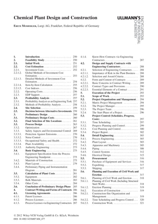
  • 3. is formed, consisting of process engineers, sales engineers, and other engineering personnel. It is useful to appoint a project leader to coordinate the team. Normally, the same person will later become responsible for implementing the project if the decision is taken to proceed. Preliminary studies aimed at defining the objective partly depend on initial economic es- timates and generally include: 1. Market analysis and trend analysis 2. Fixing of production capacity 3. Examination of competing processes and of the patent and license situation 4. Legal aspects 5. Estimation of investment costs 6. Estimation of production costs 7. Estimation of profitability 8. Selection of an appropriate plant location 2.1. Initial Work Market Analysis and Production Capa- city. Before the economically optimum plant capacity is set, a careful market analysis must be carried out. This analysis must be performed by experienced market analysts, even if the product has a comprehensive international sales history. These specialists evaluate literature on the de- velopment of similar products, determine the capacity of existing production facilities, carry out representative surveys, obtain suitable con- ditions from downstream processors in the case of intermediate products, and forecast the future market for the product. They must also provide a realistic evaluation of the competition and the world economic situation. Forecasts of costs for raw materials and working capital play an im- portant role in the economic analysis. A new chemical product usually experiences slow early growth with a relatively high price and low output. The market then expands; production climbs faster and prices drop. Finally, prices stabilize at a low level, and older, smaller plants are shut down (see Fig. 2). If market analysis shows that world output of the product is still increasing rapidly, expansion of capacity through erection of a new plant may have a good outlook if other conditions are favorable. The future price decline must, however, be allowed for in the calculations. In the upper part of the trend curve, invest- ment only makes sense if a clear demand is Figure 1. Development of a project Vol. 8 Chemical Plant Design and Construction 251
  • 4. perceptible in the market. The production curve for the old process may fall off if a new, more economical production process appears. (Exam- ple: low-pressure process for methanol produc- tion forces shutdown of older high-pressure pro- cess.) The new process may open up new markets and lend new impetus to development [1–4]. Competing Processes, Patent and License Situation. The patent and license situation must be investigated at the beginning of the study. Foreign patents may block the construc- tion project if the owner of the patent is not prepared to grant a license (see also Chap. 4). Legal Aspects. Extensive, far-reaching en- vironmental regulations mean that it is essential to make an early approach to authorities that will later have to approve the operation of the plant (see Section 3.3.3.5). 2.2. Cost Estimation If initial planning work has shown that invest- ment is desirable and the market analysis has led to a tentative capacity figure, a first estimate of investment costs and subsequent operating costs is performed. Simply calculating and analyzing the invest- ment costs is not sufficient because, over the service life of a plant, operating costs make up a much greater proportion of life- cycle costs than investment costs do. The goal of cost estimation in the conceptual phase is to optimize the life- cycle costs of a chemical plant. This often means increasing investment costs so as to lower oper- ating costs. Operating costs are favorably influ- enced by long component and equipment life- times, improvements in maintenance and con- sumption, and other factors. Cost prediction as the basis for profitability analysis should there- fore include the determination of investment costs as well as subsequent production and oper- ating costs. The following sections discuss methods of determining investment and operating costs. 2.2.1. Investment Costs A proven technique in investment cost estima- tion is to subdivide the project into onsite and offsite items. Onsite Items. The term onsites denotes all facilities required to make the desired product. Offsite Items. Offsites are all facilities that are normally not located within the process plant. They include facilities for the delivery of steam, electric power, gas, solid or fluid fuels, water, compressed air, and instrument air. Furthermore, this group includes stockpiles and warehouses for raw materials and semifinished and finished products; service facilities (administrative build- ings, canteens, workshops, stores, laboratories, parking, fire protection, roads, tracks, and harbor facilities); and, finally, power plants; loading docks; facilities for treating raw materials, off- gas, wastewater; and waste disposal facilities. In the United States, offsites are usually di- vided into storage and handling (stocks of raw materials and finished products), utilities (gener- ation or delivery of energy as steam, electricity, and water), and service facilities (e.g., offices, recreation rooms, laboratories, workshops, warehouses). On grounds of cost, an attempt must be made to carry out an ‘‘order-of-magnitude’’ estimate at minimal cost. This estimate is of course inexact, but later it makes it easier to decide whether to bear the costs for an accurate analysis. The approximate determination of investment costs is subdivided into simple ‘‘global’’ methods and ‘‘detailed’’ methods. Methods for estimating in- vestment costs are now well-established; those now in use are described in publications mainly dating from 1960 – 1984. Figure 2. Development of a new product 252 Chemical Plant Design and Construction Vol. 8
  • 5. 2.2.1.2. Global Methods of Investment Cost Estimation Global methods permit investment costs to be estimated relatively easily and with an accuracy between Æ 30 % and Æ 50 %. Several methods are outlined below [5]. Single Complexity Factor. In the single- complexity-factor method [6] processes are clas- sified as having a low, medium, or high com- plexity factor. Low Complexity Factor. This class includes all batch processing plants and all processes involving simple syntheses (e.g., production of sulfuric acid). Medium Complexity Factor. This class comprises processes with gas and fluid phases that run at ordinary pressures and temperatures. High Complexity Factor. This class covers processes with high pressures and/or tempera- tures, as well as polymerization processes. Investment costs depend on the complexity factor and the required plant capacity, and are determined from empirical data obtained in other processing plants. Auxiliary and utility units are taken into account by adding 45 %. This method has the advantage that it permits estimation of investment costs in the orientation phase when little information about the process is available. Turnover Ratios. The turnover-ratio meth- od allows costs to be estimated without process information by using market information such as product sale price and sales volume [7]. On the basis of plants already on-stream, a capital turnover ratio is obtained by dividing the annual return on sales by the investment costs. A statistically determined turnover ratio and an expected annual return on sales are then used to estimate the investment costs of new plants. Turnover ratios in the chemical industry lie between 1.2 and 1.5. Statistical turnover ratios can be found for the analysis of individual plants, companies (based on balance sheets and profit-and-loss statements of typical firms), or a whole industrial sector. Degression Exponents. The use of degres- sion exponents (cost-versus- capacity exponents) per-mits relatively accurate cost estimation. The technique is based on costs for plants already on- stream. The exponents are used to estimate in- vestment costs for the planned facility as a func- tion of plant capacity. Investment costs for proces plants are pub- lished from time to time and can be used for initial cost estimation. The costs of identical or similar plants within the same company can be used in a similar way.In 1967, J. E. HASSELBARTH [8] published the costs of process plants for 60 chemical products, including investment costs per tonne of annual capacity. His figures referred to costs within battery limits (i.e., within the plant boundary), exclusive of land and offsite facili- ties. In 1970, K. M. GUTHRIE [9] compiled the investment and operating costs for 54 chemical and refinery processes covering a wider capacity range. The degression exponents cited in both publications allow the calculation to be applied to other capacities. (Example: Given a degression coefficient of 0.7, doubling the capacity leads to an increase in investment costs by a factor of 20.7 ¼ 1.65.) When specific degression exponents are used it should be noted that the error range grows with the capacity scaling factor. This type of calcula- tion generally gives acceptable results only for scaling factors of up to 1: 3. Furthermore, the use of the method depends on the state of the art because changes in processes, apparatus, and mechanical technique can change the exponents. Comparative Methods. When adequate data are available from an existing plant similar to that being planned, the investment costs of the old plant can obviously be used to calculate the costs of the new one. The following information is needed [5]: 1. Production capacity 2. Construction time 3. Investment costs (inside and outside battery limits) 4. Location Costs inside and outside battery limitsare both determined with degression exponents. Cost es- timation outside battery limits must, however, be preceded by a critical analysis of the auxiliary and utility units needed. The figures are adapted to the location by the use of indexes to adjust for the following [5]: Vol. 8 Chemical Plant Design and Construction 253
  • 6. 1. Construction location 2. Economic situation of the industry 3. Taxes 4. Labor market 5. Qualifications of available labor 2.2.1.3. Detailed Methods of Investment Cost Estimation If the preliminary planning as embodied in technical documents has reached an advanced stage, it can form the basis for investment cost estimation that takes into account specific details of the project. Methods used for this are mainly based on analogies with plants that are already on-stream. Detailed methods of plant matching [10] and multiplication-factor techniques of cost determination are emp- loyed. Lang Factor Method. If the process is well characterized, the required capacities of fur- naces, apparatus, and machinery can be specified in preliminary flow sheets [11]. These specifica- tions cover main plant items such as furnaces, columns, filters, reactors, heat exchangers, ves- sels, and machinery. The estimator can determine the costs ‘‘free-on-site’’ for such items or obtain the costs from suppliers. LANG used cost analyses of existing plants to derive multiplication factors that allow determi- nation of the investment costs for process units within battery limits if the costs of the main equipment items are known [12]. The factors depend on the type of plant. LANG distinguishes three types according to the state of aggregation of the raw material and product: ‘‘solid’’ (e.g., ore sintering), ‘‘solid – fluid’’ (e.g., oil – shale re- torting with shale – tar recovery), and ‘‘fluid’’ (e.g., petroleum refineries, petrochemical plants). If the costs for the main plant items are taken as 100, total processing-plant costs are found by multiplying by 3.10 (solid-processing plant), 3.63 (solid – fluid-processing plant), or 4.74 (fluid-processing plant). CHILTON [13] and HAND [14] have improved these approximate Lang factors by introducing supplements to the costs of main equipment items. Estimates of the total costs of a ‘‘grass- roots’’ plant can then be made. Figure 3 outlines the procedure for preliminary calculations by the Lang – Chilton method. Other authors have extended and refined the Lang method. For example, BURGERT in 1979 published an analysis of investment- cost struc- tures for more than 100 projects [15]. In 1965, MILLER [16] devised another system based on modified Lang factors. MILLER assumed that the factors are influenced by three other parameters besides those used by LANG (solid, solid – fluid, fluid): 1. Size of main equipment items 2. Material from which the plant is constructed 3. Pressure for which the plant is built Increasing size, more refined materials, and higher operating pressure increase the relative costs of the main equipment items in relation to storage, utilities, and service facilities, thus di- minishing the factors. According to MILLER, all factors can be referred to the mean per-piece costs of plant parts and depend on these. Guthrie’s Modular Technique. The mod- ular technique published by GUTHRIE [17] in 1968 is also based on LANG’s method and is the best of the multiplication-factor approaches. The project is first broken down into six modules [10]: Five direct modules Chemical processes Solids handling Site development Industrial structures (civil work) Auxiliary and service facilities outside battery limits (offsites) One indirect module Indirect project costs The key costs of the direct modules are deter- mined first. For the ‘‘chemical process’’ module, these might be costs for machinery and equip- ment. As shown in Figure 4, the key costs of the direct modules are multiplied by the gross mod- ule factors. The sum of the individual ‘‘gross module costs’’ gives the investment costs for on- and off-battery facilities. GUTHRIE proposes a variety of methods for calculating the equipment costs of a module. The multiplication factors required for this include not only size of the component (magnitude fac- tor) and the alloy factor, but also indirect effects. 254 Chemical Plant Design and Construction Vol. 8
  • 7. This relatively accurate modular technique has not found wide acceptance, however, because it is relatively difficult to perform the calculation and maintain the statistical data base. 2.2.1.4. Item-by-Item Calculation When detailed methods of investment- cost esti- mation do not give sufficient accuracy, the only alternative is to calculate investment costs item by item. The plant equipment and the engineer- ing work must be specified. The procedure and amount of work required for such a cost estima- tion are the same as those described for calculat- ing plant costs (see Section 3.5). Close coopera- tion between the subsequent operator of the plant and an engineering firm has proved advantageous for this approach. Figure 3. Preliminary cost estimate using factors (Lang – Chilton method) Vol. 8 Chemical Plant Design and Construction 255
  • 8. 2.2.1.5. Cost Indexes The methods of investment-cost estimation dis- cussed above are generally based on historical statistics derived from existing plants. The cost figures obtained by these methods are therefore referred to given periods, such as 1985. If invest- ment costs are to be estimated for the year 1990, the estimates must be adjusted to current prices. Every industrial country publishes one or more indexes for this purpose. Some widely used indexes for the United States and Germany follow: 1. Bureau of Labor Statistics cost index for equipment, machinery, and materials in the U.S. market 2. Chemical Engineering Plant cost index [18–20] 3. K€olbel – Schulze index for chemical plants (K€olbel – Schulze Index f€ur Chemieanlagen) [21] 4. Producer price index for commercial products (Index der Erzeugerpreise gewerblicher Pro- dukte) compiled by the German Federal Sta- tistical Service (Statistische Bundesamt) These indexes are based both on chemical- plant cost structures and on national primary price indexes. Figure 5 compares important cost indexes over time. 2.2.2. Operating Costs Along with the investment costs, the operat- ing costs incurred in the production of a given product also play an important part in deciding Figure 4. Simplified modular concept for estimating investment costs F ¼ net module factor; F2 ¼ gross module factor Figure 5. Development of cost indexes a) CE Plant cost index, 1959 ¼ 100, successively published in [18] (1982 revision of productivity factor from 2.50 to 1.75); b) K€olbel – Schulze index, 1976 ¼ 100, successively published in [19] 256 Chemical Plant Design and Construction Vol. 8
  • 9. whether to erect a plant. The technical and eco- nomic literature, however, contains little infor- mation on the preliminary calculation of operat- ing costs. Possible reasons are the complexity of the problem and the company’s possible loss of maneuvering room if internal operating data were published [22]. The methods of estimating operating costs discussed below are based on data from compa- rable plants or empirical data from plants belong- ing to the same company [22]. They are related, but differ as regards starting information: published data, empirical data, business information, physical data, correlations, and information from comparable plants. In or- der to check the reliability of the results, operat- ing costs should be estimated by several methods so that the calculations can be verified and error ranges given. Graphical Method. The graphical method is based on statistical evaluation of operating costs in existing plants. Operating costs per unit of product are plotted versus plant capacity. It is important to be aware of the scope of the plotted costs. The graph usually includes only the manufacturing costs of a product: raw materials, power, catalysts, chemicals, wages, depreciation, and maintenance. Plant overheads, fixed costs, and indirect production costs should also be taken care of by multiplication factors. Business Analysis. The analysis of bal- ance sheets and profit-and-loss statements from companies that manufacture the product in question as their main commodity may also be helpful. Energy-Based Methods. Chemical produc- tion processes involve large amounts of energy. The chemical reactions themselves often contrib- ute very little to energy requirements but up- stream and downstream operations do. This fact provides the basis for several methods used to estimate operating costs [13], [23–25]. Key Cost Categories. If it is assumed that chemical plants show relatively constant operat- ing- cost structures for a given product, operating costs can be calculated with multiplication fac- tors if a single cost category is known accurately [22]. Scaleup Methods. When operating costs for similar plants are known,specific data can be used to derive scaling coefficients for propor- tional, personnel-dependent, and investment- dependent costs. The operating costs can then be estimated. 2.2.3. EDP Support A number of manufacturers and operators have established electronic data processing (EDP) programs for estimating investment and operat- ing costs. Examples are Factest (ICI) [26] and the ASPEN package [27]. The ASPEN PLUS soft- ware, a flow sheet simulation program, is sup- plemented with a costing module. The program sizes the most important equipment and machinery from the process simulation. Investment costs are estimated by the use of multiplication factors and cost indexes to adjust to current price levels. ASPEN PLUS allows the calculation not only of fixed costs for an investment, but also operating costs. To determine operating costs, the program calculates fixed and variable components sepa- rately. Variable costs include raw materials, fuels, catalysts, disposal, and ‘‘running royal- ties’’. Fixed costs comprise personnel costs for maintenance and operation, overheads, insur- ance, and taxes. The program generates summa- ries and details of annual operating costs. Finally, the software can evaluate avariety of profitability measures (Section 2.3). 2.3. Profitability Analysis 2.3.1. Profitability Analysis as an Engineering Task In profitability calculations, it is necessary to keep in mind that a plant erected without reserves (standby units) for unavoidable shutdowns and repairs will produce for only 330 days (or 8000 h) a year; that is, it will attain only ca. 90 % of rated capacity on a long-term basis. Manufacturers generally rate their equipment for operation at 10 % over capacity. However, this figure only applies to intermittent overloads and is not guaranteed. Vol. 8 Chemical Plant Design and Construction 257
  • 10. If full-load operation is required all year, the plant must not be designed as a single-train (single processing line) facility, unless it is set up for 110 % capacity and adequate storage is provided for the finished product. Large storage areas are needed if sales are seasonal (e.g., fertilizers). Because the feasibility study includes com- parisons between alternative processes, two pro- cesses with equal profitability need not be ranked equally. For example, both may have equal production costs but different fixed costs. Fixed costs usually comprise interest pay- ments and operator wages. Nearly all other costs depend on output and are therefore variable (e.g., costs of raw materials, power, and fuel). If market conditions make it necessary to reduce the output to, say, 80 % of rated capacity, the plant with high fixed costs will become unprofit- able more quickly. Thus, in the case of two equally profitable plants, the plant with the lower fixed-cost contribution will be preferred. High fixed costs often have to be accepted, if the need for reliable operation dictates that critical parts of the plant must be designed with 100 % standby capacity or the plant must be subdivided into parallel trains. The profitability calculations must take into account that 2 – 2.5 years usually elapse be- tween the start of planning and the commission- ing of the plant. Interest therefore has to be paid on design and construction costs. Working capi- tal is also needed for storage of raw materials and product. Finally, for technical or market-related reasons, a period of 6 – 12 months generally elapses after commissioning before the utiliza- tion of the plant is sufficient to cover the costs (break-even point). Only then does the return flow of capital begin. The history of an investment is illustrated schematically in Figure 6. 2.3.2. Methods of Profitability Analysis Methods for assessing the profitability of a proj- ect [1, pp. 285 – 401], [28–33] differ in the way investment, revenue, and risk are associated. The three most important techniques are described briefly below. These profitability calculations are combined and linked with operations research techniques [34], [35], so that alternative proposals can be obtained with a justifiable amount of effort. Payout (Payback) Period. If alternatives are only to be compared, it may be adequate to divide invested capital by gross excess revenues (proceeds from sales minus operating costs). This method gives a quick indication as to whether the investment is attractive. If, for example, a value of 3 (payout period 3 years) or less is obtained, the investment should be profitable. This does not mean, however, that the plant will be completely written off after three years on stream. A more realistic figure can be obtained by including taxes and interest under expenses and listing revenues by year after commissioning (higher operating costs in the first year when full capacity has not been reached, future decline in earnings). Return on Investment (ROI). In large chemical companies, investments depend not so much on the payout period but on whether the investment will increase total profits, i.e., divi- dends to the stockholders. Thus a large company will only invest if a certain return on invested capital is ensured. The ROI method is employed in such cases. The annual profit before taxes and interest, but after depreciation, is divided by the invested capital. In contrast to the preceding method, startup losses are neglected and data for design- capacity operation are used in the Figure 6. Schematic showing the course of capital investment a) Accumulated profits; b) Return on investment; c) Total production costs (fixed and variable); d) Fixed costs; e) Ac- cumulated cash flow 258 Chemical Plant Design and Construction Vol. 8
  • 11. calculation. The result is a pretax rate of return on invested capital. Dynamic Calculations are based on the discounted cash flow (DCF) method. The DCF method is an advance over ROI. It allows for the fact that investment costs precede revenues. Since only funds existing at the same time can be compared, all revenues and expenses that are directly or indirectly related to the project from the start of planning onwards are discounted to a fixed time, usually the start of production. A rate of return is then sought that makes the sum of the discounted annual excess revenues equal to the cash value of the total investment at the start of production. Since excess revenues are spread throughout the entire year, they are all recalcu- lated to the middle of the year and discounted from then on. The calculation runs over the economic life of the project, but usually only 10 years, since the longer-term market position can scarcely be foreseen. Furthermore, the equiv- alent value of revenues after more than 10 years is so small that it has little effect on the result (internal rate of return). 2.4. Site Selection The selection of an optimal site is a high-priority item in the feasibility study. Every economic region has its advantages and disadvantages. The present and future importance of correct site selection can scarcely be overstated. Wrong site choices cannot be corrected later and have led to the downfall of many companies. The development of world trade and the de- cline of tariffs have changed the environment of many existing plants for the worse. Formerly, for example, the steel mill was located near the coke plant and iron ore transported to it. Today, the most important Japanese steel mills are located on the coast and import coal and ore from over- seas. Petroleum refineries used to be sited at petroleum sources. Now that giant tankers and pipelines have come into wide use, refineries are often located in consumption centers. Many large chemical companies are now in- vesting in coastal and foreign property. Good surveys of publications important in site selection can be found in [1, p. 439], [36–38]. STOBOUGH has devised a selection system, based on a point ranking, which allows unsuitable sites to be elim- inated quickly. The short list of remaining sites should then be examined as described below. Site Quality, Topography, Soil Conditions, Climate, Flood Risk. The short list should in- clude only locations that appear suitable for the plant and possible subsequent expansions from the standpoint of size, price, transportation facil- ities, and buildability. If the terrain is not flat, it should be established whether grading or filling is necessary and whether piles must be driven for foundations. If transportation facilities (roads, railroad tracks, water routes) are lacking, the expense of devel- oping them must be ascertained. Only costs for developed sites can be compared. Raw-Material Availability Including Power, Fuels,andWater. Rawmaterialsofgood quality must be available at a favorable price throughout the service life of the plant. Other prerequisites are availability of sufficient fresh water, electric power, and fuels. Obtaining power and steam on a grass-roots site can be expensive. Environmental Conditions, Environmental Legislation, and Infrastructure of the Con- struction Site. Improved roads, rail connections, and location on harbors or year-round navigable rivers are important criteria. Long-Term Availability of Qualified Labor. In developing countries, leading person- nel – from foremen to management – must meet very stringent requirements. Only after years of schooling will local personnel have the required standard of education. Raw-material costs, wages, and maintenance costs are also crucial in site selection. Finally, it must be taken into account that the phase of startup losses will be longer if an industrial site has to be developed from scratch. 2.5. Decision between Alternative Investments Preparation for Decisionmaking. Large investment projects involve exploration of wide- ly varying options. In addition to straight profit- ability analysis, qualitative factors should also be considered (e.g., special site problems, political environment, market development). These qualitative factors involve risks, which must also be assessed. The preparation phase for Vol. 8 Chemical Plant Design and Construction 259
  • 12. decisionmaking therefore includes not only cal- culation of investment and operating costs, but also risk and sensitivity analysis [39]. Risk Analysis. In risk analysis, all constraints that can have an adverse effect on life- cycle costs and earnings must be identified, documented, and assessed. These include: 1. Estimation of sales market 2. Energy cost development 3. Availability of raw materials 4. Plant construction risks 5. Management-related risks (e.g., site-depen- dent problems, reliability of vendors and subcontractors) 6. Organizational risks The financial effects of the identified risks are quantified by experts in risk-assessment proce- dures and the results then evaluated in a Monte Carlo simulation [39]. Sensitivity Analysis. Sensitivity analysis should be carried out to find out how the profit- ability and risk situation changes when certain assumptions and constraints are varied. For ex- ample, it might be asked how much the invest- ment costs would have to be reduced to allow the desired profit and an acceptable amortization. A calculation of annual revenues based on the quantity of product that can be sold in the market and its price allows a variational calculation of this type to be made. The expected profit is deducted from the sum over the project life. The remainder represents the maximum available investment and operating costs that have to be optimized in several steps. This approach is called ‘‘design to cost.’’ Investment costs are often minimized in this ap- proach by designing low- cost plants (usually open-air plants with simple equipment and no storage capacity for intermediate products). Several iterations are usually required to reach an optimum between investment costs and oper- ating costs. Decisionmaking. Profitability, sensitivity, and risk analyses may lead to the conclusion that execution of the project is not desirable. Recent publications may have already shown that similar projects undertaken by third parties will oversat- urate the market. Other companies may have access to such good raw-material sources that the company considering the project cannot com- pete. It may be that environmental regulations have a prohibitive effect on costs. The planning work should then be stopped until new informa- tion or analyses suggest a different conclusion. The avoidance of huge losses on a badly planned facility far outweighs the costs incurred up to this point. If, however, the feasibility study reveals a positive situation, the next step is to incorporate the capital requirement into the company’s in- vestment program and give the go-ahead to start preliminary design. 3. Preliminary Design The following results from the feasibility study provide the basis for deciding to proceed to the preliminary design phase: 1. Plant capacity has been set on the basis of market research 2. The choice between expansion of an existing facility and construction of a new one has been made 3. The list of potential sites has been shortened to two or three alternatives 4. The projected capital outlay has been determined 5. The projected production costs for the product have been determined 6. The payout time and profitability have been estimated The main task in preliminary design is to obtain a more exact calculation that takes into consideration all costs up until commissioning. The first step toward this objective is to work out the engineering details. A qualified project leader directs the prelimi- nary design. Specialist engineering teams (e.g., for process calculations, equipment design, plant layout, and estimations) provide advisory sup- port [40]. 3.1. Preliminary Design Costs The funds and time spent on preliminary design can be considerable, depending on how pre-cise planning and budget are to be. Although highly 260 Chemical Plant Design and Construction Vol. 8
  • 13. accurate results are always sought, technical documentation and calculations should be re- fined only to the degree necessary for subse- quently deciding whether to implement the proj- ect. Events during the preliminary design period may force the abandonment of the project. If the feasibility study predicts very favor- able profitability, less accurate calculations (say Æ 20 %) may be acceptable; if the project is expected to be marginally profitable, better accuracy (e.g., Æ 10 %) is needed. Figure 7 [41] shows the basic information required for given accuracy levels. Even if the upper and lower limits of the percentage ranges in Figure 7 are made equal, the probability of exceeding the projected costs is greater than that of falling short of them. This is primarily due to subse- quent additions that are not known at the time when the calculation is performed. A ‘‘contin- gencies’’ item is therefore commonly included in the calculation. Design costs for preliminary calculations at various accuracy levels, according to the Ameri- can Association of Cost Engineers [42], are pre- sented in Table 1. Specific empirical figures are given in [43]. Preliminary design requires a special project team consisting of persons with the necessary expertise. A chemical company whose engineer- ing staff is oriented mainly toward maintenance and the occasional addition of new pieces of equipment should not attempt to perform the preliminary design of a large plant or a branch plant in-house. Such a department lacks appro- priate experience and is also short of capacity. The need to hold down design costs and maintain the performance level of in-house engineering staff on their specific tasks, forces even large chemical firms to collaborate closely with exter- nal engineering contractors who will later be in charge of executing the project. External engi- neering firms usually offer cost advantages be- cause they have so much experience in their routine fields that they can quickly estimate reliable cost figures for projects based on well- known processes. The client’s role is limited – at least as far as established processes are concerned – to making process knowhow available, purchasing li- censes, and cooperating with the engineering contractor in customizing the plant to relevant requirements. Contract forms have been developed for the collaboration between the customer and the en- gineering firm in the basic-design and/or detai- lengineering phases, as well as for procurement, supply, construction, construction supervision, and commissioning (Section 4.2.2). Another option for cutting design costs is for the chemical firm to obtain a process license, with the licenser providing the complete ‘‘basic design.’’ 3.2. Final Selection of Site Locations After the feasibility study two or three suitable sites are often available for the new plant. A final decision can be made only after detailed study. If the potential sites are close to the client’s parent plant, similar fringe conditions can be assumed to apply for the purpose of site compar- ison.If, however, abranchplant is to be erected in a foreign country, conditions are usually differ- ent which means that each of the alternatives has to be carefully analyzed. Important constraints besides those already listed in Section 2.4 include: 1. Medium- and long-term capacity of the local (national) market to absorb the product 2. Export to nearby countries 3. Availability, quality, and price of raw materials 4. Political situation and risks (e.g., risk of nationalization) 5. Tax laws, tariffs, possibility of repatriating profits If, for example, one country has cheap raw materials but a limited capacity to absorb the product, partial upgrading of the raw material and fabrication of intermediate products should be considered. Manufacture of the end product would then take place where there is adequate long-term demand and a suitable distribution network. A team of the client’s experts should perform a thorough on-site examination of each alterna- tive before the final decision is made; close contact with national and local government agen- cies is important. The recommendations of this team should weigh heavily in the choice of site. Vol. 8 Chemical Plant Design and Construction 261
  • 14. Figure 7. Accuracy of cost assessment based on available information [41] 262 Chemical Plant Design and Construction Vol. 8
  • 15. Partnership with qualified domestic enter- prises is becoming increasingly popular (e.g., joint ventures). 3.3. Process Design See also ! Process Development, 1. Fundamentals and Standard Course The feasibility study defines the process objec- tive, i.e., it specifies products (type and quantity), feedstocks and auxiliaries (type and quantity), and local conditions (environmental situation, elevation, climate, energy situation). This objec- tive, together with the overall state of the art and the experience of the operater, licenser, or plant design and construction contractor, provide the basis for process selection. Process selection can be done most simply in the form of a block flow diagram (Fig. 8), in which each block represents a unit operation or, in complex plants, a plant section containing Table 1. Design costs for cost estimates [43] Type of estimate Synonymous terms Accuracy, % Costs as percentage of project value Order of magnitude estimate ratio estimate Æ 30 – Æ 50 0 – 0.1 seat of the pants estimate ballpark estimate guesstimate Study estimate evaluation estimate Æ 20 – Æ 30 0.1 – 0.2 predesign estimate factored estimate Preliminary estimate sanction estimate Æ 10 – Æ 25 0.4 – 0.8 funding estimate authorization estimate budget estimate Definitive estimate project control estimate Æ 5 – Æ 15 1 – 3 Detailed estimate tender estimate Æ 2 – Æ 5 5 – 10 contractor’s final cost estimate Figure 8. Block flow diagram (olefin plant) Vol. 8 Chemical Plant Design and Construction 263
  • 16. several unit operations. The blocks are joined by lines representing the principal material and energy streams. The first step in process design is to establish the operating parameters for the major stages in the process: 1. In the case of chemical reactions, the pres- sures, temperatures, concentrations, reactor type, and reactor size are defined or estimated on the basis of the reaction kinetics and experience gathered in existing plants 2. In the case of mixing (stirring, gas disper- sion, suspension) or separation (distillation, drying, precipitation, filtration) of sub- stances, the pressures, temperatures, con- centrations, and type and size of apparatus are defined or estimated on the basis of established rules. If information needed for setting the operat- ing parameters or designing reactors/apparatus is not known, it must be obtained in bench or pilot-plant tests or calculated approximately on the basis of similar reactions or unit operations. The unit operations used in process engineer- ing are described in [44–49]. Process Flow Diagram. The next step is to prepare a process flow diagram from the block flow diagram. Standard symbols (e.g., defined in DIN 28 004) are used to represent reactors and other apparatus, including equipment for con- veyance and control of important streams. In complex plants, it may be necessary first to prepare a synoptic flow diagram (Fig. 9) and then to draw up individual flow diagrams, giving the needed detail for plant sections and auxiliary operations. Determination of Final Process Data. When the desired effective operating time per year has been set (e.g., 8000 h, corresponding to 91 % availability), the design capacity of the plant (i.e., the mass throughput per unit time) is defined. The next step is to compile the specifica- tions for all feedstocks, auxiliaries, catalysts, utilities, and end products, and to estimate what intermediate products are to be expected. These specifications include relevant physical and chemical properties as well as the battery-limit states of all substances received and shipped. On the basis of the process flow diagram, the preliminary process parameters, and the above- mentioned specifications are used to prepare material and energy balances for the process steps and finally for the entire process. This objective is not generally achieved in a single set of computations. The experienced process engineer must use an iterative procedure to mod- ify the process flow diagram and/or the process parameters so that a closed material and energy balance is attained as simply as possible. The following must always be ensured: 1. Compliance with emission limits. 2. Plant safety (i.e., adequate margins of safety relative to critical operating conditions). 3. Maintenance of product quality. 4. Control of startup operations and of planned and unplanned shutdowns. This includes specification of components and media re- quired (e.g., heatup burners, cooling and purge gases, and pressure-reducing valves). These calculations must also take account of long-term effects, such as increasing contamina- tion (resulting in a higher pressure drop and less efficient heat transfer) or aging of catalysts (lower conversion, changes in temperature and concentration profiles). The calculations give mass and energy values for all important points of the plant, preferably downstream of each unit operation. The mass and energy flow rates and the final process parameters are tabulated at the foot of each process flow diagram and keyed to points in the plant (Fig. 10). The preliminary sizes of the reactors and apparatus are now checked and, if necessary, modified in the light of the final process parameters. If a plant is to be operated at reduced capacity for short or long intervals, appropriate calcula- tions must be performed. If unacceptable operat- ing conditions or bottlenecks are found in certain plant sections, additional measures must be taken (e.g., supplementary heating, gas recycle, or the partial shutdown of some unit operations). A similar treatment applies when occasional over- loading of the plant is expected. Other factors are then determined, namely the quantities of substances that have to be available 264 Chemical Plant Design and Construction Vol. 8
  • 18. for the initial charges and the storage capacities (including those outside the battery limits) need- ed for feedstocks, auxiliaries, intermediates, and end products. Finally, a detailed process description is writ- ten. Assessments of known processes are avail- able on a subscription basis from Chem Systems Inc. and SRI International. A survey of produc- tion processesfor initial and intermediate organic products is given in [50]. Process Simulation. Process design calcu- lations for multistage, interconnected processes with material and energy recycle soon become Figure 10. Individual process flow diagram for a plant section a) Heat exchanger; b) Purification tower; c) Control valve; d) Block valve; e) Steam trap; f) Blind; g) Control loop (temperature, pressure, flow) 266 Chemical Plant Design and Construction Vol. 8
  • 19. very complex. Computer tools enable designers to develop key concepts in a reasonable time and thus to optimize the process according to certain criteria (investment cost, yield, energy economy, production costs). ‘‘Flow sheeting’’ programs are complicated computer programs that model unit operations mathematically and allow them to be interconnected. A plant can thus be represented as a network of unit operations with material and energy streams and thus simulated [51], [52]. The material and energy balances can be calculated as functions of the process parameters. An iterative procedure can be carried out to bring the balances to equilibrium for individual and interconnected unit operations. Simulation programs are available for steady- state operation and dynamic conditions (e.g., ASPEN PLUS, DESIGN II, PROCESS, HYSIM, and SPEED UP). Design calculations for reactors and other equipment (e.g., heat exchangers) can be per- formed with special-purpose design programs and process simulation packages. The program for a fired tubular furnace (e.g., steam reformer) allows calculation of process conditions as a function of the configuration and geometry of the tubes, bur- ners,andcombustionchamber.Animportantfunc- tion of such programs is to simulate the equipment when connected into systems and to identify and remedy bottlenecks (de-bottlenecking). Process simulators have integrated substance data bases that meet the needs of most applica- tions. Further data can be obtained from data bases [53] and compilations of physical and chemical data [54–56]. Proprietary data and em- pirical factors (interactions, long-term effects) can also be input. 3.3.2. Optimization The object of plant optimization is to obtain an optimal economic result. This is a continual problem during the operation of a plant, espe- cially if its capacity is diminished by aging or increased by expansion, or if product earnings, costs, or expected profits change during its life- time. The parameters necessary for subsequent optimization must, if possible, be established in the design stage. They relate to process design, the plant concept, the selection of equipment, and the process control system. The operating result is primarily determined by product earnings, expected profit, and costs. Obviously, costs decrease with longer plant ser- vice life and higher availability. The feasibility study should provide data about both of these factors. Most chemical production facilities are oper- ated around the clock. Since fixed costs represent a significant proportion of the operating costs (interest payments, personnel, energy supply, overheads), high availability is essential for an optimal result and is often more important than maximal process optimization. Single-train plants with many unit operations in series are more susceptible to breakdowns than plants in which the critical sections are multi- trained or have standby equipment. The draw- back of a larger capital investment must be weighed against the advantage of a higher ex- pected availability. In established methods of risk analysis, the plant concept is systematically analyzed on the basis of process flow diagrams, process descrip- tion, equipment lists, and operating experience (e.g., reliability and maintainability, RAM). An initially higher expenditure on equipment not only results in better availability but also lowers repair and maintenance costs. Optimization of process engineering must then be investigated. The process design ob- jective of a unit operation or a plant can be achieved with various combinations of capital costs and variable production costs (feed- stocks, auxiliaries, utilities, energy consump- tion, disposal) as the following simplified examples show: 1. In plants with high gas throughputs, the cross- sectional areas of piping, fittings, and reac- tors/apparatus determine the pressure drop in the plant and thus the energy that must be expended to transport the gaseous media. Large cross sections, with correspondingly higher capital costs, lead to lower energy costs and vice versa. 2. In heat exchangers, such as those used for waste-heat recovery, the quantity of trans- ferred heat increases with increasing ex- change area (¼ higher capital costs) and in- creasing flow velocities (¼ higher pressure drop ¼ higher energy consumption) and vice versa. Vol. 8 Chemical Plant Design and Construction 267
  • 20. In each case, there is an optimum for given economic parameters. The second example is more complicated, because not only must the cost optimum for a given quantity of heat be determined but also the optimal quantity of heat to be exchanged. It must further be taken into consideration that the cost of waste-heat transfer to the environment decreases when more heat is recovered. Similar examples could be cited for the opti- mization of conversions, the optimization of the product mix when products are coupled, and the simultaneous minimization of byproducts and residues and of their reprocessing or disposal. The examples lead to the following conclu- sions: identical plants do not have a unique optimum; instead, they have a variety of optima that depend on the crucial technical and econo- mic constraints of a given site location. Optimal design of the plant is based on economic para- meters employedin the designphase.Subsequent deviations may partly offset one another or may accumulate in the result. The objective is thus to assign cost factors to the functional dependences of the process design or, in mathematical terms, to express the depen- dence of the costs on the engineering variables in the form of a cost function. Limiting parameters always have to be introduced, e.g., emissions, plant reliability, product quality, and safety fac- tors for equipment and material (to ensure maxi- mum lifetime and on-line time). Optimization can be solved by a suitable method (linear and nonlinear optimization, mixed-integer program- ming, gradient and search procedures). The large number of variables in a plant design and the high degree of interaction in plants with many process loops mean that a facility cannot be completely optimized during the de- sign phase. The dimensions of such a program exceed any reasonable and justifiable computer effort. It is useful to begin by performing an eco- nomic – technical analysis of the process based on the ‘‘standard design’’ (not yet optimized). This analysis reveals the process stages in which significant fractions of the costs are incurred, consumed, or transformed, and expresses them as a proportion of the total costs. As a rule, a few key points dominate the economics of the entire plant. Optimization work can thus be facilitated right from the start. If individual cost items in subsequent operat- ing periods are expected to deviate significantly from the values chosen initially, new calculations can be made for the few key points, taking maximum and minimum values (sensitivity analysis). A practical application of this method is the comparison of designs ‘‘on an evaluated basis.’’ The costs for the necessary capital (often with allowance for the expected return on investment and tax considerations) and for capital goods are represented in a formula. The actual require- ments for capital and capital goods are substitut- ed into the formula. The lowest resultant value identifies the best concept for the selected pre- mises. Details of cost structure and financing need not be known. Optimization of Individual Tasks. For the calculation of various reactor types, see ! Mathematical Modeling and ! Model Reactors and Their Design Equations. Enthalpy – temperature (H/T ) diagrams and exergy analysis (formerly also availability anal- ysis) are being increasingly used in conjunction with simulation programs to optimize the energy economy of the plant [57]. This is especially worthwhile for processes with high heat turnover or high compression ratios. Apparatus costs must be determined separately. The design of heat-exchanger networks is based on analysisof the heat fluxes in the network as a whole. One representative of such methods is the Linnhoff ‘‘pinch’’ method, see ! Pinch Technology. This technique uses the H/T dia- gram with cumulative curves for the quantities of heat dissipated and absorbed in various sections of the plant at defined temperatures. The method can be applied to utility systems and to the integration of thermal engines [58]. Software is available for the design of heat-exchanger net- works by this method (e.g., HEXTRAN and ADVENT). An alternative method for heat-ex- changer/utility networks is based on the mixed-integer method [59]. Synthesis-gas processes offer an example of integrated loops. These reactions are mostly exothermic, and an attempt is made to transfer the excess heat of reaction to steam instead of cooling water. Use of waste heat from gas production to supply the heat required for gas purification and converting processes has led to 268 Chemical Plant Design and Construction Vol. 8
  • 21. a variety of integrated loops with significant reductions in operating costs, for example in ammonia and methanol synthesis and in the production of nitric, sulfuric, phthalic, and maleic acids. Another optimization possibility is the use of heat pumps. The mechanical compression of vapors and their condensation at higher pressure offers interesting solutions with relatively low investment costs, for example in the distillative separation of components with similar boiling points (e.g., such as ethylene – ethane and pro- pene – propane). The operability and economics of integrated loops must be checked during process design. This can be done by using LINNHOFF’s method of heat integration analysis [60], [61]. Process Synthesis. The development of op- timal combinations of unit operations is an itera- tive process that is now carried out with the aid of simulation programs. An advanced program per- forms computer-aided process synthesis by au- tomatically generating design variants and se- lecting the best ones under consideration of uncertain data, i.e., when material properties, thermodynamic data, and kinetics of partial pro- cesses are incomplete. Results can be applied to some practical problems [62–64] especially to heat-exchanger networks (HENs) and utility systems. The design of separation processes is much more difficult because of the great number of species present. Process synthesis has therefore not reached a comparable level. A survey of the design of column cascades appears in [65]. Optimization has to be customized for every application, key points can be identified only by economic and technical analysis of a process. The boundaries between ‘‘routine’’ optimization during process design and a special, supplemen- tal optimization study are not clearcut. The practical operability of a plant should never be ignored. Overly complicated circuits, highly complex control systems, dewpoints and corro- sion limits that are too close together, and in- creased maintenance costs can all wipe out cal- culated cost savings. Continuous optimization is needed through- out the service life of a plant. Digital process monitoring and control systems allow appropri- ate data acquisition, storage, and archiving. Process data processing systems print data in the form of diagrams, graphs, and tables. They are an indispensable aid in the commissioning and optimal operation of plants. Process-based simulation programs allow on-line and off-line balancing and prompt detection of abnormal occurrences. 3.3.3. Safety Aspects and Environmental Control In the following section the essential elements of safety and environmental control are treated – relevant to the design and construction of a chemical plant, using Germany as an example. The laws and decrees cited are only valid in Germany, however, there are similar laws in other countries, e.g., those issued by the EPA and OSHA in the United States and the ‘‘Stoom- wezen’’ in The Netherlands. The materials present in a chemical plant, their processing, and processing equipment con- stitute a source of risk to persons and property in the plant area and its surroundings. The level of risk depends on the nature, extent, and probabili- ty of occurrence of injury or damage [66]. Safety engineering institutes measures that reduce (lim- it) the risk to a degree acceptable to the public require that: 1. Potential hazards must be identified 2. Effective safety standards against these ha- zards must be established 3. The standards must be transformed to engi- neering and/or management safety practices 4. It must be proved that the safety level meets requirements 5. The effectiveness of the adopted measures must be evaluated and improved [67] Safety-related functions are the responsibility of governmental supervisors, the plant operator, and the engineering contractor. In approving the plant, the regulatory authorities not only ratify the safety objectives but also evaluate the scope and quality of the safety measures. The operator is responsible for correct execution of these measures. The design and construction firms must assist the operator in complying with the standards [68–70]. Vol. 8 Chemical Plant Design and Construction 269
  • 22. 3.3.3.1. Protection Against Emissions The following important environmental protec- tion goals are necessary for the approval of a new plant and are therefore the concern of authority engineering: Landscape and Surroundings. The erec- tion of a plant on a site not expressly intended for industrial use can run into difficulties [71]. It is also necessary to clarify in advance what effects the plant will have on nearby residential areas and what levels of emissions and noise are acceptable in industrial areas [72–75]. The appearance of the plant must be appro- priate for the surroundings. This factor is gov- erned by restrictions on building height, design, materials, color, the construction of visual bar- riers, and landscape plantings. Air Pollution. Pollution control begins with the classification of hazardous substances and prevention or minimization of emissions to the atmosphere. Release under normal operating conditions is prevented by using appropriate design and process conditions (e.g., gas collec- tion and recovery systems, use of low-polluting burners, catalytic gas purification, use of high- quality flange connections and seals) [76–78]. Safe operation of a chemical plant must be ensured to prevent or minimize the hazard to the surroundings. Possible sources of danger (acci- dents) include release of large amounts of haz- ardous substances (gases, liquids, solids), fire in the plants, and explosions [72]. Safety aspects must be taken into consider- ation in process design, plant layout, and equip- ment selection; in the construction, operation, and maintenance of the plant; and in the training of plant personnel [69]. The ‘‘hazard and operability study’’ (HAZOP) is often used and can reveal weak points in plant equipment and operation while the facility is still under design. This method of risk analysis has been proven in years of use [79–81]. Wastewater. The wastewater generated in a plant is collected and treated in systems classified according to water quality (e.g., severely con- taminated, moderately contaminated, uncontam- inated, rain water). If the systems are properly designed, the treated wastewater can be released into a system approved by the local authority [82], [83]. Wastewater produced in case of fire (fire fight- ing water) must be collected in a retention basin whose capacity is usually sufficient to hold the waterusedin1 hagainstthedesignfire- case[84]. Soil. Soil protection is afforded by sealing all plant areas that might be contaminated by hazardous liquids or solids under normal operat- ing conditions or in an accident [85]. Waste. ‘‘Waste’’ denotes all those sub- stances and parts that cannot be recycled to the production process or otherwise reused. As early as the process selection step, special attention must be paid to waste prevention be- cause waste is difficult to dispose of. In large chemical complexes, wastes from one process can often be used as feedstocks in other proces- ses. This alternative should be investigated close- ly in feasibility studies performed at a very early stage of the project [86–88]. 3.3.3.2. Noise Control The primary objectives of noise- control design are in compliance with contractual and legal provisions while ensuring that the plant is easy to maintain and runs economically. Noise can be controlled at the source by selecting low-noise products and processes. Low-noise equipment often has the welcome side effect that it offers low energy consumption and longer service life. Basic concepts and research in acoustics are discussed as examples in [89–92]. Regulations. Noise- control regulations are intended to protect the surroundings and the plant personnel. Protection of the Surroundings. The basis for immission noise limits in Germany is the Bundes-Immissionsschutzgesetz (Federal Im- mission Control Act) and the TA L€arm (Engi- neering Directive on Noise Control) contained in it [93]. The directive lays down permissible immission noise levels as a function of land use (Table 2). The site of measurement varies; as a rule, it is 0.5 m in front of an open window of the residence. Regulatory practice has been to treat the permissible levels cumulatively: if several 270 Chemical Plant Design and Construction Vol. 8
  • 23. plants emit to one receiver, the maximum level must be distributed among all the emitters. Fur- thermore, if a plant is expanded, its permissible noise-level contribution must not be exceeded. This approach ensures that the permissible total noise level in the residential area is not exceeded. On the other hand, new plant sections are only approved if they meet strict noise standards. Protection of Plant Personnel. The basis for noise regulations at the workplace in Germany comprises the Arbeitsst€atten Verordnung (Work- place Regulation) [94] and the relevant sections of the Unfallverh€utungsgesetz L€arm (Accident Prevention Code) [95] which contain references to DIN standards and VDI guidelines. These regulations set a maximum personal noise level of 85 dB(A) for an 8-h shift and recommend the use of personal hearing protection above 85 dB (A). Personal hearing protection must be worn at levels over 90 dB(A). The most important regulations for plant de- sign follow: Measurement of noise at DIN 45 635 part 1, machines and following parts Average level and assessed level temporal fluctuating sound processes DIN 45 641 Sound propagation in the open VDI 2714 Assessment of working noise in the neighborhood VDI 2058 sheet 1 at workplace regarding danger to hearing VDI 2058 sheet 2 with regard to various occupations VDI 2058 sheet 3 Sound projection from industrial construction VDI 2571 Noise from piping VDI 3733 Noise abatement for ventilation and air conditioning plants VDI 2081 Personal soundproofing VDI 2560 Soundproofing by mufflers VDI 2567 Soundproofing by shielding VDI 2720 sheets 1 þ 2 Soundproofing by metal cladding VDI 2711 Design. The engineering firm must guaran- tee compliance with noise regulations at the workplace and in residential areas. The contract should also stipulate the type of noise measure- ment and the operating conditions at the time of measurement. Planning for noise control begins in the pre- liminary design phase and continues through basic and detail engineering. The engineer must carry out the following activities: 1. Calculate the permissible sound level for the entire plant on the basis of the maximum level allowed in the residential area and available studies on the workplace noise- level limits. 2. List noise-producing components and estab- lish their permissible sound levels. Noise- protection practices are dictated by practical and economic considerations. 3. Prepare noise specifications (including per- missible sound levels) as part of the bid specifications for all noise-emitting equipment. 4. Check the bids (e.g., for machinery, control valves) to ensure that noise requirements are satisfied. 5. Compile specifications for silencers, hoods, and insulation; check bids and orders for these items. 6. Compile noise specifications for the building. 7. After the design is complete, write a design report on residential and workplace noise levels. 8. Inspect installation of equipment at the con- struction site. 9. Measure noise levels of noise-generating equipment at the workshop where it is man- ufactured, and also later when it is installed in the plant and the plant is on stream. 10. Prepare a final report. Manufacturers of noise-generating equipment have many ways of reducing noise. Examples follow: Electric motors: Reduction of cooling air re- quirement, use of low-noise cooling fans, use of improved insulation. Control valves: Division of large-expansion cross sections into smaller areas (perforated Table 2. Permissible noise immission levels Type of builtup area Standard value, dB(A) Day Night Exclusively industrial utilization 70 70 Mainly industrial utilization 65 50 Equal housing and industrial utilization 60 45 Mainly housing areas 55 40 Exclusively housing, health resorts, and hospitals 50 35 Vol. 8 Chemical Plant Design and Construction 271
  • 24. cage), division of pressure release into multi- ple stages, optimized flow control. Air coolers and small cooling towers: Reduction of rotor peripheral velocity, modification of blade profile, increase in number of blades, use of low-noise gears. Pumps: Optimization of impeller design, avoid- ance of cavitating conditions, reduction of impeller peripheral velocity (below 45 m/s). Steam generators and process furnaces: Low- noise, forced-air burners; use of ceramic-fiber linings on interior walls. Compressors: Frequency- controlled drives, low-noise oil systems, direct drives (no gears), low-noise surge-limit control. Important secondary practices of noise abate- ment include: 1. Soundproof enclosures 2. Soundproof hoods and barriers 3. Soundproofing insulation on piping, ducts, and machine housings 4. Silencers in the form of absorbers, resonators, or combinations of both types In most chemical plants, on-battery sound pressure levels can be held to 85 dB(A) by means of careful design. Large compressor sections are an exception; levels up to 100 dB(A) can be expected and such areas must be designated as high-noise areas. Investment costs for noise control normally range from 0.5 to 3 % of total plant material and installation costs. These percentages are ex- ceeded if residential restrictions make it neces- sary to enclose the entire plant. Plant safety and reliability must not be im- paired by noise- control measures. Low-noise machines must therefore be preferred over loud machines with soundproof enclosures. If hoods or enclosures cannot be avoided, accessible areas inside noise enclosures on gas-handling devices must be provided with adequate ventilation, gas alarms, and possibly fire fighting systems.Noise- control barriers and shielding must not block escape routes. 3.3.3.3. Occupational Safety and Health The principal requirement in occupational safety and health is that physiological and psychologi- cal burdens on the employees caused by working and other conditions must be limited to a gener- ally accepted level. Measures must also be taken to prevent or control risks in case of an accident [70]. The occupational safety and health authorities have defined general conditions for ventilation, lighting, and ambient temperatures at work- places, protection against weather and noise, and the safe use of traffic routes inside the plant. Accident insurance regulations are especially important for plant layout and process design of chemical plants. These rules concern: harzardous operations, work involving hazardous substances [77], [78], use of special auxiliary equipment, and ergonomic design of the workplace [96]. Suitably equipped ‘‘social’’ facilities such as rest and changing rooms, washrooms, toilets, and medical stations must also be included in the design [94]. Warning of unavoidable dangers must be given, and appropriate protective measures must be instituted (e.g., signs marking fire or explosion hazard zones and appropriate safe- guards against ignition). Escape routes and protected areas with emergency lighting, fixed personal protection facilities (emergency showers), and alarm systems must be provided [94], [97]. Appropriate layout of buildings and apparatus or enclosures around particularly dangerous equipment help to minimize injuries and damage [96]. Effective fire fighting measures include short access routes as well as fixed or mobile fire- extinguishing equipment with an assured supply of extinguishing media and an adequate action radius. Occupational safety and health measures also apply during construction of the plant. They relate to the structural design and size of the plant and the construction methods. As much as possible of the equipment used in subsequent normal operation of the plant must be available during commissioning for protection of the workers [96]. 3.3.3.4. Plant Availability Capacity and profitability calculations for a chemical plant are normally based on 8000 h/a on-stream (corresponding to roughly 330 d/a). 272 Chemical Plant Design and Construction Vol. 8
  • 25. Shutdowns are generally planned at intervals of one or two years to allow cleaning of heat exchangers, apparatus, and piping; charging of new catalysts and chemicals; replacement of worn mechanical parts; and prescribed inspec- tions by regulatory authorities. Unplanned shutdowns are usually caused by mechanical defects or automatic emergency shutdowns when operating parameters are out- side the limits for normal plant operation. Important items of equipment are duplicated (standby equipment) to ensure continuous oper- ation between scheduled shutdowns. This is standard practice for continuously operated pumps and reciprocating compressors. Standby turbine compressors are not necessary because of their longer maintenance intervals. In auxiliary systems (e.g., the lubrication system), however, the necessary reliability is provided by installing standby pumps and filters. If operating conditions make regeneration or cleaning necessary during production, standby equipment is again used (e.g., fixed-bed reactors, molecular-sieve adsorbers, dryers, and filters). Piping (as used to convey suspended solids or powders) may be susceptible to plugging. Instal- lation of standby piping or flushing connections may be desirable. Measures to ensure reliable plant operation during power outages must be considered at an early stage (emergency planning). The drives of important process equipment (e.g., cooling-water pumps, instrument-air com- pressors, boiler feedwater pumps) are usually dual (electric motor plus steam turbine). Emergency power-generating units are need- ed to maintain safety-relevant drive and control functions (including emergency lighting, com- munication facilities, and computer-aided pro- cess control systems) during power outages. In the case of particularly critical equipment, a separate power source (e.g., battery, instru- ment-air reservoir, nitrogen reservoir) must be provided to bridge the startup time of the emer- gency generator. Control functions and process control systems play a vital role in reliability and safety. Relevant process parameters and the points where they are to be measured must be defined during process design so that indicators and alarms will warn the operating personnel promptly whenever operat- ing conditions become abnormal. Allowance must also be made for operator error so that consequential damage (e.g., over- heating or pressure buildup in uncontrolled exothermic reactions) can be avoided. Auto- matic emergency-shutdown devices are pro- vided for such cases. They are often redun- dantly included in both the measurement and shutdown systems. They must be regularly inspected by the plant operator or the regula- tory authorities. 3.3.3.5. Authority Engineering The construction and operation of chemical plants are affected by many legislative provi- sions and regulations that are concerned with environmental protection and plant safety [68]. These requirements have major consequences for plant design and construction. It is no longer sufficient to comply with all laws, standards, and specifications applicable to a given plant at a given site. Instead, a formal approval process, usually with public partici- pation, must be gone through in the design phase. Only then can construction of the plant begin [98], [99]. The length of the approval process depends on the type of plant, the environmental sensitivity of the plant site, and the nature of the approval procedure. Another important point is whether the project involves expansion of an existing facility or an entirely new ‘‘grass-roots’’ plant on a previously nonindustrial site. The time taken for an application for a con- struction permit to be approved is usually six months to a year, but sometimes longer. This is preceded by a lead time of about a year, during which the conditions for the plant are discussed and preliminary talks are held with the regulatory authorities. The total span from the investment decision to groundbreaking is therefore about 1.5 years. This is a substantial fraction of a total project duration of 2 – 3 years. The granting of construction and operational permits requires close collaboration between the plant owner, the engineering firm, and the au- thorities (Fig. 11). All activities aimed at devis- ing an approved plant concept are grouped under the heading ‘‘authority engineering’’ and are usually the responsibility of the engineering firm. Typical activities carried out during the design phase are listed below. Vol. 8 Chemical Plant Design and Construction 273
  • 26. Feasibility Study/Preliminary Design. The feasibility study and preliminary design include technical and economic optimization of the process with minimization of environmental- ly harmful factors. The following parameters are established 1. Nature and quantities of substances present 2. Waste and residues 3. Wastewater 4. Emission of air pollutants 5. Type and design of plant equipment 6. Nature (open or closed) of processing systems 7. Safety and reliability standards [77], [78] As soon as site selection is complete, the following questions must be answered: 1. Which authorities are responsible for approv- ing the construction and operation of the plant? 2. Which laws must be observed? 3. Which regulations, especially local ones, must be complied with? 4. What is the public opinion at the intended location? 5. Has any nearby project gone through appro- val proceedings recently? If so, with what result? How much time did the proceedings take? 6. Will special restrictions over and above nor- mal legislation and regulations apply to the site? [75], [100], [101]. In order to clarify these points, informal contact with the regulatory authorities should be initiated as soon as the initial concept of the plant is set. Process Design/Basic Engineering. Re- sults obtained during the preliminary phase are used for process design/basic engineering (e.g., for planning off-gas collection and combustion systems and wastewater systems). A preliminary safety analysis may be useful to identify potential risks (e.g., threat to the environment due to Figure 11. Principle flow scheme of German authority approvals procedure 274 Chemical Plant Design and Construction Vol. 8
  • 27. release of substances, or risk to the plant due to hazards in the vicinity). This kind of analysis is called an environmental impact study [73]. The results of such an analysismay influence the plant layout [72], [75]. Detail Engineering, Construction, and Commissioning. Many authority engineering activities take place in the detail engineering phase. They include: 1. Preparation of project documentation 2. Preparation of a detailed safety analysis 3. Engineering escort duty during approval proceedings 4. Implementation of design changes required during approval proceedings 5. Management of partial approval procedures that take place in parallel with the main approval procedure 6. Selection of experts and technical cooperation with them to clarify detail questions raised during approval proceedings The activities of engineering and authority engineering must be well coordinated if the progress of work at the construction site is not to be held back. An important point for the success of a project is that the engineering activities con- cerned with early civil work activities should be taken care of early. This is especially important for the plot plan and buildings; escape, emer- gency and access routes; and fire fighting concept. The authorities grant partial approvals (e.g., for civil work, erection, and commissioning of plant sections) so that progress is not unneces- sarily delayed. They also check that relevant regulations and provisions are observed during construction and installation. When construction is complete the entire plant is examined by the authorities. Deficiencies must usually be reme- died immediately. The authorities only grant permission for commissioning when the accep- tance report has been made. During commissioning proof of compliance with approved levels of emissions, wastewater values, etc. must be submitted. Measurements are difficult to perform and time consuming. If improvements to the plant are required at this stage, they may be very expensive. 3.4. Basic Engineering The focus has so far been on process design (process flow diagrams and parameters such as operating temperatures and pressures and flow rates). Now the geometric dimensions of indi- vidual equipment items, the design temperatures and pressures, the materials of construction, and the layout of the entire plant must be established. (The main elements of basic engineering docu- mentation are described in Section 5.1). 3.4.1. Equipment Specification from the Process Engineering Standpoint Equipmentdimensionsandcapacitiesaredictated by the process. Data from the process flow sheet can be used for the sizing of process equipment, machinery, piping, etc. Examples of data that can be derived in this way are the diameter, number of trays, and tray spacing for distillation towers. These design data are entered in process engi- neering data sheets (Fig. 12) that contain all relevant specifications for the specialist engineer. Forexample, thedata sheet for process equipment includes a schematic drawing with overall dimen- sions, operating and design pressures and tem- peratures, number and nominal diameters of noz- zles and manholes, material of construction, cor- rosion allowance, insulation thickness, etc.: in short, the information that the equipment design engineer needs in order to perform strength cal- culations and prepare a more detailed drawing. For pumps, the data sheet must show normal, maximum, and minimum flow rates, inlet and outlet pressures, operating temperature, material of construction, type of medium, and physical properties of the medium. On the basis of this information the mechanical engineer can select the optimal pump with the best efficiency. Specifications are prepared similarly for con- trol systems, safety valves, and all other items of plant equipment. The nominal diameters of pip- ing are calculated for the specified flow rates, physical properties of the streams, and economi- cally acceptable pressure drops. 3.4.2. Materials of Construction See also ! Construction Materials in Chemical Industry. Vol. 8 Chemical Plant Design and Construction 275
  • 28. Figure 12. Data sheet with process information for a deethanizer 276 Chemical Plant Design and Construction Vol. 8
  • 29. Materials of construction in chemical plants must be able to withstand mechanical, chemical, and thermal stresses and must not be attacked by the medium with which they come in contact. Two criteria must be met: 1. Materials must be approved for use in pres- sure-bearing parts under the pertinent regula- tions, i.e., their guaranteed values, processing, and permissible service conditions are defined and can be reproduced at any time. 2. Materials must be suitable from the corrosion standpoint. Their behavior and properties should show little or no change under the action of the media with which they come in contact. Material selection should be solved by close collaboration between the materials specialist, the designer, and the process engineer or chemist [102–109]. The materials most commonly em- ployed in process engineering are unalloyed, low-alloy, and high-alloy steels. Both solid steel and cladded steel fabricated by rolling, weld overlaying, or explosion bonding are used in vessels, towers, heat exchangers, storage tanks, piping, and other equipment. Stresses. Materials of construction must withstand temperatures from ca. À 180 to 1100 C and pressures from vacuum to several hundred bar. The selection of a material is dictated by three criteria: mechanical stress, thermal stress, and chemical attack. Seldom do these three types of stresses occur singly; the usual case, in which two or all three are present at once, governs material selection. The most important ferrous materials used in plant construction, are the following steels: Predominantly mechanical stress: Structural steels Fine-grained structural steels Quenched and tempered steels Steels for low-temperature service Coexisting mechanical and thermal stresses: Steels for high-temperature service High-strength alloy steels for high-tempera- ture service Heat-resisting steels Steels for hydrogen service at elevated tem- perature and pressure Chemical attack together with thermal and me- chanical stresses: Ferritic chromium alloy steels Austenitic chromium – nickel steels Ferritic/austenitic steels (duplex steels) The selection of steels for predominantly mechanical stress depends on strength, tough- ness, and weldability. States of mechanical stress in individual parts are often incompletely known. Design is therefore based on approximate rules derived from simple loading modes (tension, crushing, bending). The time dependence of load (e.g., static or cyclic) must also be considered. The operating pressure, operating tempera- ture, and number of load cycles are crucial for strength calculations of apparatus and piping. The temperatures determine the strength (yield point). The use of fine-grained structural steels, with higher yield points than normal carbon steels allows design of equipment with thinner walls and thus results in significant savings in weight and welding work. Equipment must be sized so that it does not fail by ductile fracture, brittle fracture, fatigue, or creep (Table 3). The choice of steels for chemical service, or where chemical attack occurs together with ther- mal and mechanical loads, is difficult because several types of corrosion are possible, each resulting in a different type of failure. The prob- lem of material selection in this case is often very complicated because corrosion is due to multi- component systems. Alloys. Corrosion-resistant alloy systems have been developed which form a passive layer that affords protection against corrosion. Such alloys must remain stable during subsequent treatment (e.g., welding) so that phase precipita- tion does not affect the passivity of the material. The most commonly used alloy systems for chemical plant construction are those based on iron, nickel, and copper. Figure 13 shows these three groups schematically, with the maximum concentrations of the alloying elements singly or in combination. A great number of alloys with the desired properties can be produced with these systems. Vol. 8 Chemical Plant Design and Construction 277
  • 30. Other metals and alloys used in plant con- struction are aluminum, titanium, zirconium, and tantalum. See also ! Construction Materials in Chemical Industry. Corrosion. For a detailed description of corrosion, see ! Corrosion, 1. Electrochemical, ! Corrosion, 2. High-Temperature. Corrosion phenomena (e.g., selective corrosion, diffusion, crevice corrosion, and pitting) must be given special attention but are not amenable to design calculations. The most frequent form, general corrosion, can be dealt with by appropriate corrosion al- lowances of ca. 1 – 5 mm. The corroded mate- rial must not, however, interfere with the process or affect the product (discoloration or flavor changes in the pharmaceutical, beverage, and food industries). Charts, tables, empirical values, and proces- sing guidelines are available for material selec- tion according to corrosion criteria. Carbon steel, for example, is attacked only slightly by water, but severely by water in the presence of air. Pitting occurs if air-containing water is heated, or if oxygen is present in steam and condensate piping; this often rules out the use of carbon steel. Although stainless steels resist many media, they also suffer pitting or stress corrosion cracking in the presence of halogen compounds. Material selection has to take into account both the chemical nature and the flow of the medium. Rapid motion of a liquid along a pipe wall can accelerate corrosion, whereas a protec- tive film often forms on the surface when the velocity is low. Table 3. Nature of failure of materials Nature of fault Cause Measure Ductile fracture unacceptably high loads calculation with elasticity limit or safety correction values Brittle fracture stress also below the permissible elasticity limit by influences from calculation of the brittle fracture safety with fracture mechanical values on the basis of 1) multiaxial state of stresses the combined effect of material faults and 2) thermal stress stresses 3) state of material highly dependent on 4) state of defect 1) material production 5) geometry of component 2) quality of manufacture 3) fault finding and 4) fault description with nondestructive testing Fatigue introduction of crack and crack propagation by alternating stress calculation with conventional strength values for alternating stress (e.g., fatigue limit) taking into account all stresses as with the danger of brittle fracture fatigue crack propagation at existing fault sites consideration of mechanical fracture principles and their mathematical utilization Creep, time interval time-dependent deformations and fractures at high 1) calculation with creep strength temperature and stresses below the 2) calculation of time yield limit elasticity limit 3) crack propagation by existing defects Figure 13. Alloy systems most commonly used in chemical plant construction 278 Chemical Plant Design and Construction Vol. 8