SlideShare une entreprise Scribd logo
1  sur  1087
Télécharger pour lire hors ligne
Colors indicate the type of OBD controller.
Red = MASTER (ECM) - Stores Codes - Supports M01-0A - Controls MIL
Blue = PRIMARY (HPC1, TCM, FPCM, HPC2) - Stores Codes - Supports Modes 01, 04, 09, 0A
Orange = SECONDARY (BECM, BSCM) - Supports Modes 01, 04, 09, 0A
Green = DEPENDANT SECONDARY (MCPA, MCPB, ATPC, BCCM, EACCM)
11 OBDG01 HYBRID Diagnostics
Page 1 of 1087
System supply
voltage is
within limits
> 11 Volts 20 failures out
of 25 samples
Trips 2
B Type
Output driver is
commanded on,
Ignition switch is
in crank or run
position
250 ms /sample,
continuous
Secondary
Parameters
Enable
Conditions
Time Required MIL
Illum
Component /
System
Fault
Code
Monitor
Strategy
Description
Malfunction
Criteria
Threshold
Value
Intake
Camshaft
Actuator
Solenoid
Circuit – Bank
1
P0010 Detects a VVT
system error by
monitoring the
circuit for
electrical integrity
The ECM detects
that the
commanded state
of the driver and the
actual state of the
control circuit do not
match.
11 OBDG01 HYBRID Diagnostics
ECM SECTION
1 OF 12 SECTIONS
ECM SECTION Page 2 of 1087 1 OF 12 SECTIONS
Secondary
Parameters
Enable
Conditions
Time Required MIL
Illum
Component /
System
Fault
Code
Monitor
Strategy
Description
Malfunction
Criteria
Threshold
Value
Detects a VVT
system error by
comparing the
desired and
actual cam
positions when
VVT is activated
Camshaft position
error [absolute
value of (desired
position - actual
position)] is
compared to
thresholds to
determine if
excessive
(Intake cam
Bank 1)Cam
Position Error >
KtPHSD_phi_C
amPosErrorLim
Ic1 Deg (see
Supporting
Table)
DTC’s are NOT
active:
P0010 IntkCMP
B1 Circuit
IntakeCamSenso
rTFTKO
CrankSensorTFT
KO
CrankIntakeCam
CorrelationFA
System Voltage >
11 Volts,
Both Desired &
Measured cam
positions cannot be
<
KtPHSD_phi_CamP
osErrorLimIc1 or >
than (29.0 -
KtPHSD_phi_CamP
osErrorLimIc1).
Desired cam
position cannot vary
more than 3.0 Cam
Deg for at least
KtPHSD_t_StableP
ositionTimeIc1
seconds (see
Supporting Tables)
135 failures out
of 150 samples
Trips 2
B Type
Intake
Camshaft
System
Performance
– Bank 1
P0011
11 OBDG01 HYBRID Diagnostics
ECM SECTION
1 OF 12 SECTIONS
ECM SECTION Page 3 of 1087 1 OF 12 SECTIONS
Secondary
Parameters
Enable
Conditions
Time Required MIL
Illum
Component /
System
Fault
Code
Monitor
Strategy
Description
Malfunction
Criteria
Threshold
Value
Engine is running
VVT is enabled
Desired camshaft
position > 0
Power Take Off
(PTO) not active
100 ms /sample
Detects a VVT
system error by
monitoring the
circuit for
electrical integrity
The ECM detects
that the
commanded state
of the driver and the
actual state of the
control circuit do not
match.
System supply
voltage is
within limits
> 11 Volts 20 failures out
of 25 samples
Trips 2
B Type
Output driver is
commanded on,
Ignition switch is
in crank or run
position
250 ms /sample,
continuous
Exhaust
Camshaft
Actuator
Solenoid
Circuit – Bank
1
P0013
11 OBDG01 HYBRID Diagnostics
ECM SECTION
1 OF 12 SECTIONS
ECM SECTION Page 4 of 1087 1 OF 12 SECTIONS
Secondary
Parameters
Enable
Conditions
Time Required MIL
Illum
Component /
System
Fault
Code
Monitor
Strategy
Description
Malfunction
Criteria
Threshold
Value
Detects a VVT
system error by
comparing the
desired and
actual cam
positions when
VVT is activated
Camshaft position
error [absolute
value of (desired
position - actual
position)] is
compared to
thresholds to
determine if
excessive
(Exhaust cam
Bank 1)Cam
Position Error >
KtPHSD_phi_C
amPosErrorLim
Ec1 Deg (see
Supporting
Table)
DTC’s are NOT
active:
P0013 IntkCMP
B1 Circuit
ExhaustCamSen
sorTFTKO
CrankSensorTFT
KO
CrankExhaustCa
mCorrelationFA
System Voltage >
11 Volts,
Both Desired &
Measured cam
positions cannot be
<
KtPHSD_phi_CamP
osErrorLimEc1 or >
than (Exh23.5 -
KtPHSD_phi_CamP
osErrorLimEc1).
Desired cam
position cannot vary
more than 3.0 Cam
Deg for at least
KtPHSD_t_StableP
ositionTimeEc1
seconds (see
Supporting Tables)
135 failures out
of 150 samples
Trips 2
B Type
Exhaust
Camshaft
System
Performance
– Bank 1
P0014
11 OBDG01 HYBRID Diagnostics
ECM SECTION
1 OF 12 SECTIONS
ECM SECTION Page 5 of 1087 1 OF 12 SECTIONS
Secondary
Parameters
Enable
Conditions
Time Required MIL
Illum
Component /
System
Fault
Code
Monitor
Strategy
Description
Malfunction
Criteria
Threshold
Value
Engine is running
VVT is enabled
Desired camshaft
position > 0
Power Take Off
(PTO) not active
100 ms /sample
P0335, P0336
P0340, P0341
5VoltReferenceA_F
A
5VoltReferenceB_F
A
Cam phaser is in
"parked" position
No Active DTCs:
Crankshaft
Position
(CKP)-
Camshaft
Position
(CMP)
Correlation
Bank 1
Sensor A
P0016 Detects cam to
crank
misalignment by
monitoring if cam
sensor pulse for
bank 1 sensor A
occurs during the
incorrect crank
position
4 cam sensor
pulses more than -
10 crank degrees
before or 10 crank
degrees after
nominal position in
one cam revolution.
Crankshaft and
camshaft position
signals are
synchronized
2 failures out of
3 tests. A failed
test is 4 failures
out of 5
samples. There
is a delay after
the first failed
test to allow the
camshaft
position to
return to the
park position.
This time is
defined by the
table "Cam
Correlation Oil
Temperature
Threshold".
Type B
2 trips
Engine is
Spinning
11 OBDG01 HYBRID Diagnostics
ECM SECTION
1 OF 12 SECTIONS
ECM SECTION Page 6 of 1087 1 OF 12 SECTIONS
Secondary
Parameters
Enable
Conditions
Time Required MIL
Illum
Component /
System
Fault
Code
Monitor
Strategy
Description
Malfunction
Criteria
Threshold
Value
P0335, P0336
Time since last
execution of
diagnostic < 1.0 seconds
One sample per
cam rotation
Crankshaft
Position
(CKP)-
Camshaft
Position
(CMP)
Correlation
Bank 1
Sensor B
P0017 Detects cam to
crank
misalignment by
monitoring if cam
sensor pulse for
bank 1 sensor B
occurs during the
incorrect crank
position
4 cam sensor
pulses more than -
10 crank degrees
before or 10 crank
degrees after
nominal position in
one cam revolution.
Crankshaft and
camshaft position
signals are
synchronized
2 failures out of
3 tests. A failed
test is 4 failures
out of 5
samples. There
is a delay after
the first failed
test to allow the
camshaft
position to
return to the
park position.
This time is
defined by the
Type B
2 trips
Engine is
Spinning
Cam phaser is in
"parked" position
No Active DTCs:
11 OBDG01 HYBRID Diagnostics
ECM SECTION
1 OF 12 SECTIONS
ECM SECTION Page 7 of 1087 1 OF 12 SECTIONS
Secondary
Parameters
Enable
Conditions
Time Required MIL
Illum
Component /
System
Fault
Code
Monitor
Strategy
Description
Malfunction
Criteria
Threshold
Value
P0365, P0366
5VoltReferenceA_F
A
5VoltReferenceB_F
A
Ignition = Crank or Run 20 failures out
of 25 samples
Ignition Voltage > 11.0 volts
Engine Speed > 400 RPM 250 ms / sample
Continuous
O2S Heater
Control Circuit
Bank 1
Sensor 1
P0030 This DTC checks
the Heater
Output Driver
circuit for
electrical
integrity.
Voltage low during
driver open state
(indicates short-to-
ground or open
circuit) or voltage
high during driver
closed state
(indicates short to
voltage).
2 trips
Type B
y
table "Cam
Correlation Oil
Temperature
Threshold".
Time since last
execution of
diagnostic < 1.0 seconds
One sample per
cam rotation
11 OBDG01 HYBRID Diagnostics
ECM SECTION
1 OF 12 SECTIONS
ECM SECTION Page 8 of 1087 1 OF 12 SECTIONS
Secondary
Parameters
Enable
Conditions
Time Required MIL
Illum
Component /
System
Fault
Code
Monitor
Strategy
Description
Malfunction
Criteria
Threshold
Value
Ignition = Crank or Run 20 failures out
of 25 samples
Ignition Voltage > 11.0 volts
Engine Speed > 400 RPM 250 ms / sample
Continuous
Heater Resistance
outside of the
expected range of 7.0 < Ÿ < 13.0
No Active DTC's ECT_Sensor_FA
P2610
IAT_SensorFA
Once per valid
cold start
Coolant – IAT < 8.0 ºC
Engine Soak
Time > 28800 seconds
Coolant Temp -30.0 < ºC < 45.0
Ignition Voltage < 32.0 volts
Engine Run time < 0.275 seconds
Heater Resistance
outside of the
expected range of 7.0 < Ÿ < 13.0
No Active DTC's ECT_Sensor_FA
P2610
IAT_SensorFA
Once per valid
cold start
Coolant – IAT < 8.0 ºC
Engine Soak
Time > 28800 seconds
Coolant Temp -30.0 < ºC < 45.0
O2S Heater
Control Circuit
Bank 1
Sensor 2
P0036 This DTC checks
the Heater
Output Driver
circuit for
electrical
integrity.
Voltage low during
driver open state
(indicates short-to-
ground or open
circuit) or voltage
high during driver
closed state
(indicates short to
voltage).
2 trips
Type B
HO2S Heater
Resistance
Bank 1
Sensor 1
P0053 Detects an
oxygen sensor
heater having an
incorrect or out
of range
resistance value.
2 trips
Type B
HO2S Heater
Resistance
Bank 1
Sensor 2
P0054 Detects an
oxygen sensor
heater having an
incorrect or out
of range
resistance value.
2 trips
Type B
11 OBDG01 HYBRID Diagnostics
ECM SECTION
1 OF 12 SECTIONS
ECM SECTION Page 9 of 1087 1 OF 12 SECTIONS
Secondary
Parameters
Enable
Conditions
Time Required MIL
Illum
Component /
System
Fault
Code
Monitor
Strategy
Description
Malfunction
Criteria
Threshold
Value
Ignition Voltage < 32.0 volts
Engine Run time < 0.275 seconds
Engine run time > 10.0 seconds
Or
IAT min ” 70.3 °C
Continuous
Engine run time > 60.0 seconds
Or
IAT min • -7.0 °C
Continuous
Radiator
Coolant Temp
Sensor Circuit
Low Voltage
P00B3 This DTC
detects a short to
ground in the
RCT signal
circuit or the
RCT sensor.
RCT Resistance
(@ 150ºC)
< 34 Ohms 5 failures out of
10 samples
2 trips
Type B
1 sec/ sample
Radiator
Coolant Temp
Sensor Circuit
High Voltage
P00B4 Circuit Continuity
This DTC
detects a short to
high or open in
the RCT signal
circuit or the
RCT sensor.
RCT Resistance
(@ -60ºC)
> 260000
Ohms
5 failures out of
10 samples
2 trips
Type B
1 sec/ sample
11 OBDG01 HYBRID Diagnostics
ECM SECTION
1 OF 12 SECTIONS
ECM SECTION Page 10 of 1087 1 OF 12 SECTIONS
Secondary
Parameters
Enable
Conditions
Time Required MIL
Illum
Component /
System
Fault
Code
Monitor
Strategy
Description
Malfunction
Criteria
Threshold
Value
No Active DTC's
VehicleSpeedSenso
r_FA
1 failure
IAT_SensorCircuitF
A
THMR_RCT_Senso
r_Ckt_FA
THMR_ECT_Senso
r_Ckt_FA
IgnitionOffTimeVali
d
TimeSinceEngineR
unningValid
IAT • -7 ºC
2) Absolute
difference between
ECT at power up &
RCT at power up is
> by 20.0 C and a
block heater has not
b d t t d
Test aborted this
trip = False
LowFuel
Condition Diag = False
Radiator
Coolant Temp
- Engine
Coolant Temp
(ECT)
Correlation
P00B6 This DTC
detects a
difference
between ECT
and RCT after a
soak condition.
A failure will be
reported if any of
the following occur:
2 trips
Type B
500 msec/
sample
1) Absolute
difference between
ECT at power up &
RCT at power up is
• an IAT based
threshold table
lookup value(fast
fail).
See "P00B6:
Fail if power up
ECT exceeds
RCT by these
values" in the
Supporting
tables section
Once per valid
cold start
Engine Off Soak
Time > 28800 seconds
Non-volatile
memory
initization = Not occurred
Test complete
this trip = False
11 OBDG01 HYBRID Diagnostics
ECM SECTION
1 OF 12 SECTIONS
ECM SECTION Page 11 of 1087 1 OF 12 SECTIONS
Secondary
Parameters
Enable
Conditions
Time Required MIL
Illum
Component /
System
Fault
Code
Monitor
Strategy
Description
Malfunction
Criteria
Threshold
Value
2) Cranking time < 1.0 Seconds
= False
> 158.4 MPH and
1c) Additional
Vehicle drive time
is provided to 1a
when Vehicle
speed is below
1b as follows:
0.50 times the
seconds with
vehicle speed below
1b
1d) IAT drops
from power up
IAT • 255.0 ºC
been detected.
Block Heater detection is enabled
3) ECT at power up
> IAT at power up
by 20.0 C and the
time spent cranking
the engine without
starting is greater
than 1.0 seconds
with the
LowFuelConditionDi
ag
when either of the following
1) ECT at power
up > IAT at power
up by > 20.0 ºC
Block Heater is detected and
diagnostic is aborted when 1) or
2) occurs. Diagnostic is aborted
when 3) or 4) occurs:
1a) Vehicle drive
time > 1 Seconds with
1b) Vehicle
speed
11 OBDG01 HYBRID Diagnostics
ECM SECTION
1 OF 12 SECTIONS
ECM SECTION Page 12 of 1087 1 OF 12 SECTIONS
Secondary
Parameters
Enable
Conditions
Time Required MIL
Illum
Component /
System
Fault
Code
Monitor
Strategy
Description
Malfunction
Criteria
Threshold
Value
> 255 Seconds
No Active DTC's
THMR_RCT_Senso
r_Ckt_FA
THMR_ECT_Senso
r_Ckt_FA
Engine run time > 45 seconds
OR
Continuous
2a) ECT drops
from power up
ECT > 255 ºC Within
2b) Engine run
time
3) Engine run
time with vehicle
speed below 1b > 1800 Seconds
4) Minimum IAT
during test ” -7.0 ºC
Engine
Coolant Flow
Insufficient
P00B7 This DTC
detects a
Insufficient Flow
Condition (i.e..
Stuck Closed
Thermostat)
Engine Coolant
Temp (ECT) is
greater than 117
Deg C and
Difference between
ECT and RCT is
greater than 45 Deg
C. When above is
present for more
than 5 seconds, fail
counts start.
30 failures out
of 200 samples
2 trips
Type B
1 sec/ sample
Engine Coolant
Temp > 70.0 Deg C
11 OBDG01 HYBRID Diagnostics
ECM SECTION
1 OF 12 SECTIONS
ECM SECTION Page 13 of 1087 1 OF 12 SECTIONS
Secondary
Parameters
Enable
Conditions
Time Required MIL
Illum
Component /
System
Fault
Code
Monitor
Strategy
Description
Malfunction
Criteria
Threshold
Value
Engine Speed >= 500 RPM
Engine Speed <= 8000 RPM
AND Coolant Temp >= -7 Deg C
Coolant Temp <= 125 Deg C
Intake Air Temp >= -20 Deg C
Intake Air Temp <= 125 Deg C
AND
Mass Air Flow
System
Performance
P0101 Determines if the
MAF sensor is
stuck within the
normal operating
range
Filtered Throttle
Model Error
<= 125
kPa*(g/s)
Continuous
Calculation are
performed every
12.5 msec
Type B
2 trips
ABS(Measured
Flow – Modeled Air
Flow) Filtered > 10 grams/sec
Minimum total
weight factor (all
factors multiplied
together)
>= 0.25
ABS(Measured
MAP – MAP Model
2) Filtered > 20.0 kPa
Filtered Throttle
Model Error
multiplied by TPS
Residual Weight
Modeled Air Flow
Error multiplied by
MAF Residual
Weight Factor
based on RPM and
MAF Residual
MAP Model 2 Error
multiplied by MAP2
11 OBDG01 HYBRID Diagnostics
ECM SECTION
1 OF 12 SECTIONS
ECM SECTION Page 14 of 1087 1 OF 12 SECTIONS
Secondary
Parameters
Enable
Conditions
Time Required MIL
Illum
Component /
System
Fault
Code
Monitor
Strategy
Description
Malfunction
Criteria
Threshold
Value
MAP_SensorCircuit
FA
EGRValve_FP
EGRValvePerforma
nce_FA
MAF_SensorCircuit
FA
CrankSensor_FA
ECT_Sensor_FA
ECT_Sensor_Ckt_F
P
IAT_SensorFA
IAT_SensorCircuitF
P
MAF Output <= 1800 Hertz Engine Run Time > 1.0 seconds
(0 gm/sec) Engine Speed >= 300 RPM
Ignition Voltage >= 10.0 Volts
Mass Air Flow
Sensor Circuit
Low
Frequency
P0102 Detects a
continuous short
to low or a open
in either the
signal circuit or
the MAF sensor
200 failures out
of 250 samples
Type B
2 trips
Above criteria
present for a
period of time >= 1.0 seconds
1 sample every
cylinder firing
event
Residual Weight
Factor based on
See table "IFRD
Residual Weighting
No Active DTCs:
11 OBDG01 HYBRID Diagnostics
ECM SECTION
1 OF 12 SECTIONS
ECM SECTION Page 15 of 1087 1 OF 12 SECTIONS
Secondary
Parameters
Enable
Conditions
Time Required MIL
Illum
Component /
System
Fault
Code
Monitor
Strategy
Description
Malfunction
Criteria
Threshold
Value
MAF Output >= 14500 Hertz Engine Run Time > 1.0 seconds
(108 gm/sec) Engine Speed >= 300 RPM
Ignition Voltage >= 10.0 Volts
Engine Speed >= 500 RPM
Engine Speed <= 8000 RPM
AND Coolant Temp >= -7 Deg C
Coolant Temp <= 125 Deg C
Intake Air Temp >= -20 Deg C
Intake Air Temp <= 125 Deg C
AND
Manifold
Absolute
Pressure
Sensor
Performance
P0106 Determines if the
MAP sensor is
stuck within the
normal operating
range
Filtered Throttle
Model Error
<= 125
kPa*(g/s)
Continuous
Calculations are
performed every
12.5 msec
Type B
2 trips
ABS(Measured
MAP – MAP Model
1) Filtered > 20.0 kPa
Minimum total
weight factor (all
factors multiplied
together)
>= 0.25
ABS(Measured
MAP – MAP Model
2) Filtered > 20.0 kPa
Filtered Throttle
Model Error
multiplied by TPS
Residual Weight
MAP Model 1 Error
multiplied by MAP1
Mass Air Flow
Sensor Circuit
High
Frequency
P0103 Detects a high
frequency output
from the MAF
sensor
200 failures out
of 250 samples
Type B
2 trips
Above criteria
present for a
period of time >= 1.0 seconds
1 sample every
cylinder firing
event
11 OBDG01 HYBRID Diagnostics
ECM SECTION
1 OF 12 SECTIONS
ECM SECTION Page 16 of 1087 1 OF 12 SECTIONS
Secondary
Parameters
Enable
Conditions
Time Required MIL
Illum
Component /
System
Fault
Code
Monitor
Strategy
Description
Malfunction
Criteria
Threshold
Value
MAP_SensorCircuit
FA
EGRValve_FP
EGRValvePerforma
nce_FA
MAF_SensorCircuit
FA
CrankSensor_FA
ECT_Sensor_FA
ECT_Sensor_Ckt_F
P
IAT_SensorFA
IAT_SensorCircuitF
P
Residual Weight
Factor based on
MAP Model 2 Error
multiplied by MAP2
Residual Weight
Factor based on
See table "IFRD
Residual Weighting
No Active DTCs:
Engine Not Rotating
11 OBDG01 HYBRID Diagnostics
ECM SECTION
1 OF 12 SECTIONS
ECM SECTION Page 17 of 1087 1 OF 12 SECTIONS
Secondary
Parameters
Enable
Conditions
Time Required MIL
Illum
Component /
System
Fault
Code
Monitor
Strategy
Description
Malfunction
Criteria
Threshold
Value
Manifold Pressure < 50.0 kPa
OR
Manifold Pressure > 115.0 kPa
EngModeNotRunT
mErr
MAP_SensorFA
AAP_SnsrFA
MAP_SensorCircuit
FP
AAP_SnsrCktFP
MAP Voltage Continuous
Manifold
Absolute
Pressure
Sensor Circuit
Low
P0107 Detects a
continuous short
to low or open in
either the signal
circuit or the
MAP sensor.
< 3.0 % of 5
Volt Range (0.2
Volts = 3.5 kPa)
320 failures out
of 400 samples
Type B
2 trips
1 sample every
12.5 msec
Manifold
Absolute
P0108 Detects an open
sensor ground or
> 90.0 % of 5
Volt Range (4.5
320 failures out
of 400 samples
Type B
2 trips
Case:
Time between
current ignition
cycle and the last
time the engine
was running
> 8.0 seconds
4 failures out of
5 samples
1 sample every
12.5 msec
Engine is not
rotating
No Active DTCs:
No Pending
DTCs:
11 OBDG01 HYBRID Diagnostics
ECM SECTION
1 OF 12 SECTIONS
ECM SECTION Page 18 of 1087 1 OF 12 SECTIONS
Secondary
Parameters
Enable
Conditions
Time Required MIL
Illum
Component /
System
Fault
Code
Monitor
Strategy
Description
Malfunction
Criteria
Threshold
Value
Power Up ECT < 60 deg C
ECT_Sensor_Ckt_F
A
IAT_SensorCircuitF
A
MnfdTempSensorC
ktFA
HumTempSensorCkt
Raw IAT Input
Intake Air
Temperature
Sensor Circuit
Low (High
Temperature)
P0112 Detects a
continuous short
to ground in the
IAT signal circuit
or the IAT sensor
< 62 Ohms
(~150 deg C)
Engine Run Time > 0.0 seconds 40 failures out
of 50 samples
Type B
2 trips
1 sample every
100 msec
Pressure
Sensor Circuit
High
continuous short
to high in either
the signal circuit
or the MAP
sensor.
Volts = 115.0
kPa)
1 sample every
12.5 msec
Intake Air
Temperature
Sensor Circuit
Performance
P0111 Detects an IAT
sensor that has
stuck in range by
comparing to
engine coolant
temperature at
startup
ABS(Power Up IAT -
Power Up ECT) > 40 deg C
Time between
current ignition
cycle and the last
time the engine
was running
> 28800 seconds
Executes once
at the beginning
of each ignition
cycle if enable
conditions are
met
Type B
2 trips
No Active DTCs:
11 OBDG01 HYBRID Diagnostics
ECM SECTION
1 OF 12 SECTIONS
ECM SECTION Page 19 of 1087 1 OF 12 SECTIONS
Secondary
Parameters
Enable
Conditions
Time Required MIL
Illum
Component /
System
Fault
Code
Monitor
Strategy
Description
Malfunction
Criteria
Threshold
Value
Raw IAT Input
String Length > 125 DegC Continuous
Where:
And where:
No Active DTC's VehicleSpeedSensor1 failure
IAT_SensorFA
ECT_Sensor_Ckt_FA
IgnitionOffTimeVali
d
TimeSinceEngineR
unningValid
Intake Air
Temperature
Sensor
Intermittent In-
Range
P0114 Detects a noisy
or erratic IAT
signal circuit or
IAT sensor
4 failures out of
5 samples
Type B
2 trips
10 consecutive
IAT samples
"String Length" =
sum of "Diff"
calculated over
"Diff" = ABS(current
IAT reading - IAT
reading from 100
milliseconds
previous)
Engine
Coolant
Temperature
(ECT) Sensor
Performance
P0116 This DTC
detects ECT
temp sensor
stuck in mid
range.
A failure will be
reported if any of
the following occur:
2 trips
Type B
500 msec/
sample
1) ECT at power up
> IAT at power up
See "P0116:
Fail if power up
Intake Air
Temperature
Sensor Circuit
High (Low
Temperature)
P0113 Detects a
continuous open
circuit in the IAT
signal circuit or
the IAT sensor
> 126840
Ohms
(~-60 deg C)
Engine Run Time > 0.0 seconds 40 failures out
of 50 samples
Type B
2 trips
1 sample every
100 msec
11 OBDG01 HYBRID Diagnostics
ECM SECTION
1 OF 12 SECTIONS
ECM SECTION Page 20 of 1087 1 OF 12 SECTIONS
Secondary
Parameters
Enable
Conditions
Time Required MIL
Illum
Component /
System
Fault
Code
Monitor
Strategy
Description
Malfunction
Criteria
Threshold
Value
IAT • -7 ºC
2) Cranking time < 0.0 Seconds
> 158.4 MPH
= False
Block Heater is detected and
diagnostic is aborted when 1) or 2)
occurs. Diagnostic is aborted when
or 4) occurs:
1a) Vehicle drive
time > 400 Seconds with
1b) Vehicle
speed
1c) Additional
by an IAT based
table lookup value
after a minimum
28800 second soak
(fast fail).
ECT exceeds
IAT by these
values" in the
Supporting
tables section
Non-volatile
memory = Not occurred
Once per valid
cold start
Test complete
this trip = False
Test aborted this
trip = False
2) ECT at power up
> IAT at power up
by 20.0 C after a
minimum 28800
second soak and a
block heater has not
been detected.
LowFuelConditio
n = False
Block Heater detection is enabled
when either of the following
1) ECT at power
up > IAT at power
up by > 20.0 ºC
3) ECT at power up
> IAT at power up
by 20.0 C after a
minimum 28800
seconds soak and
the time spent
cranking the engine
without starting is
greater than 0.0
seconds with the
LowFuelConditionDi
ag
11 OBDG01 HYBRID Diagnostics
ECM SECTION
1 OF 12 SECTIONS
ECM SECTION Page 21 of 1087 1 OF 12 SECTIONS
Secondary
Parameters
Enable
Conditions
Time Required MIL
Illum
Component /
System
Fault
Code
Monitor
Strategy
Description
Malfunction
Criteria
Threshold
Value
” 65535 Seconds
4) Minimum IAT
during test ” -7 ºC
Engine
Coolant Temp
Sensor Circuit
Low
P0117 Circuit Continuity
This DTC
detects a short to
ground in the
ECT signal
ECT Resistance (@
150ºC) < 34 Ohms
5 failures out of
6 samples
2 trips
Type B
1 sec/ sample
Vehicle drive time
is provided to 1a
when Vehicle
speed is below
1b as follows:
0.50 times the
seconds with
vehicle speed below
1b
1d) IAT drops
from power up
IAT • 255.0 ºC
2a) ECT drops
from power up
ECT • 255 ºC Within
2b) Engine run
time
3) Engine run
time with vehicle
speed below 1b > 1800 Seconds
11 OBDG01 HYBRID Diagnostics
ECM SECTION
1 OF 12 SECTIONS
ECM SECTION Page 22 of 1087 1 OF 12 SECTIONS
Secondary
Parameters
Enable
Conditions
Time Required MIL
Illum
Component /
System
Fault
Code
Monitor
Strategy
Description
Malfunction
Criteria
Threshold
Value
Continuous
Engine run time > 10.0 seconds
Or
IAT min • 0.0 °C
Continuous
No Active DTC's P0117
P0118
Continuous
Engine
Coolant
Temperature
(ECT) Sensor
Circuit
Intermittent
P0119 Circuit Continuity
This DTC
detects large
step changes in
the ECT signal
circuit or the
ECT sensor.
Allowable high
and low limits are
calculated for the
next sample
ECT temperature
step change:
1) postive step
change is greater
than high limit
OR
2) negitive step
change is lower
than low limit.
3 failures out of
4 samples
2 trips
Type B
1 sec/ sample
circuit or the
ECT sensor.
Engine
Coolant Temp
Sensor Circuit
High
P0118 Circuit Continuity
This DTC
detects a short to
high or open in
the ECT signal
circuit or the
ECT sensor.
ECT Resistance (@
-60ºC)
> 260000
Ohms
5 failures out of
6 samples
2 trips
Type B
1 sec/ sample
11 OBDG01 HYBRID Diagnostics
ECM SECTION
1 OF 12 SECTIONS
ECM SECTION Page 23 of 1087 1 OF 12 SECTIONS
Secondary
Parameters
Enable
Conditions
Time Required MIL
Illum
Component /
System
Fault
Code
Monitor
Strategy
Description
Malfunction
Criteria
Threshold
Value
Engine Speed >= 500 RPM
Engine Speed <= 8000 RPM
AND Coolant Temp > -7 Deg C
Coolant Temp < 125 Deg C
Intake Air Temp > -20 Deg C
Intake Air Temp < 125 Deg C
AND
p
based on the
previous sample
and the time
constant of the
Throttle
Position
Sensor
Performance
P0121 Determines if the
Throttle Position
Sensor input is
stuck within the
normal operating
range
Filtered Throttle
Model Error > 125 kPa*(g/s)
Continuous
Calculation are
performed every
12.5 msec
Type B
2 trips
ABS(Measured
Flow – Modeled Air
Flow) Filtered > 10 grams/sec
Minimum total
weight factor (all
factors multiplied
together)
>= 0.25
ABS(Measured
MAP – MAP Model
2) Filtered <= 20.0 kPa
Filtered Throttle
Model Error
multiplied by TPS
Residual Weight
Modeled Air Flow
Error multiplied by
MAF Residual
Weight Factor
based on RPM and
MAF Residual
11 OBDG01 HYBRID Diagnostics
ECM SECTION
1 OF 12 SECTIONS
ECM SECTION Page 24 of 1087 1 OF 12 SECTIONS
Secondary
Parameters
Enable
Conditions
Time Required MIL
Illum
Component /
System
Fault
Code
Monitor
Strategy
Description
Malfunction
Criteria
Threshold
Value
MAP_SensorCircuit
FA
EGRValve_FP
EGRValvePerforma
nce_FA
MAF_SensorCircuit
FA
CrankSensor_FA
ECT_Sensor_FA
ECT_Sensor_Ckt_F
P
IAT_SensorFA
IAT_SensorCircuitF
P
TPS1 Voltage < 0.325 Trips:
1
Type:
A
MIL:
YES
TPS1 Circuit
Low
P0122 Detects a
continuous or
intermittent short
or open in TPS1
circuit
Run/Crank voltage
> 6.41
639/1279
counts; 153
counts
continuous;
3.125 ms /count
in the ECM
main processor
No 5V reference
error or fault for # 4
See table "IFRD
Residual Weighting
No Active DTCs:
11 OBDG01 HYBRID Diagnostics
ECM SECTION
1 OF 12 SECTIONS
ECM SECTION Page 25 of 1087 1 OF 12 SECTIONS
Secondary
Parameters
Enable
Conditions
Time Required MIL
Illum
Component /
System
Fault
Code
Monitor
Strategy
Description
Malfunction
Criteria
Threshold
Value
TPS1 Voltage > 4.75 Trips:
1
Type:
A
MIL:
YES
No Active DTC's MAF_SensorFA
IAT_SensorFA
THMR_RCT_Senso
r_Ckt_FA
THMR_ECT_Senso
r_Ckt_FA
Range #1 (Primary)
1 sec/ sample
Engine not run
time • 1800 seconds
Fuel Condition Ethanol ” 86%
2 trips
Type B
ECT reaches
Commanded
temperature minus
11.0 °C when IAT
min is < 60.0°C and
• -7.0°C.
Engine
run time
1 ” Eng Run Tme ”
1800 seconds
Once per
ignition key
cycle
Range #1
(Primary) Test
5V reference circuit
TPS1 Circuit
High
P0123 Detects a
continuous or
intermittent short
or open in TPS1
circuit
Run/Crank voltage
> 6.41
639/1279
counts; 153
counts
continuous;
3.125 ms /count
in the ECM
main processor
No 5V reference
error or fault for # 4
5V reference circuit
Engine
Coolant
Temperature
Below Stat
Regulating
Temperature
P0128 This DTC
detects if the
engine coolant
temperature
rises too slowly
due to an ECT or
Cooling system
fault
Engine run time is
accumulated when
airflow is • 1 grams
per sec during
Range #1 or #2:
See “P0128:
Maximum
Accumulated
Time for IAT
and Start-up
ECT conditions“
in the
Supporting
1 failure to set
DTC
11 OBDG01 HYBRID Diagnostics
ECM SECTION
1 OF 12 SECTIONS
ECM SECTION Page 26 of 1087 1 OF 12 SECTIONS
Secondary
Parameters
Enable
Conditions
Time Required MIL
Illum
Component /
System
Fault
Code
Monitor
Strategy
Description
Malfunction
Criteria
Threshold
Value
ECT at start run -40.0 ” ECT ” 59.0
°C
Average Airflow • 1.0 gps
Not used in this
application
ECT at start run -50.0 ” ECT ” -50.0
°C
Average Airflow • 1.0 gps
No Active DTC's TPS_ThrottleAuthor
ityDefaulted
MAP_SensorFA
AIR System FA
Ethanol
Composition Sensor
FA
EvapPurgeSolenoid
Circuit_FA
EvapFlowDuringNo
nPurge_FA
Range #2
(Alternate)
ECT reaches
Commanded
temperature minus
11.0 °C when IAT
min is < -50.0°C
and • -50.0°C.
T-Stat Heater
duty commanded ” 10 %
Range #2
(Alternate) Test
T-Stat Heater
duty commanded ” 10 %
O2S Circuit
Low Voltage
Bank 1
Sensor 1
P0131 This DTC
determines if the
O2 sensor circuit
is shorted to low.
Oxygen Sensor
Signal < 50 mVolts
380 failures out
of 475 samples
2 trips
Type B
Frequency:
Continuous in
100 milli -
second loop
11 OBDG01 HYBRID Diagnostics
ECM SECTION
1 OF 12 SECTIONS
ECM SECTION Page 27 of 1087 1 OF 12 SECTIONS
Secondary
Parameters
Enable
Conditions
Time Required MIL
Illum
Component /
System
Fault
Code
Monitor
Strategy
Description
Malfunction
Criteria
Threshold
Value
EvapVentSolenoidC
ircuit_FA
EvapSmallLeak_FA
EvapEmissionSyste
m_FA
FuelTankPressureS
nsrCkt_FA
FuelInjectorCircuit_
FA
AIR intrusive test = Not active
Fuel intrusive test = Not active
Idle intrusive test = Not active
EGR intrusive
test = Not active
System Voltage 10.0 < Volts < 32.0
EGR Device
Control = Not active
Idle Device
Control = Not active
Fuel Device
Control = Not active
AIR Device
Control = Not active
Low Fuel
Condition Diag = False
11 OBDG01 HYBRID Diagnostics
ECM SECTION
1 OF 12 SECTIONS
ECM SECTION Page 28 of 1087 1 OF 12 SECTIONS
Secondary
Parameters
Enable
Conditions
Time Required MIL
Illum
Component /
System
Fault
Code
Monitor
Strategy
Description
Malfunction
Criteria
Threshold
Value
Equivalence
Ratio
0.9912 < ratio <
1.0400
Air Per Cylinder 50 < mgram < 500
Fuel Control
State = Closed Loop
Closed Loop
Active = TRUE
All Fuel Injectors
for active
Cylinders Enabled (On)
Fuel Condition Ethanol ” 87%
Fuel State DFCO not active
All of the above
met for > 5.0 seconds
100 failures out
of 125 samples
No Active DTC's TPS_ThrottleAuthor
ityDefaulted
MAF_SensorFA
EthanolComposition
Sensor_FA
System Voltage 10.0 < Volts < 32.0
AFM Status
= All Cylinders
active
O2S Circuit
High Voltage
Bank 1
Sensor 1
P0132 This DTC
determines if the
O2 sensor circuit
is shorted to
high.
Oxygen Sensor
Signal > 1050 mvolts Open Test Criteria
2 trips
Type B
Frequency:
Continuous in
100 milli -
second loop
11 OBDG01 HYBRID Diagnostics
ECM SECTION
1 OF 12 SECTIONS
ECM SECTION Page 29 of 1087 1 OF 12 SECTIONS
Secondary
Parameters
Enable
Conditions
Time Required MIL
Illum
Component /
System
Fault
Code
Monitor
Strategy
Description
Malfunction
Criteria
Threshold
Value
Heater Warm-up
delay = Complete
Engine Run Time > 5 seconds
Engine Run
Accum > 150 seconds
Fuel Condition ” 87 % Ethanol
No Active DTC's MAP_SensorFA
EvapPurgeSolenoid
Circuit_FA
EvapFlowDuringNo
nPurge_FA
EvapVentSolenoidC
ircuit_FA
EvapSmallLeak_FA
EvapEmissionSyste
m_FA
FuelTankPressureS
nsrCkt_FA
FuelInjectorCircuit_
FA
AIR System FA
Low Fuel
Condition Diag = False
Fuel Condition ” 87 % Ethanol
11 OBDG01 HYBRID Diagnostics
ECM SECTION
1 OF 12 SECTIONS
ECM SECTION Page 30 of 1087 1 OF 12 SECTIONS
Secondary
Parameters
Enable
Conditions
Time Required MIL
Illum
Component /
System
Fault
Code
Monitor
Strategy
Description
Malfunction
Criteria
Threshold
Value
Initial delay after
Open Test
Criteria met (cold
start condition)
> 45.0 seconds
when
engine soak time >
28800 seconds
Initial delay after
Open Test
Criteria met (not
cold start
condition)
> 45.0 seconds
when
engine soak time ”
28800 seconds
Equivalence
Ratio
0.9912 ” ratio ”
1.0400
Air Per Cylinder
50.0 ” mgram ”
500.0
Fuel Control
State
not = Power
Enrichment
All of the above
met for > 5.0 seconds
No Active DTC's TPS_ThrottleAuthor
ityDefaulted
Sample time is
60 seconds
MAP_SensorFA
IAT_SensorFA
ECT_Sensor_FA Frequency:
AmbientAirDefault Once per trip
MAF_SensorFA
O2S Slow
Response
Bank 1
Sensor 1
P0133 This DTC
determines if the
O2 sensor
response time is
degraded.
The average
response time is
caluclated over the
test time, and
compared to the
threshold. Refer to
“P0133 - O2S Slow
2 trips
Type B
11 OBDG01 HYBRID Diagnostics
ECM SECTION
1 OF 12 SECTIONS
ECM SECTION Page 31 of 1087 1 OF 12 SECTIONS
Secondary
Parameters
Enable
Conditions
Time Required MIL
Illum
Component /
System
Fault
Code
Monitor
Strategy
Description
Malfunction
Criteria
Threshold
Value
EvapPurgeSolenoid
Circuit_FA
EvapFlowDuringNo
nPurge_FA
EvapVentSolenoidC
ircuit_FA
EvapSmallLeak_FA
EvapEmissionSyste
m_FA
FuelTankPressureS
nsrCkt_FA
FuelInjectorCircuit_
FA
AIR System FA
EthanolComposition
Sensor_FA
EngineMisfireDetect
ed_FA
P0131
P0132
P0134
System Voltage 10.0 < Volts < 32.0
EGR Device
Control = Not active
Idle Device
Control = Not active
Response Bank 1
Sensor 1"
Pass/Fail Threshold
table in the
Supporting Tables
tab.
11 OBDG01 HYBRID Diagnostics
ECM SECTION
1 OF 12 SECTIONS
ECM SECTION Page 32 of 1087 1 OF 12 SECTIONS
Secondary
Parameters
Enable
Conditions
Time Required MIL
Illum
Component /
System
Fault
Code
Monitor
Strategy
Description
Malfunction
Criteria
Threshold
Value
Fuel Device
Control = Not active
AIR Device
Control = Not active
Low Fuel
Condition Diag = False
Green O2S
Condition
= Not Valid, See
definition of Green
Sensor Delay
Criteria (B1S1) in
Supporting Tables
tab.
O2 Heater on for • 40 seconds
Learned Htr
resistance = Valid
Engine Coolant > 50 ºC
IAT > -40 ºC
Engine run
Accum > 90 seconds
Time since any
AFM status
change > 2.0 seconds
Time since Purge
On to Off change > 2.0 seconds
11 OBDG01 HYBRID Diagnostics
ECM SECTION
1 OF 12 SECTIONS
ECM SECTION Page 33 of 1087 1 OF 12 SECTIONS
Secondary
Parameters
Enable
Conditions
Time Required MIL
Illum
Component /
System
Fault
Code
Monitor
Strategy
Description
Malfunction
Criteria
Threshold
Value
Time since Purge
Off to On change > 2.0 seconds
Engine airflow
17 ” grams per
second ” 40
Engine speed
1000 <= RPM <=
3500
Fuel < 87 % Ethanol
Baro > 70 kpa
Air Per Cylinder • 150 mGrams
Low Fuel
Condition Diag = False
Fuel Control
State = Closed Loop
Closed Loop
Active = TRUE
LTM fuel cell = Enabled
Transient Fuel
Mass ” 100.0 mgrams
Baro = Not Defaulted
Fuel Control
State
not = Power
Enrichment
Fuel State DFCO not active
Commanded
Proportional Gain • 0.0 %
11 OBDG01 HYBRID Diagnostics
ECM SECTION
1 OF 12 SECTIONS
ECM SECTION Page 34 of 1087 1 OF 12 SECTIONS
Secondary
Parameters
Enable
Conditions
Time Required MIL
Illum
Component /
System
Fault
Code
Monitor
Strategy
Description
Malfunction
Criteria
Threshold
Value
All of the above
met for > 1.0 seconds
No Active DTC's
TPS_ThrottleAuthor
ityDefaulted
200 failures out
of 250 samples.
MAF_SensorFA
EthanolComposition
Sensor_FA
Frequency:
Continuous
System Voltage 10.0 < Volts < 32.0
AFM Status
= All Cylinders
active 100msec loop
Heater Warm-up
delay = Complete
Engine Run Time
> 5 seconds
Engine Run
Accum > 150 seconds
Fuel ” 87 % Ethanol
No Active DTC's
ECT_Sensor_FA
8 failures out of
10 samples
System Voltage 10.0 < Volts < 32.0
Heater Warm-up
delay = Complete
Frequency: 2
tests per trip
O2S Heater
device control = Not active
O2S Heater
Performance
Bank 1
Sensor 1
P0135 This DTC
determines if the
O2 sensor
heater is
functioning
properly by
monitoring the
Heater Current
outside of the
expected range of
0.3 < Amps <
2.5
2 trips
Type B
O2S Circuit
Insufficient
Activity Bank
1 Sensor 1
P0134 This DTC
determines if the
O2 sensor circuit
is open.
Oxygen Sensor
Signal > 1700 mvolts
2 trips
Type B
11 OBDG01 HYBRID Diagnostics
ECM SECTION
1 OF 12 SECTIONS
ECM SECTION Page 35 of 1087 1 OF 12 SECTIONS
Secondary
Parameters
Enable
Conditions
Time Required MIL
Illum
Component /
System
Fault
Code
Monitor
Strategy
Description
Malfunction
Criteria
Threshold
Value
B1S1 O2S
Heater Duty
Cycle > zero
30 seconds
delay between
tests and 1
second
execution rate
All of the above
met for > 120 seconds
No Active DTC's TPS_ThrottleAuthor
ityDefaulted
MAP_SensorFA
AIR System FA
Ethanol
Composition Sensor
FA
EvapPurgeSolenoid
Circuit_FA
EvapFlowDuringNo
nPurge_FA
EvapVentSolenoidC
ircuit_FA
EvapSmallLeak_FA
EvapEmissionSyste
m_FA
FuelTankPressureS
nsrCkt_FA
current through
the heater circuit.
O2S Circuit
Low Voltage
Bank 1
Sensor 2
P0137 This DTC
determines if the
O2 sensor circuit
is shorted to low.
Oxygen Sensor
Signal < 50 mvolts
430 failures out
of 540 samples
2 trips
Type B
Frequency:
Continuous in
100 milli -
second loop
11 OBDG01 HYBRID Diagnostics
ECM SECTION
1 OF 12 SECTIONS
ECM SECTION Page 36 of 1087 1 OF 12 SECTIONS
Secondary
Parameters
Enable
Conditions
Time Required MIL
Illum
Component /
System
Fault
Code
Monitor
Strategy
Description
Malfunction
Criteria
Threshold
Value
FuelInjectorCircuit_
FA
AIR intrusive test = Not active
Fuel intrusive test = Not active
Idle intrusive test = Not active
EGR intrusive
test = Not active
System Voltage 10.0 < Volts < 32.0
EGR Device
Control = Not active
Idle Device
Control = Not active
Fuel Device
Control = Not active
AIR Device
Control = Not active
Low Fuel
Condition Diag = False
Equivalence
Ratio
0.9912 ” ratio ”
1.0400
Air Per Cylinder 50 ” mgrams ” 500
Fuel Control
State = Closed Loop
Closed Loop
Active = TRUE
11 OBDG01 HYBRID Diagnostics
ECM SECTION
1 OF 12 SECTIONS
ECM SECTION Page 37 of 1087 1 OF 12 SECTIONS
Secondary
Parameters
Enable
Conditions
Time Required MIL
Illum
Component /
System
Fault
Code
Monitor
Strategy
Description
Malfunction
Criteria
Threshold
Value
All Fuel Injectors
for active
Cylinders Enabled (On)
Fuel Condition Ethanol <= 87%
Fuel State DFCO not active
All of the above
met for > 5.0 seconds
No Active DTC's TPS_ThrottleAuthor
ityDefaulted
MAF_SensorFA
EthanolComposition
Sensor_FA
System Voltage 10.0 < Volts < 32.0
AFM Status
= All Cylinders
active
Heater Warm-up
delay = Complete
Engine Run Time > 5 seconds
Fuel Condition ” 87 % Ethanol
No Active DTC's MAP_SensorFA
EvapPurgeSolenoid
Circuit_FA
O2S Circuit
High Voltage
Bank 1
Sensor 2
P0138 This DTC
determines if the
O2 sensor circuit
is shorted to
high.
Oxygen Sensor
Signal > 1050 mvolts
Open Test Criteria 100 failures out
of 125 samples
2 trips
Type B
Frequency:
Continuous in
100 milli -
second loop
11 OBDG01 HYBRID Diagnostics
ECM SECTION
1 OF 12 SECTIONS
ECM SECTION Page 38 of 1087 1 OF 12 SECTIONS
Secondary
Parameters
Enable
Conditions
Time Required MIL
Illum
Component /
System
Fault
Code
Monitor
Strategy
Description
Malfunction
Criteria
Threshold
Value
EvapFlowDuringNo
nPurge_FA
EvapVentSolenoidC
ircuit_FA
EvapSmallLeak_FA
EvapEmissionSyste
m_FA
FuelTankPressureS
nsrCkt_FA
FuelInjectorCircuit_
FA
AIR System FA
Low Fuel
Condition Diag = False
Fuel Condition ” 87 % Ethanol
Initial delay after
Open Test
Criteria met (cold
start condition)
> 45.0 seconds
when
engine soak time >
28800 seconds
Initial delay after
Open Test
Criteria met (not
cold start
condition)
> 45.0 seconds
when
engine soak time ”
28800 seconds
11 OBDG01 HYBRID Diagnostics
ECM SECTION
1 OF 12 SECTIONS
ECM SECTION Page 39 of 1087 1 OF 12 SECTIONS
Secondary
Parameters
Enable
Conditions
Time Required MIL
Illum
Component /
System
Fault
Code
Monitor
Strategy
Description
Malfunction
Criteria
Threshold
Value
Equivalence
Ratio
0.9912 ” ratio ”
1.0400
Air Per Cylinder 50 ” mgrams ” 500
Fuel Control
State
not = Power
Enrichment
All of the above
met for > 5.0 seconds
No Active DTC's TPS_ThrottleAuthor
ityDefaulted
ECT_Sensor_FA
IAT_SensorFA
MAF_SensorFA
MAP_SensorFA
AIR System FA
FuelInjectorCircuit_
FA
FuelTrimSystemB1
_FA
FuelTrimSystemB2
_FA
EngineMisfireDetect
ed_FA
EthanolComposition
Sensor_FA
O2 Sensor
Slow
Response
Rich to Lean
Bank 1
Sensor 2
P013A This DTC
determines if the
post catalyst O2
sensor has Slow
Response in a
predefined Rich
to Lean voltages
range during
Rich to Lean
transition. The
diagnostic is an
intrusive test
which runs in a
DFCO mode to
achieve the
required
response.
The EWMA of the
Post O2 sensor
normalized integral
value
OR
The Accumulated
mass air flow
monitored during
the Slow Response
Test (between the
upper and lower
voltage thresholds)
> 8.0 units
> 74 grams
(upper
threshold is 450
mvolts and
lower threshold
Frequency:
Once per trip
Note: if
NaPOPD_b_Re
setFastRespFun
c= FALSE for
the given Fuel
Bank OR
NaPOPD_b_Ra
pidResponseAct
ive = TRUE,
multiple tests
per trip are
allowed.
1 trips
Type A
EWMA
B1S2 Failed this P013B, P013E,
11 OBDG01 HYBRID Diagnostics
ECM SECTION
1 OF 12 SECTIONS
ECM SECTION Page 40 of 1087 1 OF 12 SECTIONS
Secondary
Parameters
Enable
Conditions
Time Required MIL
Illum
Component /
System
Fault
Code
Monitor
Strategy
Description
Malfunction
Criteria
Threshold
Value
System Voltage 10.0 < Volts < 32.0
Green O2S
Condition
= Not Valid, See
definition of Green
Sensor Delay
Criteria (B1S2) in
Supporting Tables
tab.
Post fuel cell = enabled
lower threshold
is 150 mvolts) key cycle
, ,
P013F, P2270 or
P2271
Learned heater
resistance = Valid
ICAT MAT
Burnoff delay = Not Valid
Low Fuel
Condition Diag = False
DTC's Passed P2270 (and P2272
if applicable)
DTC's Passed P013E (and P014A
if applicable)
After above conditions are met:
DFCO mode is continued (wo driver
initiated pedal input).
11 OBDG01 HYBRID Diagnostics
ECM SECTION
1 OF 12 SECTIONS
ECM SECTION Page 41 of 1087 1 OF 12 SECTIONS
Secondary
Parameters
Enable
Conditions
Time Required MIL
Illum
Component /
System
Fault
Code
Monitor
Strategy
Description
Malfunction
Criteria
Threshold
Value
No Active DTC's TPS_ThrottleAuthor
ityDefaulted
ECT_Sensor_FA
IAT_SensorFA
MAF_SensorFA
MAP_SensorFA
AIR System FA
FuelInjectorCircuit_
FA
FuelTrimSystemB1
_FA
FuelTrimSystemB2
_FA
EngineMisfireDetect
ed_FA
EthanolComposition
Sensor_FA
System Voltage 10.0 < Volts < 32.0
O2 Sensor
Slow
Response
Lean to Rich
Bank 1
Sensor 2
P013B This DTC
determines if the
post catalyst O2
sensor has Slow
Response in a
predefined Lean
to Rich voltages
range during
Lean to Rich
transition. The
diagnostic is an
intrusive test
which increases
the delivered A/F
ratio to achieve
the required rich
threshold.
The EWMA of the
Post O2 sensor
normalized integral
value
OR
The Accumulated
mass air flow
monitored during
the Slow Response
Test (between the
upper and lower
voltage thresholds)
> 8.0 units
> 120 grams
(lower threshold
is 350 mvolts
and upper
threshold is 600
mvolts)
Frequency:
Once per trip
Note: if
NaPOPD_b_Re
setFastRespFun
c= FALSE for
the given Fuel
Bank OR
NaPOPD_b_Ra
pidResponseAct
ive = TRUE,
multiple tests
per trip are
allowed.
1 trips
Type A
EWMA
B1S2 Failed this
key cycle
P013A, P013E,
P013F, P2270 or
P2271
Learned heater
resistance = Valid
ICAT MAT
Burnoff delay = Not Valid
11 OBDG01 HYBRID Diagnostics
ECM SECTION
1 OF 12 SECTIONS
ECM SECTION Page 42 of 1087 1 OF 12 SECTIONS
Secondary
Parameters
Enable
Conditions
Time Required MIL
Illum
Component /
System
Fault
Code
Monitor
Strategy
Description
Malfunction
Criteria
Threshold
Value
Green O2S
Condition
= Not Valid, See
definition of Green
Sensor Delay
Criteria (B1S2) in
Supporting Tables
tab.
Post fuel cell = enabled
Low Fuel
Condition Diag = False
DTC's Passed P2270 (and P2272
if applicable)
P013E (and P014A
if applicable)
P013A (and P013C
if applicable)
P2271 (and P2273
if applicable)
P013F (and P014B
if applicable)
After above conditions are met:
Fuel Enrich mode continued.
11 OBDG01 HYBRID Diagnostics
ECM SECTION
1 OF 12 SECTIONS
ECM SECTION Page 43 of 1087 1 OF 12 SECTIONS
Secondary
Parameters
Enable
Conditions
Time Required MIL
Illum
Component /
System
Fault
Code
Monitor
Strategy
Description
Malfunction
Criteria
Threshold
Value
No Active DTC's TPS_ThrottleAuthor
ityDefaulted
ECT_Sensor_FA
IAT_SensorFA
MAF_SensorFA
MAP_SensorFA
AIR System FA
FuelInjectorCircuit_
FA
FuelTrimSystemB1
_FA
FuelTrimSystemB2
_FA
EngineMisfireDetect
ed_FA
EthanolComposition
Sensor_FA
System Voltage 10.0 < Volts < 32.0
O2 Sensor
Delayed
Response
Rich to Lean
Bank 1
Sensor 2
P013E This DTC
determines if the
post catalyst O2
sensor has an
initial delayed
response to an
A/F change from
Rich to Lean.
The diagnostic is
an intrusive test
which runs in a
DFCO mode to
achieve the
required
response.
Post O2 sensor
voltage
AND
The Accumulated
mass air flow
monitored during
the Delayed
Response Test
under DFCO
DFCO begins after:
1) Catalyst has
been rich for a
minimum of
AND
2) Catalyst Rich
Accumulation Air
Flow is greater or
equal to
> 450 mvolts
> 33 grams
> 2 secs
> 2 grams
Frequency:
Once per trip
Note: if
NaPOPD_b_Re
setFastRespFun
c= FALSE for
the given Fuel
Bank OR
NaPOPD_b_Ra
pidResponseAct
ive = TRUE,
multiple tests
per trip are
allowed.
2 trips
Type B
B1S2 Failed this
key cycle
P013A, P013B,
P013F, P2270 or
P2271
Learned heater
resistance = Valid
ICAT MAT
Burnoff delay = Not Valid
11 OBDG01 HYBRID Diagnostics
ECM SECTION
1 OF 12 SECTIONS
ECM SECTION Page 44 of 1087 1 OF 12 SECTIONS
Secondary
Parameters
Enable
Conditions
Time Required MIL
Illum
Component /
System
Fault
Code
Monitor
Strategy
Description
Malfunction
Criteria
Threshold
Value
Green O2S
Condition
= Not Valid, See
definition of Green
Sensor Delay
Criteria (B1S2) in
Supporting Tables
tab.
Post fuel cell = enabled
No Active DTC's TPS_ThrottleAuthor
ityDefaulted
ECT_Sensor_FA
IAT_SensorFA
MAF_SensorFA
MAP_SensorFA
AIR System FA
FuelInjectorCircuit_
FA
FuelTrimSystemB1
_FA
O2 Sensor
Delayed
Response
Lean to Rich
Bank 1
Sensor 2
P013F This DTC
determines if the
post catalyst O2
sensor has an
initial delayed
response to an
A/F change from
Lean to Rich.
The diagnostic is
an intrusive test
which increases
Post O2 sensor
voltage
AND
The Accumulated
mass air flow
monitored during
the Delayed
Response Test
< 350 mvolts
> 120 grams
Frequency:
Once per trip
Note: if
NaPOPD_b_Re
setFastRespFun
c= FALSE for
the given Fuel
Bank OR
NaPOPD_b_Ra
pidResponseAct
ive = TRUE,
2 trips
Type B
Low Fuel
Condition Diag = False
DTC's Passed P2270 (and P2272
if applicable)
After above conditions are met:
DFCO mode entered (wo driver
11 OBDG01 HYBRID Diagnostics
ECM SECTION
1 OF 12 SECTIONS
ECM SECTION Page 45 of 1087 1 OF 12 SECTIONS
Secondary
Parameters
Enable
Conditions
Time Required MIL
Illum
Component /
System
Fault
Code
Monitor
Strategy
Description
Malfunction
Criteria
Threshold
Value
FuelTrimSystemB2
_FA
EngineMisfireDetect
ed_FA
EthanolComposition
Sensor_FA
System Voltage 10.0 < Volts < 32.0
Green O2S
Condition
= Not Valid, See
definition of Green
Sensor Delay
Criteria (B1S2) in
Supporting Tables
tab.
Post fuel cell = enabled
the delivered A/F
ratio to achieve
the required rich
threshold.
multiple tests
per trip are
allowed
B1S2 Failed this
key cycle
P013A, P013B,
P013E, P2270 or
P2271
Learned heater
resistance = Valid
ICAT MAT
Burnoff delay = Not Valid
Low Fuel
Condition Diag = False
DTC's Passed P2270 (and P2272
if applicable)
11 OBDG01 HYBRID Diagnostics
ECM SECTION
1 OF 12 SECTIONS
ECM SECTION Page 46 of 1087 1 OF 12 SECTIONS
Secondary
Parameters
Enable
Conditions
Time Required MIL
Illum
Component /
System
Fault
Code
Monitor
Strategy
Description
Malfunction
Criteria
Threshold
Value
No Active DTC's TPS_ThrottleAuthor
ityDefaulted
MAF_SensorFA
EthanolComposition
Sensor_FA
System Voltage 10.0 <Volts < 32.0
AFM Status
= All Cylinders
active 100msec loop
Engine Run Time > 5 seconds
Engine Run
Accum > 150 seconds
Fuel ” 87 % Ethanol
O2S Circuit
Insufficient
Activity Bank
1 Sensor 2
P0140 This DTC
determines if the
O2 sensor circuit
is open.
Oxygen Sensor
Signal > 1700 mvolts
200 failures out
of 250 samples.
2 trips
Type B
Frequency:
Continuous
Heater Warm-up
delay = Complete
P013E (and P014A
if applicable)
P013A (and P013C
if applicable)
P2271 (and P2273
if applicable)
After above conditions are met:
Fuel Enrich mode entered.
11 OBDG01 HYBRID Diagnostics
ECM SECTION
1 OF 12 SECTIONS
ECM SECTION Page 47 of 1087 1 OF 12 SECTIONS
Secondary
Parameters
Enable
Conditions
Time Required MIL
Illum
Component /
System
Fault
Code
Monitor
Strategy
Description
Malfunction
Criteria
Threshold
Value
No Active DTC's ECT_Sensor_FA
System Voltage 10.0 < Volts < 32.0
Time > 120 seconds
Engine speed 400 <rpm< 6100
BARO > 70 kPa
Coolant Temp -38 <°C< 130
MAP 15 <kPa< 255
Inlet Air Temp -20 <°C< 150
MAF 1.0 <g/s< 512.0
Fuel Level
Fuel System
Too Lean
Bank 1
P0171 Determines if the
fuel control
system is in a
lean condition,
based on the
filtered long-term
fuel trim.
The filtered long-
term fuel trim metric
>= 1.250 Frequency:
100 ms
Continuous
Loop
2
Trip(s)
Type B
> 10 % or if fuel
sender is faulty
Long Term Fuel
Trim data
accumulation:
> 20.0 seconds of
data must
accumulate on each
trip, with at least
O2S Heater
Performance
Bank 1
Sensor 2
P0141 This DTC
determines if the
O2 sensor
heater is
functioning
properly by
monitoring the
current through
the heater circuit.
Heater Current
outside of the
expected range of 0.3 > amps >
2.5
8 failures out of
10 samples
2 trips
Type B
Heater Warm-up
delay = Complete
Frequency: 2
tests per trip
O2S Heater
device control = Not active
30 seconds
delay between
tests and 1
second
execution rate.
B1S1 O2S
Heater Duty
C l
> zero
All of the above
met for
11 OBDG01 HYBRID Diagnostics
ECM SECTION
1 OF 12 SECTIONS
ECM SECTION Page 48 of 1087 1 OF 12 SECTIONS
Secondary
Parameters
Enable
Conditions
Time Required MIL
Illum
Component /
System
Fault
Code
Monitor
Strategy
Description
Malfunction
Criteria
Threshold
Value
Closed Loop Enabled
Long Term FT Enabled
15.0 seconds of
data in the current
fuel trim cell before
fuel trim diagnosed during decels? No
Long-Term Fuel Trim Cell Usage
Sometimes, certain Long-Term Fuel
Cells are not utilized for control or
diagnosis. Please see "Supporting
Tables" Tab for a list of cells
for diagnosis.
Fuel Control Status
Please see
"Closed Loop
Enable Criteria"
and "Long Term
FT Enable
Criteria" in
Supporting
Tables.
11 OBDG01 HYBRID Diagnostics
ECM SECTION
1 OF 12 SECTIONS
ECM SECTION Page 49 of 1087 1 OF 12 SECTIONS
Secondary
Parameters
Enable
Conditions
Time Required MIL
Illum
Component /
System
Fault
Code
Monitor
Strategy
Description
Malfunction
Criteria
Threshold
Value
Fuel Consumed > 65535.0 liters of
fuel consumed after
a fuel fill event
("Virtual Flex Fuel
Sensor applications
only)
AIR System FA
EvapExcessPurgePsbl_FA
Ethanol Composition Sensor FA
FuelInjectorCircuit_FA
EngineMisfireDetected_FA
EGRValvePerformance_FA
EGRValveCircuit_FA
MAP_EngineVacuumStatus
AmbPresDfltdStatus
EVAP Diag. “tank pull down” Not
Active
No active DTCs:
IAC_SystemRPM_FA
MAP_SensorFA
MAF_SensorFA
MAF_SensorTFTKO
EGR Flow Diag. Intrusive Test Not
Catalyst Monitor Intrusive Test Not
Post O2 Diag. Intrusive Test Not
Device Control Not Active
11 OBDG01 HYBRID Diagnostics
ECM SECTION
1 OF 12 SECTIONS
ECM SECTION Page 50 of 1087 1 OF 12 SECTIONS
Secondary
Parameters
Enable
Conditions
Time Required MIL
Illum
Component /
System
Fault
Code
Monitor
Strategy
Description
Malfunction
Criteria
Threshold
Value
<= 0.795
<= 0.800
<= 0.795 for
Frequency:
100 ms
Continuous
Loop
2
Trip(s)
Type B
The filtered Non-
Purge Long Term
Fuel Trim metric
(a Passive Test
decision cannot
be made when
Purge is
enabled)
Intrusive Test:
The filtered Purge
Long Term Fuel
Trim metric
AND
The filtered Non-
Purge Long Term
Fuel Trim metric
2 out of 3
intrusive
TC_BoostPresSnsrFA
O2S_Bank_1_Sensor_1_FA
Fuel System
Too Rich
Bank 1
P0172 Determines if the
fuel control
system is in a
rich condition,
based on the
filtered long-term
fuel trim metric.
There are two
methods to
determine a Rich
fault. They are
Passive and
Intrusive. The
Intrusive test is
described below:
Passive Test: Secondary
Parameters and
Enable Conditions
are identical to
those for P0171,
with the exception
11 OBDG01 HYBRID Diagnostics
ECM SECTION
1 OF 12 SECTIONS
ECM SECTION Page 51 of 1087 1 OF 12 SECTIONS
Secondary
Parameters
Enable
Conditions
Time Required MIL
Illum
Component /
System
Fault
Code
Monitor
Strategy
Description
Malfunction
Criteria
Threshold
Value
segments
Intrusive Test:
When the filtered
Purge Long
Term Fuel Trim
metric is <=
0.800, purge is
ramped off to
determine if
excess purge
vapor is the
cause of the rich
condition.
If the filtered
Purge Long
Term Fuel Trim
metric > 0.800,
the test passes
without checking
the filtered Non-
Purge Long
Term Fuel Trim
metric.
Segment Def'n:
Segments can last
up to 35 seconds
and are separated
by the lesser of 30
seconds of purge-
on time or enough
time to purge 5
grams of vapor.
A maximum of 3
completed
segments or 25
attempts are
allowed for each
intrusive test.
After an intrusive
test report is
completed, another
intrusive test cannot
occur for 299
seconds to allow
11 OBDG01 HYBRID Diagnostics
ECM SECTION
1 OF 12 SECTIONS
ECM SECTION Page 52 of 1087 1 OF 12 SECTIONS
Secondary
Parameters
Enable
Conditions
Time Required MIL
Illum
Component /
System
Fault
Code
Monitor
Strategy
Description
Malfunction
Criteria
Threshold
Value
Injector 1 P0201 This DTC checks
the circuit for
electrical integrity
during operation.
The ECM detects
that the
commanded state
of the driver and the
actual state of the
control ciruit do not
match
Powertrain Relay
Voltage within
range and stable
according to
Enable
Conditions
Engine Running
11 volts ” Voltage
for greater than 5
seconds
20 failures out
of 25 samples
250 ms /sample
Continuous
2 trips
Type B
Performing
intrusive tests
too frequently
may also affect
EVAP and
EPAIII
emissions, and
the execution
frequency of
other
diagnostics.
sufficient time to
purge excess
vapors from the
canister. During this
period, fuel trim will
pass if the filtered
Purge-on Long
Term fuel trim >
Purge Rich Limit
Table for at least
150 seconds,
indicating that the
canister has been
purged.
11 OBDG01 HYBRID Diagnostics
ECM SECTION
1 OF 12 SECTIONS
ECM SECTION Page 53 of 1087 1 OF 12 SECTIONS
Secondary
Parameters
Enable
Conditions
Time Required MIL
Illum
Component /
System
Fault
Code
Monitor
Strategy
Description
Malfunction
Criteria
Threshold
Value
Injector 2 P0202 This DTC checks
the circuit for
electrical integrity
during operation.
The ECM detects
that the
commanded state
of the driver and the
actual state of the
control ciruit do not
match
Powertrain Relay
Voltage within
range and stable
according to
Enable
Conditions
Engine Running
11 volts ” Voltage
for greater than 5
seconds
20 failures out
of 25 samples
250 ms /sample
Continuous
2 trips
Type B
Injector 3 P0203 This DTC checks
the circuit for
electrical integrity
during operation.
The ECM detects
that the
commanded state
of the driver and the
actual state of the
control ciruit do not
match
Powertrain Relay
Voltage within
range and stable
according to
Enable
Conditions
Engine Running
11 volts ” Voltage
for greater than 5
seconds
20 failures out
of 25 samples
250 ms /sample
Continuous
2 trips
Type B
Injector 4 P0204 This DTC checks
the circuit for
electrical integrity
during operation.
The ECM detects
that the
commanded state
of the driver and the
actual state of the
control ciruit do not
match
Powertrain Relay
Voltage within
range and stable
according to
Enable
Conditions
Engine Running
11 volts ” Voltage
for greater than 5
seconds
20 failures out
of 25 samples
250 ms /sample
Continuous
2 trips
Type B
TPS2 Voltage < 0.25 Trips:
1
Type:
TPS2 Circuit
Low
P0222 Detects a
continuous or
intermittent short
Run/Crank voltage
> 6.41
639/1279
counts; 153
counts
11 OBDG01 HYBRID Diagnostics
ECM SECTION
1 OF 12 SECTIONS
ECM SECTION Page 54 of 1087 1 OF 12 SECTIONS
Secondary
Parameters
Enable
Conditions
Time Required MIL
Illum
Component /
System
Fault
Code
Monitor
Strategy
Description
Malfunction
Criteria
Threshold
Value
A
MIL:
YES
TPS2 Voltage > 4.59 Trips:
1
Type:
A
MIL:
YES
Engine Run Time > 2 crankshaft
revolutions
2 Trips
ECT -7ºC < ECT < 125ºC Type B
TPS2 Circuit
High
P0223 Detects a
continuous or
intermittent short
or open in TPS2
circuit
Run/Crank voltage
> 6.41
639/1279
counts; 153
counts
continuous;
3.125 ms /count
in the ECM
main processor
No 5V reference
error or fault for # 4
5V reference circuit
Random
Misfire
Detected
P0300
P0301
These DTC’s will
determine if a
random or a
cylinder specific
Deceleration index
vs.
Engine Speed Vs
Engine load
(>Idle SCD
AND
> Idle SCD ddt
Tables)
Emission
Exceedence =
any (5) failed
200 rev blocks
or open in TPS2
circuit
continuous;
3.125 ms /count
in the ECM
main processor
No 5V reference
error or fault for # 4
5V reference circuit
11 OBDG01 HYBRID Diagnostics
ECM SECTION
1 OF 12 SECTIONS
ECM SECTION Page 55 of 1087 1 OF 12 SECTIONS
Secondary
Parameters
Enable
Conditions
Time Required MIL
Illum
Component /
System
Fault
Code
Monitor
Strategy
Description
Malfunction
Criteria
Threshold
Value
If ECT at startup < -7ºC (Mil
Flashes
with
Catalyst
Damagi
ng
Misfire)
then ECT 21ºC < ECT <
125ºC
System Voltage 9.00 < volts < 32.00
+ Throttle delta < 100.00% per 25
ms
- Throttle delta < 100.00% per 25
ms
Cylinder 1
Misfire
Detected
Cylinder 2
Misfire
Detected
Cylinder 3
Misfire
Detected
Cylinder 4
Misfire
Detected
P0302
P0303
P0304
P0305
P0306
misfire is
occurring by
monitoring
crankshaft
velocity
Deceleration index
calculation is
tailored to specific
veh. Tables used
are 1st tables
encountered that
are not max of
range.
Undetectable region
at a given
speed/load point is
where all tables are
max of range point.
see Algorithm
Description
OR
(>SCD Delta
AND
> SCD Delta
ddt Tables)
OR
(>Idle Cyl Mode
AND
> Idle Cyl Mode
ddt Tables)
OR
(>Cyl Mode
AND
> Cyl Mode ddt
Tables)
OR
out of (16) 200
rev block tests
Failure reported
for (1)
Exceedence in
1st (16) 200 rev
block tests, or
(4)
Exceedences
thereafter.
11 OBDG01 HYBRID Diagnostics
ECM SECTION
1 OF 12 SECTIONS
ECM SECTION Page 56 of 1087 1 OF 12 SECTIONS
Secondary
Parameters
Enable
Conditions
Time Required MIL
Illum
Component /
System
Fault
Code
Monitor
Strategy
Description
Malfunction
Criteria
Threshold
Value
Early Termination
option
NotEnabled OR
when Early
Termination
Reporting =
Enabled and
engine rev >
1000 and <
3200 at end of
trip
Initial Emission
Exceedence =
fails when
MF% >
Emission
Failure
Threshold
Misfire Percent
Emission Failure
Threshold
• 0.63% P0300
• 0.63%
emission
Cylinder 5
Misfire
Detected
Cylinder 6
Misfire
Detected
Cylinder 7
Misfire
Detected
Cylinder 8
Misfire
Detected
P0307
P0308
Document for
additional details.
(>Rev Mode
Table)
OR
(> AFM Table
in Cyl Deact
mode)
11 OBDG01 HYBRID Diagnostics
ECM SECTION
1 OF 12 SECTIONS
ECM SECTION Page 57 of 1087 1 OF 12 SECTIONS
Secondary
Parameters
Enable
Conditions
Time Required MIL
Illum
Component /
System
Fault
Code
Monitor
Strategy
Description
Malfunction
Criteria
Threshold
Value
Misfire Percent
Catalyst Damage
> "Catalyst
Damaging
Misfire
Percentage"
Table whenever
secondary
conditions are
met.
Engine Speed
Engine Load
Misfire counts
(at low
speed/loads, one
cylinder may not
cause cat
damage)
> 6500 rpm AND
> 40 % load AND
< 180 counts on
one cylinder
any Catalyst
Exceedence =
(1) 200 rev
block as data
supports for
catalyst
damage.
Failure reported
with (1 or 3)
Exceedences in
FTP, or (1)
Exceedence
outside FTP.
When engine speed
and load are less
than the FTP cals
(3) catalyst damage
exceedences are
allowed.
” 0 FTP rpm
AND
” 0 FTP %
load
Continuous
11 OBDG01 HYBRID Diagnostics
ECM SECTION
1 OF 12 SECTIONS
ECM SECTION Page 58 of 1087 1 OF 12 SECTIONS
Secondary
Parameters
Enable
Conditions
Time Required MIL
Illum
Component /
System
Fault
Code
Monitor
Strategy
Description
Malfunction
Criteria
Threshold
Value
Engine Speed 1250 < rpm <
(4900) - 50
Engine speed limit
is a function of
inputs like Gear and
temperature
Engine Speed Limit
= 4900 rpm (Rev,
Gears 1-6)
Engine Speed Limit
= 2000 rpm (P,N)
4 cycle delay
disable
conditions:
No active DTCs:
TPS_FA
4 cycle delay
EnginePowerLimite
d
MAF_SensorTFTK
O
MAP_SensorTFTK
O
IAT_SensorTFTKO
ECT_Sensor_Ckt_T
FTKO
11 OBDG01 HYBRID Diagnostics
ECM SECTION
1 OF 12 SECTIONS
ECM SECTION Page 59 of 1087 1 OF 12 SECTIONS
Secondary
Parameters
Enable
Conditions
Time Required MIL
Illum
Component /
System
Fault
Code
Monitor
Strategy
Description
Malfunction
Criteria
Threshold
Value
5VoltReferenceB_F
A
CrankSensorTestFa
iledTKO
CrankSensorFaultA
ctive
CrankIntakeCamCo
rrelationFA
CrankExhaustCam
CorrelationFA
CrankCamCorrelati
onTFTKO
AnyCamPhaser_FA
AnyCamPhaser_TF
TKO
If Monitor Rough
Road=1 and
RoughRoadSource
="TOSS"
Transmission
Output Shaft
Angular Velocity
Validity (Auto Trans
only)
11 OBDG01 HYBRID Diagnostics
ECM SECTION
1 OF 12 SECTIONS
ECM SECTION Page 60 of 1087 1 OF 12 SECTIONS
Secondary
Parameters
Enable
Conditions
Time Required MIL
Illum
Component /
System
Fault
Code
Monitor
Strategy
Description
Malfunction
Criteria
Threshold
Value
Clutch Sensor FA
(Manual Trans only)
TransEngagedState
_FA (Auto Trans
only)
P0315 & engine
speed
> 1000 rpm
Fuel Level Low LowFuelConditionDia500 cycle delay
Cam and Crank
Sensors
in sync with each
other
4 cycle delay
Misfire requests
TCC unlock
Not honored
because
Transmission in hot
mode or POPD
intrusive diagnostic
running
4 cycle delay
Fuel System
Status  Fuel Cut
4 cycle delay
Active Fuel
Management
Transition in
progress
0 cycle delay
Undetectable
engine speed
and engine load
region
invalid speed load
range in decel
index tables
4 cycle delay
11 OBDG01 HYBRID Diagnostics
ECM SECTION
1 OF 12 SECTIONS
ECM SECTION Page 61 of 1087 1 OF 12 SECTIONS
Secondary
Parameters
Enable
Conditions
Time Required MIL
Illum
Component /
System
Fault
Code
Monitor
Strategy
Description
Malfunction
Criteria
Threshold
Value
Abusive Engine
Over Speed
> 8192 rpm 0 cycle delay
Below zero
torque (except
CARB approved
3000 rpm to
redline triangle.)
< "Zero torque
engine load" in
Supporting Tables
tab
4 cycle delay
Below zero
torque:
TPS
Veh Speed ” 2%
> 318 mph
4 cycle delay
EGR Intrusive
test
Active 12 cycle delay
Manual Trans Clutch shift 0 cycle delay
Throttle Position
AND Automatic
transmission shift
> 100.00% 0 cycle delay
11 OBDG01 HYBRID Diagnostics
ECM SECTION
1 OF 12 SECTIONS
ECM SECTION Page 62 of 1087 1 OF 12 SECTIONS
Secondary
Parameters
Enable
Conditions
Time Required MIL
Illum
Component /
System
Fault
Code
Monitor
Strategy
Description
Malfunction
Criteria
Threshold
Value
Driveline Ring
Filter active
After a low level
misfire, another
misfire may not
be detectable
until driveline
ringing ceases. If
no ringing seen,
stop filter early.
Filter Driveline
ring:
Stop filter early:
> "Ring Filter" in
Supporting Tables
tab engine cycles
after misfire
> "Number of
Normals" in
Supporting Tables
tab engine cycles
after misfire
11 OBDG01 HYBRID Diagnostics
ECM SECTION
1 OF 12 SECTIONS
ECM SECTION Page 63 of 1087 1 OF 12 SECTIONS
Secondary
Parameters
Enable
Conditions
Time Required MIL
Illum
Component /
System
Fault
Code
Monitor
Strategy
Description
Malfunction
Criteria
Threshold
Value
Abnormal engine
speed
oscillations:
(Rough road etc)
Off Idle, number
of consecutive
decelerating
cylinders after
accelerating,:
(Number of
decels can vary
with misfire
detection
equation)
TPS
Engine Speed
Veh Speed
SCD
Cyl Mode
Rev Mode
> 1 %
> 1000 rpm
> 0 mph
> SCD Mode
> Cylinder Mode
> Rev Mode
in Supporting
Tables tab
11 OBDG01 HYBRID Diagnostics
ECM SECTION
1 OF 12 SECTIONS
ECM SECTION Page 64 of 1087 1 OF 12 SECTIONS
Secondary
Parameters
Enable
Conditions
Time Required MIL
Illum
Component /
System
Fault
Code
Monitor
Strategy
Description
Malfunction
Criteria
Threshold
Value
Misfire Pattern
Recognition
Enabled:
Validates misfire
vs. false
detection
Engine Speed
Veh Speed
Final fail
conditions within:
0 (1 = Enabled)
Between
> 700 RPM
and
< 3000 RPM
> 0.62 mph
> "min multiplier"
or
< "max multiplier"
in Supporting
Tables tab
of misfire threshold
for a given engine
speed and load
Monitor Rough
Road
Rough Road
S
0 (1=Yes)
TOSS
11 OBDG01 HYBRID Diagnostics
ECM SECTION
1 OF 12 SECTIONS
ECM SECTION Page 65 of 1087 1 OF 12 SECTIONS
Secondary
Parameters
Enable
Conditions
Time Required MIL
Illum
Component /
System
Fault
Code
Monitor
Strategy
Description
Malfunction
Criteria
Threshold
Value
1 Trips
Type A
Frequency
Continuous
100 msec
Engine Speed ” 8500 RPM
ECT • -40 deg's C
IAT • -40 deg's C
> 4.0000 Engine Speed • 600 RPM
Engine running • 1.3 seconds
Crankshaft
Position
System
Variation Not
Learned
P0315 Monitor for valid
crankshaft error
compensation
factors
Sum of
Compensation
factors
• 2.0400
OR
” 1.9960
OBD
Manufacturer
Enable Counter
= 0 0.50 seconds
Knock Sensor
(KS)
Performance
Per Cylinder
P0324 This diagnostic
checks for knock
sensor
performance out
of the normal
expected range
due to:
1) Excessive
knock and
2) Abnormal
engine noise on
a per cylinder
basis
Common Enable
Criteria
Diagnostic
Enabled
TRUE First Order Lag
Filter with
Weight
Coefficient
Type: B
MIL:
YES
Trips: 2
Engine Air Flow • 40 mg/cylinder
and
Specific Enable
Criteria and
Thresholds
1. Filtered Knock
Intensity
(for Excessive
Knock)
Weight
Coefficient =
0.0400
Updated each
engine event
Source
11 OBDG01 HYBRID Diagnostics
ECM SECTION
1 OF 12 SECTIONS
ECM SECTION Page 66 of 1087 1 OF 12 SECTIONS
Secondary
Parameters
Enable
Conditions
Time Required MIL
Illum
Component /
System
Fault
Code
Monitor
Strategy
Description
Malfunction
Criteria
Threshold
Value
Engine Speed • 8000 RPM
Engine running • 0.4 seconds
ECT • -40 deg's C
IAT • -40 deg's C
Engine running • 5.0 seconds
Knock Sensor
(KS) Circuit
Bank 1
P0325 This diagnostic
checks for an
open in the
knock sensor
circuit
Filtered FFT Output >
OpenCktThrsh
Min
and
<
OpenCktThrsh
Max
See Supporting
Tables for
OpenCktThrsh
Min & Max
Diagnostic
Enabled
TRUE First Order Lag
Filter with
Weight
Coefficient
Type: B
MIL:
YES
Trips: 2
Engine Speed • 600 RPM and
” 8500 RPM
Engine Air Flow • 40 mg/cylinder
and
” 2000 mg/cylinder
Weight
Coefficient =
0.0100
Updated each
engine event
Knock Sensor P0326 This diagnostic Common Enable Diagnostic TRUE First Order Lag Type: B
2. Filtered FFT
Intensity:
(for Abnormal
Noise)
< Abnormal
Noise
Threshold (see
supporting
tables)
Weight
Coefficient =
0.0100
Updated each
engine event
11 OBDG01 HYBRID Diagnostics
ECM SECTION
1 OF 12 SECTIONS
ECM SECTION Page 67 of 1087 1 OF 12 SECTIONS
Secondary
Parameters
Enable
Conditions
Time Required MIL
Illum
Component /
System
Fault
Code
Monitor
Strategy
Description
Malfunction
Criteria
Threshold
Value
Engine Speed ” 8500 RPM
ECT • -40 deg's C
IAT • -40 deg's C
Engine Speed • 600 RPM
Engine running • 5.0 seconds
Engine Speed • 2000 RPM
Engine running • 1.5 seconds
or
Knock Sensor
(KS) Circuit
Low Bank 1
P0327 This diagnostic
checks for an out
of range low
knock sensor
signal
Sensor Input Signal
Line
< 0.57 Volts Diagnostic
Enabled
TRUE 50 Failures out
of 63 Samples
100 msec rate
Type: B
MIL:
YES
Trips:
2
Engine Speed > 0 RPM and
< 8500 RPM
Sensor Return < 0.40 Volts
(KS)
Performance
Bank 1
checks for knock
sensor
performance out
of the normal
expected range
due to 1.
Excessive knock
or 2. Abnormal
engine noise on
a per
bank/sensor
basis
Criteria Enabled Filter with
Weight
Coefficient
MIL:
YES
Trips: 2
Engine Air Flow • 40 mg/cylinder
and
1. Filtered Knock
Intensity
(for Excessive
Knock)
> 2.4140 Weight
Coefficient =
0.0100
Updated each
engine event
2. Filtered FFT
Intensity:
(for Abnormal
Noise)
< Abnormal
Noise
Threshold (see
supporting
tables)
Weight
Coefficient =
0.0100
Updated each
11 OBDG01 HYBRID Diagnostics
ECM SECTION
1 OF 12 SECTIONS
ECM SECTION Page 68 of 1087 1 OF 12 SECTIONS
Secondary
Parameters
Enable
Conditions
Time Required MIL
Illum
Component /
System
Fault
Code
Monitor
Strategy
Description
Malfunction
Criteria
Threshold
Value
or
AND
OR
( DTC P0101 = FALSE
Crankshaft
Position
(CKP) Sensor
A Circuit
P0335 Determines if a
fault exists with
the crank
position sensor
signal
Engine-Cranking
Crankshaft Test:
Engine-Cranking
Crankshaft Test:
Engine-
Cranking
Crankshaft Test:
Type B
2 trips
Time since last
crankshaft position
sensor pulse
received >= 4.0 seconds
Starter engaged Continuous
every 100 msec
(cam pulses
being received
AND DTC P0102
= FALSE
AND DTC P0103
= FALSE
Signal Line
Knock Sensor
(KS) Circuit
High Bank 1
P0328 This diagnostic
checks for an out
of range high
knock sensor
signal
Sensor Input Signal
Line
> 2.76 Volts Diagnostic
Enabled?
Enabled 50 Failures out
of 63 Samples
100 msec rate
Type: B
MIL:
YES
Trips:
2
Engine Speed > 0 RPM and
< 8500 RPM
Sensor Return
Signal Line
> 1.95 Volts
11 OBDG01 HYBRID Diagnostics
ECM SECTION
1 OF 12 SECTIONS
ECM SECTION Page 69 of 1087 1 OF 12 SECTIONS
Secondary
Parameters
Enable
Conditions
Time Required MIL
Illum
Component /
System
Fault
Code
Monitor
Strategy
Description
Malfunction
Criteria
Threshold
Value
AND
Engine Air Flow > 3.0 grams/second
No DTC Active: 5VoltReferenceB_F
A
OR
No DTC Active: 5VoltReferenceA_F
A
5VoltReferenceB_F
A
P0365
Time-Based
Crankshaft Test:
Time-Based
Crankshaft Test:
Time-Based
Crankshaft Test:
No crankshaft
pulses received >= 0.7 seconds
Engine is
Running
Continuous
every 12.5 msec
Starter is not
engaged
Event-Based
Crankshaft Test:
Event-Based
Crankshaft Test:
Event-Based
Crankshaft Test:
No crankshaft
pulses received
Engine is
Running
2 failures out of
10 samples
Starter is
engaged
One sample per
engine
revolution
11 OBDG01 HYBRID Diagnostics
ECM SECTION
1 OF 12 SECTIONS
ECM SECTION Page 70 of 1087 1 OF 12 SECTIONS
Secondary
Parameters
Enable
Conditions
Time Required MIL
Illum
Component /
System
Fault
Code
Monitor
Strategy
Description
Malfunction
Criteria
Threshold
Value
P0366
Engine Air Flow >= 3.0
grams/second
No DTC Active: 5VoltReferenceB_F
A
P0335
No DTC Active: 5VoltReferenceB_F
A
Crankshaft
Position
(CKP) Sensor
A
Performance
P0336 Determines if a
performance
fault exists with
the crank
position sensor
signal
Crank Re-
synchronization
Test:
Crank Re-
synchronization
Test:
Crank Re-
synchronization
Test:
Type B
2 trips
Time in which 10 or
more crank re-
synchronizations
occur
< 10.0 seconds
Continuous
every 250 msec
Cam-based
engine speed > 450 RPM
Time-Based
Crankshaft Test:
Time-Based
Crankshaft Test:
Time-Based
Crankshaft Test:
No crankshaft
synchronization gap
found >= 0.4 seconds
Engine is
Running
Continuous
every 12.5 msec
Starter is not
engaged
Engine Start Test
during Crank:
Engine Start Test
during Crank:
Engine Start
Test during
Crank:
Time since starter
engaged without
Starter engaged Continuous
every 100 msec
11 OBDG01 HYBRID Diagnostics
ECM SECTION
1 OF 12 SECTIONS
ECM SECTION Page 71 of 1087 1 OF 12 SECTIONS
Secondary
Parameters
Enable
Conditions
Time Required MIL
Illum
Component /
System
Fault
Code
Monitor
Strategy
Description
Malfunction
Criteria
Threshold
Value
AND
OR
( DTC P0101 = FALSE
AND
Engine Air Flow > 3.0 grams/second
OR
OR
No DTC Active: 5VoltReferenceA_F
A
5VoltReferenceB_F
A
P0365
P0366
Event-Based
Crankshaft Test:
Event-Based
Crankshaft Test:
Event-Based
Crankshaft Test:
Crank Pulses
received in one
engine revolution < 51
Engine is
Running
8 failures out of
10 samples
Starter is
engaged
Crank Pulses
received in one
engine revolution
> 65
One sample per
engine
detecting crankshaft
synchronization gap
>= 1.5 seconds
(cam pulses
being received
AND DTC P0102
= FALSE
AND DTC P0103
= FALSE
11 OBDG01 HYBRID Diagnostics
ECM SECTION
1 OF 12 SECTIONS
ECM SECTION Page 72 of 1087 1 OF 12 SECTIONS
Secondary
Parameters
Enable
Conditions
Time Required MIL
Illum
Component /
System
Fault
Code
Monitor
Strategy
Description
Malfunction
Criteria
Threshold
Value
AND
OR
OR
( DTC P0101 = FALSE
AND
Engine Air Flow > 3.0 grams/second
Type B
2 trips
Time since last
camshaft position
sensor pulse
received >= 5.5 seconds
Starter engaged Continuous
every 100 msec
(cam pulses
being received
Time that starter
has been engaged
without a camshaft
sensor pulse >= 4.0 seconds
AND DTC P0102
= FALSE
AND DTC P0103
= FALSE
Time-Based
Camshaft Test:
Time-Based
Camshaft Test:
Time-Based
Camshaft Test:
Fewer than 4
camshaft pulses
received in a time > 3.0 seconds
Engine is
Running
Continuous
every 100 msec
Starter is not
engaged
revolution
Camshaft
Position
(CMP) Sensor
Circuit Bank 1
Sensor A
P0340 Determines if a
fault exists with
the cam position
bank 1 sensor A
signal
Engine Cranking
Camshaft Test:
Engine Cranking
Camshaft Test:
Engine Cranking
Camshaft Test:
11 OBDG01 HYBRID Diagnostics
ECM SECTION
1 OF 12 SECTIONS
ECM SECTION Page 73 of 1087 1 OF 12 SECTIONS
Secondary
Parameters
Enable
Conditions
Time Required MIL
Illum
Component /
System
Fault
Code
Monitor
Strategy
Description
Malfunction
Criteria
Threshold
Value
No DTC Active: 5VoltReferenceA_F
A
No DTC Active: 5VoltReferenceA_F
A
5VoltReferenceB_F
A
CrankSensor_FA
Fast Event-Based
Camshaft Test:
Fast Event-
Based Camshaft
Test:
Fast Event-
Based
Camshaft Test:
No camshaft pulses
received during first
12 MEDRES events
Crankshaft is
synchronized
Continuous
every MEDRES
event
Starter must be
engaged to
enable the
diagnostic, but
the diagnostic will
not disable when
the starter is
disengaged
(There are 12
MEDRES events
per engine cycle)
Slow Event-Based
Camshaft Test:
Slow Event-
Based Camshaft
Test:
Slow Event-
Based
Camshaft Test:
11 OBDG01 HYBRID Diagnostics
ECM SECTION
1 OF 12 SECTIONS
ECM SECTION Page 74 of 1087 1 OF 12 SECTIONS
Secondary
Parameters
Enable
Conditions
Time Required MIL
Illum
Component /
System
Fault
Code
Monitor
Strategy
Description
Malfunction
Criteria
Threshold
Value
No DTC Active: 5VoltReferenceA_F
A
5VoltReferenceB_F
A
CrankSensor_FA
No DTC Active: 5VoltReferenceA_F
A
5VoltReferenceB_F
A
Continuous
every engine
cycle
Camshaft
Position
(CMP) Sensor
Performance
Bank 1
Sensor A
P0341 Determines if a
performance
fault exists with
the cam position
bank 1 sensor A
signal
Fast Event-Based
Camshaft Test:
Fast Event-
Based Camshaft
Test:
Fast Event-
Based
Camshaft Test:
Type B
2 trips
The number of
camshaft pulses
received during first
12 MEDRES events
is less than 4 or
greater than 6
Crankshaft is
synchronized Continuous
every MEDRES
event
Starter must be
engaged to
enable the
diagnostic, but
the diagnostic will
not disable when
the starter is
disengaged
(There are 12
MEDRES events
per engine cycle)
The number of
camshaft pulses
received during 100
engine cycles
= 0
Crankshaft is
synchronized
8 failures out of
10 samples
11 OBDG01 HYBRID Diagnostics
ECM SECTION
1 OF 12 SECTIONS
ECM SECTION Page 75 of 1087 1 OF 12 SECTIONS
Secondary
Parameters
Enable
Conditions
Time Required MIL
Illum
Component /
System
Fault
Code
Monitor
Strategy
Description
Malfunction
Criteria
Threshold
Value
CrankSensor_FA
No DTC Active: 5VoltReferenceA_F
A
5VoltReferenceB_F
A
OR > 402 CrankSensor_FA
Engine running
Ignition Voltage > 5.00 Volts
Engine running
IGNITION
CONTROL #1
CIRCUIT
P0351 This diagnostic
checks the circuit
for electrical
integrity during
operation.
Monitors EST for
Cylinder 1
The ECM detects
that the
commanded state
of the driver and the
actual state of the
control circuit do not
match.
50 Failures out
of 63 Samples
100 msec rate
Type: B
MIL:
YES
Trips:
2
IGNITION P0352 This diagnostic The ECM detects 50 Failures out Type: B
Slow Event-Based
Camshaft Test:
Slow Event-
Based Camshaft
Test:
Slow Event-
Based
Camshaft Test:
The number of
camshaft pulses
received during 100
engine cycles
< 398
Crankshaft is
synchronized
8 failures out of
10 samples
Continuous
every engine
cycle
11 OBDG01 HYBRID Diagnostics
ECM SECTION
1 OF 12 SECTIONS
ECM SECTION Page 76 of 1087 1 OF 12 SECTIONS
Secondary
Parameters
Enable
Conditions
Time Required MIL
Illum
Component /
System
Fault
Code
Monitor
Strategy
Description
Malfunction
Criteria
Threshold
Value
Ignition Voltage > 5.00 Volts
Engine running
Ignition Voltage > 5.00 Volts
Engine running
Ignition Voltage > 5.00 Volts
IGNITION
CONTROL #4
CIRCUIT
P0354 This diagnostic
checks the circuit
for electrical
integrity during
operation.
M it EST f
The ECM detects
that the
commanded state
of the driver and the
actual state of the
t l i it d t
50 Failures out
of 63 Samples
100 msec rate
Type: B
MIL:
YES
Trips:
2
CONTROL #2
CIRCUIT
checks the circuit
for electrical
integrity during
operation.
Monitors EST for
Cylinder 2
that the
commanded state
of the driver and the
actual state of the
control circuit do not
match.
of 63 Samples
100 msec rate
MIL:
YES
Trips: 2
IGNITION
CONTROL #3
CIRCUIT
P0353 This diagnostic
checks the circuit
for electrical
integrity during
operation.
Monitors EST for
Cylinder 3
The ECM detects
that the
commanded state
of the driver and the
actual state of the
control circuit do not
match.
50 Failures out
of 63 Samples
100 msec rate
Type: B
MIL:
YES
Trips:
2
11 OBDG01 HYBRID Diagnostics
ECM SECTION
1 OF 12 SECTIONS
ECM SECTION Page 77 of 1087 1 OF 12 SECTIONS
Secondary
Parameters
Enable
Conditions
Time Required MIL
Illum
Component /
System
Fault
Code
Monitor
Strategy
Description
Malfunction
Criteria
Threshold
Value
AND
OR
OR
( DTC P0101 = FALSE
AND
Engine Air Flow > 3.0 grams/second
Monitors EST for
Cylinder 4
control circuit do not
match.
Camshaft
Position
(CMP) Sensor
Circuit Bank 1
Sensor B
P0365 Determines if a
fault exists with
the cam position
bank 1 sensor B
signal
Engine Cranking
Camshaft Test:
Engine Cranking
Camshaft Test:
Engine Cranking
Camshaft Test:
Type B
2 trips
Time since last
camshaft position
sensor pulse
received >= 5.5 seconds
Starter engaged Continuous
every 100 msec
(cam pulses
being received
Time that starter
has been engaged
without a camshaft
sensor pulse >= 4.0 seconds
AND DTC P0102
= FALSE
AND DTC P0103
= FALSE
Time-Based
Camshaft Test:
Time-Based
Camshaft Test:
Time-Based
Camshaft Test:
Fewer than 4 Engine is Continuous
11 OBDG01 HYBRID Diagnostics
ECM SECTION
1 OF 12 SECTIONS
ECM SECTION Page 78 of 1087 1 OF 12 SECTIONS
Secondary
Parameters
Enable
Conditions
Time Required MIL
Illum
Component /
System
Fault
Code
Monitor
Strategy
Description
Malfunction
Criteria
Threshold
Value
No DTC Active: 5VoltReferenceA_F
A
No DTC Active: 5VoltReferenceA_F
A
5VoltReferenceB_F
A
CrankSensor_FA
Fast Event-Based
Camshaft Test:
Fast Event-
Based Camshaft
Test:
Fast Event-
Based
Camshaft Test:
No camshaft pulses
received during first
12 MEDRES events
Crankshaft is
synchronized
Continuous
every MEDRES
event
Starter must be
engaged to
enable the
diagnostic, but
the diagnostic will
not disable when
the starter is
disengaged
(There are 12
MEDRES events
per engine cycle)
Slow Event-Based Slow Event- Slow Event-
camshaft pulses
received in a time > 3.0 seconds
Running every 100 msec
Starter is not
engaged
11 OBDG01 HYBRID Diagnostics
ECM SECTION
1 OF 12 SECTIONS
ECM SECTION Page 79 of 1087 1 OF 12 SECTIONS
Secondary
Parameters
Enable
Conditions
Time Required MIL
Illum
Component /
System
Fault
Code
Monitor
Strategy
Description
Malfunction
Criteria
Threshold
Value
No DTC Active: 5VoltReferenceA_F
A
5VoltReferenceB_F
A
CrankSensor_FA
Type B
2 trips
The number of
camshaft pulses
received during first
12 MEDRES events
is less than 4 or
greater than 6
Crankshaft is
synchronized Continuous
every MEDRES
event
Starter must be
engaged to
enable the
diagnostic, but
the diagnostic will
not disable when
the starter is
disengaged
(There are 12
MEDRES events
per engine cycle)
Camshaft Test: Based Camshaft
Test:
Based
Camshaft Test:
The number of
camshaft pulses
received during 100
engine cycles
= 0
Crankshaft is
synchronized
8 failures out of
10 samples
Continuous
every engine
cycle
Camshaft
Position
(CMP) Sensor
Performance
Bank 1
Sensor B
P0366 Determines if a
performance
fault exists with
the cam position
bank 1 sensor B
signal
Fast Event-Based
Camshaft Test:
Fast Event-
Based Camshaft
Test:
Fast Event-
Based
Camshaft Test:
11 OBDG01 HYBRID Diagnostics
ECM SECTION
1 OF 12 SECTIONS
ECM SECTION Page 80 of 1087 1 OF 12 SECTIONS
Secondary
Parameters
Enable
Conditions
Time Required MIL
Illum
Component /
System
Fault
Code
Monitor
Strategy
Description
Malfunction
Criteria
Threshold
Value
No DTC Active: 5VoltReferenceA_F
A
5VoltReferenceB_F
A
CrankSensor_FA
No DTC Active: 5VoltReferenceA_F
A
5VoltReferenceB_F
A
OR > 402 CrankSensor_FA
Slow Event-Based
Camshaft Test:
Slow Event-
Based Camshaft
Test:
Slow Event-
Based
Camshaft Test:
The number of
camshaft pulses
received during 100
engine cycles
< 398
Crankshaft is
synchronized
8 failures out of
10 samples
Continuous
every engine
cycle
11 OBDG01 HYBRID Diagnostics
ECM SECTION
1 OF 12 SECTIONS
ECM SECTION Page 81 of 1087 1 OF 12 SECTIONS
Secondary
Parameters
Enable
Conditions
Time Required MIL
Illum
Component /
System
Fault
Code
Monitor
Strategy
Description
Malfunction
Criteria
Threshold
Value
Catalyst
System Low
Efficiency
Bank 1
P0420 Oxygen Storage Normalized Ratio
OSC Value
(EWMA filtered)
< 0.400 1 test attempted
per valid decel
period
Minimum of 1
test per trip
Maximum of 3
tests per trip
Frequency:
Fueling Related
: 12.5 ms
OSC
Measurements:
100 ms
Temp
Prediction:
1000ms
Type A
1
Trip(s)
All enable criteria associated with
P0420 can be found under P2270 -
(O2 Sensor Signal Stuck Lean Bank
1 Sensor 2)
The catalyst washcoat contains
Cerium Oxide. Cerium Oxide reacts
with NO and O2 during lean A/F
excursions to store the excess oxygen
Rapid Step Response (RSR) feature
will initiate multiple tests:
11 OBDG01 HYBRID Diagnostics
ECM SECTION
1 OF 12 SECTIONS
ECM SECTION Page 82 of 1087 1 OF 12 SECTIONS
Secondary
Parameters
Enable
Conditions
Time Required MIL
Illum
Component /
System
Fault
Code
Monitor
Strategy
Description
Malfunction
Criteria
Threshold
Value
(I.e. Cerium Oxidation). During rich
A/F excursions, Cerium Oxide reacts
with CO and H2 to release this stored
oxygen (I.e. Cerium Reduction). This
is referred to as the Oxygen Storage
Capacity, or OSC. CatMon’s strategy
is to “measure” the OSC of the
catalyst through forced Rich (intrusive
rich) and Lean (decel fuel cutoff) A/F
excursions
Normalized Ratio OSC Value
Calculation Information and
Definitions =
1. Raw OSC Calculation = (post cat
O2 Resp time - pre cat O2 Resp time)
2. BestFailing OSC value from a
calibration table (based on temp and
exhaust gas flow)
3. WorstPassing OSC value (based
on temp and exhaust gas flow)
Normalized Ratio Calculation = (1-2) /
(3-2)
A Normalized Ratio of 1 essentially
represents a good part and a ratio of 0
If the difference between current
EWMA value and the current OSC
Normalized Ratio value is > 0.470 and
the current OSC Normalized Ratio
value is < 0.340
Maximum of 18 RSR tests to detect
failure when RSR is enabled.
General Enable Criteria
In addition to the p-codes listed under
P2270, the following DTC's shall also
not be set:
O2S_Bank_1_Sensor_1_FA
O2S_Bank_1_Sensor_2_FA
O2S_Bank_2_Sensor_1_FA
O2S_Bank_2_Sensor_2_FA
11 OBDG01 HYBRID Diagnostics
ECM SECTION
1 OF 12 SECTIONS
ECM SECTION Page 83 of 1087 1 OF 12 SECTIONS
Secondary
Parameters
Enable
Conditions
Time Required MIL
Illum
Component /
System
Fault
Code
Monitor
Strategy
Description
Malfunction
Criteria
Threshold
Value
P043E
4.3 ” time ” 5.8
hours or
The Catalyst Monitoring Test is
completed during a decel fuel cutoff
event. This fuel cutoff event occurs
following a rich instrusive fueling event
initiated by the O2 Sensor Signal
Stuck Lean Bank 1 Sensor 2 test
(P2270). Several conditions must be
met in order to execute this test.
These conditions and their related
values are listed in the "Secondary
Parameters" and "Enable
Conditions" section of this
document for P2270 (O2 Sensor
Signal Stuck Lean Bank 1 Sensor 2)
Evaporative
Emission
System Leak
Detection
A plugged ELCP
reference orifice
is detected.
While performing
1st 0.020”
reference orifice
vacuum
Propulsion
system not active
time
Up to twice per
trip, for each
required wake-
up event
2 trip
Type B
represents a good part and a ratio of 0
essentially represents a very bad part.
11 OBDG01 HYBRID Diagnostics
ECM SECTION
1 OF 12 SECTIONS
ECM SECTION Page 84 of 1087 1 OF 12 SECTIONS
Secondary
Parameters
Enable
Conditions
Time Required MIL
Illum
Component /
System
Fault
Code
Monitor
Strategy
Description
Malfunction
Criteria
Threshold
Value
6.0 ” time ” 8.1
hours or
360 seconds 8.2 ” time ” 11.0
hours
Odometer • 9.9 miles
Drive distance • 1.0 miles
Min baro • 70 kPa
30 seconds. Max baro ” 110 kPa
Min fuel level • 10 %
Max fuel level ” 90 %
ECT ” 40 °C
Min IAT • 4 °C
Max IAT ” 45 °C
10 seconds
• 17 hours
• 10 hours
> 220 Pa
Voltage • 10 volts
Vehicle speed ” 1 MPH
0
Reference
Orifice Low
Flow
(Sealed Fuel
System)
measurement for
or 2nd 0.020"
reference orifice
vacuum
measurement for
If the difference
between the ELCP
pressure sensor
(absolute) reading
taken
before the end of
the reference
measurement and
the final ELCP
pressure sensor
(absolute) reading
is
then a stabilized
0.020” reference
orifice vacuum
measurement could
not be obtained and
the DTC fails.
100 msec loop
Time since last
test when
passing
P0442/P0455
Time since last
test when failing
P0442/P0455
Vehicle not in
assembly plant
(value must = 0)
Propulsion
11 OBDG01 HYBRID Diagnostics
ECM SECTION
1 OF 12 SECTIONS
ECM SECTION Page 85 of 1087 1 OF 12 SECTIONS
Secondary
Parameters
Enable
Conditions
Time Required MIL
Illum
Component /
System
Fault
Code
Monitor
Strategy
Description
Malfunction
Criteria
Threshold
Value
• 0 seconds
• 0 seconds
> 4000 Pa
360 seconds
• 190 %
” 200 %
> 4510 Pa
30 seconds
0.5 seconds
FuelLevelDataFault
Refueling request
button pressed
If 2nd 0.020”
reference orifice
vacuum
measurement is
after
then a plugged
ELCP reference
orifice is detected
and the DTC fails.
Service bay test
active
Device control
exceeds
No Active DTC's
system not active
time
Previous
propulsion
system active
time
If 1st 0.020”
reference orifice
vacuum
measurement is
after
then a plugged
ELCP reference
orifice is detected
and the DTC fails.
Abort
Conditions:
Min fuel level
slosh
Max fuel level
slosh
Key up during
test
11 OBDG01 HYBRID Diagnostics
ECM SECTION
1 OF 12 SECTIONS
ECM SECTION Page 86 of 1087 1 OF 12 SECTIONS
Secondary
Parameters
Enable
Conditions
Time Required MIL
Illum
Component /
System
Fault
Code
Monitor
Strategy
Description
Malfunction
Criteria
Threshold
Value
IAT_SensorFA
ECT_Sensor_FA
VehicleSpeedSenso
r_FA
AmbientAirDefault
VentCircuit_FA
ELCPCircuit_FA
FTP_SensorCircuit_
FA
ELCP_PumpCircuit
_FA
ELCP_SwitchCircuit
_FA
VICM_WakeupDiag
_FA
LostCommBCM_FA
AccCktLo_FA
VICM_WakeupDiag
_TFTKO
LostCommBusB_VI
CM_FA
CommBusAOff_VIC
M_FA
CommBusBOff_VIC
M_FA
11 OBDG01 HYBRID Diagnostics
ECM SECTION
1 OF 12 SECTIONS
ECM SECTION Page 87 of 1087 1 OF 12 SECTIONS
Secondary
Parameters
Enable
Conditions
Time Required MIL
Illum
Component /
System
Fault
Code
Monitor
Strategy
Description
Malfunction
Criteria
Threshold
Value
ModuleOffTime_FA
P0451
P1458
P145C
P145D
P145E
P2421
P2422
P2450
P043F
4.3 ” time ” 5.8
hours or
< 1180 Pa 6.0 ” time ” 8.1
hours or
360 seconds 8.2 ” time ” 11.0
hours
Odometer • 9.9 miles
Drive distance • 1.0 miles
Min baro • 70 kPa
Max baro ” 110 kPa
Min fuel level • 10 %
No Active DTC's
TFTKO
Evaporative
Emission
System Leak
Detection
Reference
Orifice High
Flow
(Sealed Fuel
System)
A missing ELCP
reference orifice
is detected.
If 1st 0.020”
reference orifice
vacuum
measurement is
after
then a missing
ELCP reference
orifice is detected
and the DTC fails.
Propulsion
system not active
time
Up to twice per
trip, for each
required wake-
up event
100 msec loop
2 trip
Type B
11 OBDG01 HYBRID Diagnostics
ECM SECTION
1 OF 12 SECTIONS
ECM SECTION Page 88 of 1087 1 OF 12 SECTIONS
Secondary
Parameters
Enable
Conditions
Time Required MIL
Illum
Component /
System
Fault
Code
Monitor
Strategy
Description
Malfunction
Criteria
Threshold
Value
Max fuel level ” 90 %
ECT ” 40 °C
Min IAT • 4 °C
Max IAT ” 45 °C
< 1180 Pa
30 seconds
• 17 hours
• 10 hours
Voltage • 10 volts
Vehicle speed ” 1 MPH
0
• 0 seconds
• 0 seconds
Vehicle not in
assembly plant
(value must = 0)
Propulsion
system not active
time
Previous
propulsion
system active
time
Abort
Conditions:
If 2nd 0.020”
reference orifice
vacuum
measurement is
after
then a missing
ELCP reference
orifice is detected
and the DTC fails.
Time since last
test when
passing
P0442/P0455
Time since last
test when failing
P0442/P0455
11 OBDG01 HYBRID Diagnostics
ECM SECTION
1 OF 12 SECTIONS
ECM SECTION Page 89 of 1087 1 OF 12 SECTIONS
Secondary
Parameters
Enable
Conditions
Time Required MIL
Illum
Component /
System
Fault
Code
Monitor
Strategy
Description
Malfunction
Criteria
Threshold
Value
• 190 %
” 200 %
0.5 seconds
FuelLevelDataFault
IAT_SensorFA
ECT_Sensor_FA
VehicleSpeedSenso
r_FA
AmbientAirDefault
VentCircuit_FA
ELCPCircuit_FA
FTP_SensorCircuit_
FA
Min fuel level
slosh
Max fuel level
slosh
Key up during
test
Refueling request
button pressed
Service bay test
active
Device control
exceeds
No Active DTC's
11 OBDG01 HYBRID Diagnostics
ECM SECTION
1 OF 12 SECTIONS
ECM SECTION Page 90 of 1087 1 OF 12 SECTIONS
Secondary
Parameters
Enable
Conditions
Time Required MIL
Illum
Component /
System
Fault
Code
Monitor
Strategy
Description
Malfunction
Criteria
Threshold
Value
ELCP_PumpCircuit
_FA
ELCP_SwitchCircuit
_FA
VICM_WakeupDiag
_FA
LostCommBCM_FA
AccCktLo_FA
ModuleOffTime_FA
P0451
P1458
P145C
P145D
P145E
VICM_WakeupDiag
_TFTKO
LostCommBusB_VI
CM_FA
CommBusAOff_VIC
M_FA
CommBusBOff_VIC
M_FA
No Active DTC's
TFTKO
11 OBDG01 HYBRID Diagnostics
ECM SECTION
1 OF 12 SECTIONS
ECM SECTION Page 91 of 1087 1 OF 12 SECTIONS
Secondary
Parameters
Enable
Conditions
Time Required MIL
Illum
Component /
System
Fault
Code
Monitor
Strategy
Description
Malfunction
Criteria
Threshold
Value
P2421
P2422
P2450
P0442
4.3 ” time ” 5.8
hours or
6.0 ” time ” 8.1
hours or
8.2 ” time ” 11.0
hours
Odometer • 9.9 miles
Drive distance • 1.0 miles
Min baro • 70 kPa
1.00 multiplier Max baro ” 110 kPa
200 Pa Min fuel level • 10 %
400 seconds Max fuel level ” 90 %
ECT ” 40 °C
Min IAT • 4 °C
Max IAT ” 45 °C
• 17 hours
• 10 hours
Once per trip,
for each
required wake-
up event
100 msec loop
2 trip
Type B
The ELCP
vacuum pump
creates a
vacuum across a
0.020" reference
orifice. This
reference
vacuum is then
compared to the
vacuum level
Time since last
test when
passing
P0442/P0455
Time since last
test when failing
P0442/P0455
EVAP System
Small Leak
Detected
(Sealed Fuel
System)
A small leak (•
0.020") is
detected in the
EVAP system
between the fuel
cap, purge
solenoid, and
diurnal control
valve (DCV).
If the ELCP
pressure sensor
(gauge) vacuum
reading is less than
the 0.020" reference
orifice vacuum
measurement
times a
plus a
offset for
then the fuel tank
system has a small
leak and the DTC
fails.
Propulsion
system not active
time
11 OBDG01 HYBRID Diagnostics
ECM SECTION
1 OF 12 SECTIONS
ECM SECTION Page 92 of 1087 1 OF 12 SECTIONS
Secondary
Parameters
Enable
Conditions
Time Required MIL
Illum
Component /
System
Fault
Code
Monitor
Strategy
Description
Malfunction
Criteria
Threshold
Value
Voltage • 10 volts
Vehicle speed ” 1 MPH
0
• 0 seconds
• 0 seconds
• 190 %
” 200 %
created in the
fuel tank to
determine if a
leak exists. Vehicle not in
assembly plant
(value must = 0)
Propulsion
system not active
time
Previous
propulsion
system active
time
The diagnostic
has fast pass
capability. If the
Fuel Tank
Pressure (FTP)
sensor measures
a fuel tank
system pressure
greater than
1009 Pa or a fuel
tank system
vacuum greater
than -1011 Pa
then both the
small leak and
large leak
diagnostics pass
Abort
Conditions:
Min fuel level
slosh
Max fuel level
slosh
Key up during
test
Refueling request
button pressed
Service bay test
active
11 OBDG01 HYBRID Diagnostics
ECM SECTION
1 OF 12 SECTIONS
ECM SECTION Page 93 of 1087 1 OF 12 SECTIONS
Secondary
Parameters
Enable
Conditions
Time Required MIL
Illum
Component /
System
Fault
Code
Monitor
Strategy
Description
Malfunction
Criteria
Threshold
Value
0.5 seconds
FuelLevelDataFault
IAT_SensorFA
ECT_Sensor_FA
VehicleSpeedSenso
r_FA
AmbientAirDefault
VentCircuit_FA
ELCPCircuit_FA
FTP_SensorCircuit_
FA
ELCP_PumpCircuit
_FA
ELCP_SwitchCircuit
_FA
VICM_WakeupDiag
_FA
LostCommBCM_FA
The Fast Pass
Full Test
Sequence is
conducted on the
5th consecutive
fast pass. All
other times, the
Fast Pass
Reduced Test
Sequence is
conducted to
conserve battery
state of charge.
The Fast Pass
Reduced Test
Sequence
includes the
following
diagnostics:
ELCP Pump
Stuck On
VICM_WakeupDiag
_TFTKO
LostCommBusB_VI
CM_FA
g p
without using the
ELCP vacuum
pump.
Device control
exceeds
No Active DTC's
11 OBDG01 HYBRID Diagnostics
ECM SECTION
1 OF 12 SECTIONS
ECM SECTION Page 94 of 1087 1 OF 12 SECTIONS
Secondary
Parameters
Enable
Conditions
Time Required MIL
Illum
Component /
System
Fault
Code
Monitor
Strategy
Description
Malfunction
Criteria
Threshold
Value
AccCktLo_FA
ModuleOffTime_FA
P043E
P043F
P0451
P1458
P145C
P145D
P145E
P145F
P2421
P2422
P2450
P0443
(P145D), ELCP
Sensor
Performance
(P1458), FTP
Sensor
Performance
(P0451), DCV
Stuck Closed
(P2422), DCV
Stuck Open
(P2421), Small
Leak (P0442)
and Large Leak
(P0455)
diagnostics.
CommBusAOff_VIC
M_FA
CommBusBOff_VIC
M_FA
No Active DTC's
TFTKO
Evaporative
Emission
System Purge
Control Valve
This DTC checks
for open circuit
failures during
operation.
The ECM detects
that the
commanded state
of the driver and the
PT Relay Voltage Voltage • 11 volts 20 failures out
of 25 samples
2 trips
Type B
11 OBDG01 HYBRID Diagnostics
ECM SECTION
1 OF 12 SECTIONS
ECM SECTION Page 95 of 1087 1 OF 12 SECTIONS
Secondary
Parameters
Enable
Conditions
Time Required MIL
Illum
Component /
System
Fault
Code
Monitor
Strategy
Description
Malfunction
Criteria
Threshold
Value
P0446 Min baro • 70 kPa
10 seconds, Max baro ” 110 kPa
Min OAT • 4 °C
Max OAT ” 35 °C
< -3238 Pa
5 seconds
0
Engine Running
Voltage • 11 volts
0.5 seconds
Abort
Conditions:
Refueling request
button pressed
Device control
exceeds
Purge Low Flow
Open Circuit
(Sealed Fuel
System)
actual state of the
control circuit do not
match.
250 ms / sample
Evaporative
Emission
(EVAP) Vent
System
Performance
Diagnostic
(Sealed Fuel
System)
EVAP Vent
System
Restriction is
detected
After an initial time
delay of
if the Fuel Tank
Pressure (FTP)
sensor indicates a
vacuum level
for
then a vent
restriction has been
detected and the
DTC fails.
When
Propulsion
System Active
and Engine On
100 msec loop
2 trips
Type B
Vehicle not in
assembly plant
(value must = 0)
Run/Crank
Voltage
Purge is enabled
11 OBDG01 HYBRID Diagnostics
ECM SECTION
1 OF 12 SECTIONS
ECM SECTION Page 96 of 1087 1 OF 12 SECTIONS
Secondary
Parameters
Enable
Conditions
Time Required MIL
Illum
Component /
System
Fault
Code
Monitor
Strategy
Description
Malfunction
Criteria
Threshold
Value
MAP_SensorFA
EnginePowerLimite
d
AmbientAirDefault
OAT_EstAmbTemp
_FA
P0443
P0449
P0451
P0452
P0453
P0458
P0459
P0498
P0499
P1459
P145A
P145D
P2400
P2401
P2402
diagnostic
(P0497) is
running
No Active DTC's
11 OBDG01 HYBRID Diagnostics
ECM SECTION
1 OF 12 SECTIONS
ECM SECTION Page 97 of 1087 1 OF 12 SECTIONS
Secondary
Parameters
Enable
Conditions
Time Required MIL
Illum
Component /
System
Fault
Code
Monitor
Strategy
Description
Malfunction
Criteria
Threshold
Value
P2418
P2419
P2420
P2422
P2450
P0449
P0451
2 seconds
3 seconds
4.3 ” time ” 5.8
hours or
Evaporative
Emission
System Vent
Solenoid
Control Open
Circuit
(Sealed Fuel
System)
This DTC checks
for open circuit
failures during
operation.
The ECM detects
that the
commanded state
of the driver and the
actual state of the
control circuit do not
match.
20 failures out
of 25 samples
2 trips
Type B
250 ms / sample
Fuel Tank
Pressure
(FTP) Sensor
Circuit
Performance
Diagnostic
(Sealed Fuel
Fuel Tank
Pressure (FTP)
Sensor
Correlation
Diagnostic.
After a delay time of
and a stabilization
time of
Propulsion
System Not
Active
Once per trip
with Propulsion
System Not
Active, for each
required wake-
up event
Once per trip
2 trip
Type B
Propulsion
system not active
time
This section of the
diagnostic can both
11 OBDG01 HYBRID Diagnostics
ECM SECTION
1 OF 12 SECTIONS
ECM SECTION Page 98 of 1087 1 OF 12 SECTIONS
Secondary
Parameters
Enable
Conditions
Time Required MIL
Illum
Component /
System
Fault
Code
Monitor
Strategy
Description
Malfunction
Criteria
Threshold
Value
6.0 ” time ” 8.1
hours or
8.2 ” time ” 11.0
hours
Odometer • 9.9 miles
Drive distance • 1.0 miles
Min baro • 70 kPa
Max baro ” 110 kPa
> -3811 Pa Min fuel level • 10 %
< 3388 Pa, Max fuel level ” 90 %
ECT ” 40 °C
Min IAT • 4 °C
Max IAT ” 45 °C
> -3736 Pa • 17 hours
< 3313 Pa,
• 10 hours
Voltage • 10 volts
Vehicle speed ” 1 MPH
0
System) with Propulsion
System Active
and Engine On
100 msec loop
pass and fail
IF
1) the FTP sensor
reading is
and
the FTP sensor is in
a readable range.
OR
2) the ELCP
pressure sensor
(gauge) reading is
and
the ELCP pressure
sensor indicates
that the FTP sensor
is in a readable
range.
THEN
If the average
difference between
the FTP sensor
reading and ELCP
Time since last
test when
passing
P0442/P0455
Time since last
test when failing
P0442/P0455
Vehicle not in
assembly plant
(value must = 0)
Propulsion
11 OBDG01 HYBRID Diagnostics
ECM SECTION
1 OF 12 SECTIONS
ECM SECTION Page 99 of 1087 1 OF 12 SECTIONS
Secondary
Parameters
Enable
Conditions
Time Required MIL
Illum
Component /
System
Fault
Code
Monitor
Strategy
Description
Malfunction
Criteria
Threshold
Value
> 3000 Pa • 0 seconds
5 seconds
• 0 seconds
• 190 %
” 200 %
< -3811 Pa
> 3388 Pa,
0.5 seconds
Max fuel level
slosh
This section of the
diagnostic can only
pass
Key up during
test
Refueling request
button pressed
IF
1) the FTP sensor
reading is
and
the FTP sensor is
outside its readable
range.
AND
Service bay test
active
Device control
exceeds
No Active DTC's
g
pressure sensor
(gauge) reading is
after
then a FTP sensor
correlation failure
has been detected
and the DTC fails.
system not active
time
Previous
propulsion
system active
time
Abort
Conditions:
Min fuel level
slosh
11 OBDG01 HYBRID Diagnostics
ECM SECTION
1 OF 12 SECTIONS
ECM SECTION Page 100 of 1087 1 OF 12 SECTIONS
Secondary
Parameters
Enable
Conditions
Time Required MIL
Illum
Component /
System
Fault
Code
Monitor
Strategy
Description
Malfunction
Criteria
Threshold
Value
FuelLevelDataFault
IAT_SensorFA
ECT_Sensor_FA
< -3736 Pa VehicleSpeedSenso
r_FA
> 3313 Pa, AmbientAirDefault
VentCircuit_FA
ELCPCircuit_FA
FTP_SensorCircuit_
FA
ELCP_PumpCircuit
_FA
ELCP_SwitchCircuit
_FA
5 seconds VICM_WakeupDiag
_FA
LostCommBCM_FA
AND
2) the ELCP
pressure sensor
(gauge) reading is
and
the ELCP pressure
sensor indicates
that the FTP sensor
is outside its
readable range.
THEN
after
the correlation is
confirmed and the
DTC passes.
VICM_WakeupDiag
_TFTKO
LostCommBusB_VI
CM_FA
CommBusAOff_VIC
M_FA
CommBusBOff_VIC
11 OBDG01 HYBRID Diagnostics
ECM SECTION
1 OF 12 SECTIONS
ECM SECTION Page 101 of 1087 1 OF 12 SECTIONS
Secondary
Parameters
Enable
Conditions
Time Required MIL
Illum
Component /
System
Fault
Code
Monitor
Strategy
Description
Malfunction
Criteria
Threshold
Value
AccCktLo_FA
ModuleOffTime_FA
P1458
P145D
Min baro • 70 kPa
Max baro ” 110 kPa
Min OAT • 4 °C
Max OAT ” 35 °C
0
Engine Running
Purge is not
enabled
M_FA
No Active DTC's
TFTKO
Propulsion
System Active
and Engine On
Vehicle not in
assembly plant
(value must = 0)
Run/Crank
Voltage
Voltage • 11 volts
11 OBDG01 HYBRID Diagnostics
ECM SECTION
1 OF 12 SECTIONS
ECM SECTION Page 102 of 1087 1 OF 12 SECTIONS
Chevrolet Volt Hybrid DTC

Contenu connexe

Similaire à Chevrolet Volt Hybrid DTC

BMW N55 Diagnostic Fault Codes.pdf
BMW N55 Diagnostic Fault Codes.pdfBMW N55 Diagnostic Fault Codes.pdf
BMW N55 Diagnostic Fault Codes.pdfIngAlejandroNarvaez
 
Diagnostic Trouble Code (DTC) Charts and Descriptions
Diagnostic Trouble Code (DTC) Charts and DescriptionsDiagnostic Trouble Code (DTC) Charts and Descriptions
Diagnostic Trouble Code (DTC) Charts and DescriptionsOBD Codex
 
engineering and utilities report
engineering and utilities reportengineering and utilities report
engineering and utilities reportHassan Bilal
 
PCC presentation.pdf
PCC presentation.pdfPCC presentation.pdf
PCC presentation.pdfCMWason
 
Diagnostic Trouble Code (DTC) Charts and Descriptions (1).pdf
Diagnostic Trouble Code (DTC) Charts and Descriptions (1).pdfDiagnostic Trouble Code (DTC) Charts and Descriptions (1).pdf
Diagnostic Trouble Code (DTC) Charts and Descriptions (1).pdfOBD Codex
 
Intelligent mcc Siemens
Intelligent mcc Siemens Intelligent mcc Siemens
Intelligent mcc Siemens Praveen Patil
 
DTC DETECTION LOGIC AND CONDITIONS [SKYACTIV-G 2.0]
DTC DETECTION LOGIC AND CONDITIONS [SKYACTIV-G 2.0]DTC DETECTION LOGIC AND CONDITIONS [SKYACTIV-G 2.0]
DTC DETECTION LOGIC AND CONDITIONS [SKYACTIV-G 2.0]OBD Codex
 
Dodge, Jeep, and Chrysler OBD1 Code List (PDF)
Dodge, Jeep, and Chrysler OBD1 Code List (PDF)Dodge, Jeep, and Chrysler OBD1 Code List (PDF)
Dodge, Jeep, and Chrysler OBD1 Code List (PDF)Tim Miller
 
Codigos John Deere.pdf
Codigos John Deere.pdfCodigos John Deere.pdf
Codigos John Deere.pdfSandro Martin
 
This ppt is based on the working and the making of the control panels
This ppt is based on the working and the making of the control panelsThis ppt is based on the working and the making of the control panels
This ppt is based on the working and the making of the control panelsH2SO43
 
Chillers-codigos-operacion.pdf
Chillers-codigos-operacion.pdfChillers-codigos-operacion.pdf
Chillers-codigos-operacion.pdfArgimiroHernandez
 
Monitoring and data logging system for a generator
Monitoring and data logging system for a generatorMonitoring and data logging system for a generator
Monitoring and data logging system for a generatorMoon Shahzad
 
02_3500B Electronic Sensors slides_presentation
02_3500B Electronic Sensors slides_presentation02_3500B Electronic Sensors slides_presentation
02_3500B Electronic Sensors slides_presentationjjgarciabastian
 

Similaire à Chevrolet Volt Hybrid DTC (20)

BMW N55 Diagnostic Fault Codes.pdf
BMW N55 Diagnostic Fault Codes.pdfBMW N55 Diagnostic Fault Codes.pdf
BMW N55 Diagnostic Fault Codes.pdf
 
Exj 25 a
Exj 25 aExj 25 a
Exj 25 a
 
Diagnostic Trouble Code (DTC) Charts and Descriptions
Diagnostic Trouble Code (DTC) Charts and DescriptionsDiagnostic Trouble Code (DTC) Charts and Descriptions
Diagnostic Trouble Code (DTC) Charts and Descriptions
 
1 a3
1 a31 a3
1 a3
 
engineering and utilities report
engineering and utilities reportengineering and utilities report
engineering and utilities report
 
PCC presentation.pdf
PCC presentation.pdfPCC presentation.pdf
PCC presentation.pdf
 
KTM LC4/LC8 Failure code
KTM LC4/LC8 Failure codeKTM LC4/LC8 Failure code
KTM LC4/LC8 Failure code
 
Diagnostic Trouble Code (DTC) Charts and Descriptions (1).pdf
Diagnostic Trouble Code (DTC) Charts and Descriptions (1).pdfDiagnostic Trouble Code (DTC) Charts and Descriptions (1).pdf
Diagnostic Trouble Code (DTC) Charts and Descriptions (1).pdf
 
Intelligent mcc Siemens
Intelligent mcc Siemens Intelligent mcc Siemens
Intelligent mcc Siemens
 
Pids
PidsPids
Pids
 
DTC DETECTION LOGIC AND CONDITIONS [SKYACTIV-G 2.0]
DTC DETECTION LOGIC AND CONDITIONS [SKYACTIV-G 2.0]DTC DETECTION LOGIC AND CONDITIONS [SKYACTIV-G 2.0]
DTC DETECTION LOGIC AND CONDITIONS [SKYACTIV-G 2.0]
 
Dodge, Jeep, and Chrysler OBD1 Code List (PDF)
Dodge, Jeep, and Chrysler OBD1 Code List (PDF)Dodge, Jeep, and Chrysler OBD1 Code List (PDF)
Dodge, Jeep, and Chrysler OBD1 Code List (PDF)
 
Codigos John Deere.pdf
Codigos John Deere.pdfCodigos John Deere.pdf
Codigos John Deere.pdf
 
This ppt is based on the working and the making of the control panels
This ppt is based on the working and the making of the control panelsThis ppt is based on the working and the making of the control panels
This ppt is based on the working and the making of the control panels
 
Hioki solution car_industry_ denkei
Hioki solution car_industry_ denkeiHioki solution car_industry_ denkei
Hioki solution car_industry_ denkei
 
Chillers-codigos-operacion.pdf
Chillers-codigos-operacion.pdfChillers-codigos-operacion.pdf
Chillers-codigos-operacion.pdf
 
Monitoring and data logging system for a generator
Monitoring and data logging system for a generatorMonitoring and data logging system for a generator
Monitoring and data logging system for a generator
 
Exj 25
Exj 25Exj 25
Exj 25
 
02_3500B Electronic Sensors slides_presentation
02_3500B Electronic Sensors slides_presentation02_3500B Electronic Sensors slides_presentation
02_3500B Electronic Sensors slides_presentation
 
Timers and Endge-aligned PWM
Timers and Endge-aligned PWMTimers and Endge-aligned PWM
Timers and Endge-aligned PWM
 

Plus de OBD Codex

SAE DTC Definitions - J2012 Revised DEC2007
SAE DTC Definitions - J2012 Revised DEC2007SAE DTC Definitions - J2012 Revised DEC2007
SAE DTC Definitions - J2012 Revised DEC2007OBD Codex
 
Ford OBD1 Trouble Codes List – OBDCodex
Ford OBD1 Trouble Codes List – OBDCodexFord OBD1 Trouble Codes List – OBDCodex
Ford OBD1 Trouble Codes List – OBDCodexOBD Codex
 
Honda OBD1 Trouble Codes List – OBDCodex
Honda OBD1 Trouble Codes List – OBDCodexHonda OBD1 Trouble Codes List – OBDCodex
Honda OBD1 Trouble Codes List – OBDCodexOBD Codex
 
All Volkswagen OBD2 Trouble Codes List – OBDCodex
All Volkswagen OBD2 Trouble Codes List – OBDCodexAll Volkswagen OBD2 Trouble Codes List – OBDCodex
All Volkswagen OBD2 Trouble Codes List – OBDCodexOBD Codex
 
All Toyota OBD2 Trouble Codes List – OBDCodex
All Toyota OBD2 Trouble Codes List – OBDCodexAll Toyota OBD2 Trouble Codes List – OBDCodex
All Toyota OBD2 Trouble Codes List – OBDCodexOBD Codex
 
All Subaru OBD2 Trouble Codes List – OBDCodex
All Subaru OBD2 Trouble Codes List – OBDCodexAll Subaru OBD2 Trouble Codes List – OBDCodex
All Subaru OBD2 Trouble Codes List – OBDCodexOBD Codex
 
All Saab OBD2 Trouble Codes List – OBDCodex
All Saab OBD2 Trouble Codes List – OBDCodexAll Saab OBD2 Trouble Codes List – OBDCodex
All Saab OBD2 Trouble Codes List – OBDCodexOBD Codex
 
All RAM OBD2 Trouble Codes List – OBDCodex
All RAM OBD2 Trouble Codes List – OBDCodexAll RAM OBD2 Trouble Codes List – OBDCodex
All RAM OBD2 Trouble Codes List – OBDCodexOBD Codex
 
All Nissan OBD2 Trouble Codes List – OBDCodex
All Nissan OBD2 Trouble Codes List – OBDCodexAll Nissan OBD2 Trouble Codes List – OBDCodex
All Nissan OBD2 Trouble Codes List – OBDCodexOBD Codex
 
All Mitsubishi OBD2 Trouble Codes List – OBDCodex
All Mitsubishi OBD2 Trouble Codes List – OBDCodexAll Mitsubishi OBD2 Trouble Codes List – OBDCodex
All Mitsubishi OBD2 Trouble Codes List – OBDCodexOBD Codex
 
All MINI OBD2 Trouble Codes List – OBDCodex
All MINI OBD2 Trouble Codes List – OBDCodexAll MINI OBD2 Trouble Codes List – OBDCodex
All MINI OBD2 Trouble Codes List – OBDCodexOBD Codex
 
All Mercedes-Benz OBD2 Trouble Codes List – OBDCodex
All Mercedes-Benz OBD2 Trouble Codes List – OBDCodexAll Mercedes-Benz OBD2 Trouble Codes List – OBDCodex
All Mercedes-Benz OBD2 Trouble Codes List – OBDCodexOBD Codex
 
All Mazda OBD2 Trouble Codes List – OBDCodex
All Mazda OBD2 Trouble Codes List – OBDCodexAll Mazda OBD2 Trouble Codes List – OBDCodex
All Mazda OBD2 Trouble Codes List – OBDCodexOBD Codex
 
All Lexus OBD2 Trouble Codes List – OBDCodex
All Lexus OBD2 Trouble Codes List – OBDCodexAll Lexus OBD2 Trouble Codes List – OBDCodex
All Lexus OBD2 Trouble Codes List – OBDCodexOBD Codex
 
All KIA OBD2 Trouble Codes List – OBDCodex
All KIA OBD2 Trouble Codes List – OBDCodexAll KIA OBD2 Trouble Codes List – OBDCodex
All KIA OBD2 Trouble Codes List – OBDCodexOBD Codex
 
All Jeep OBD2 Trouble Codes List – OBDCodex
All Jeep OBD2 Trouble Codes List – OBDCodexAll Jeep OBD2 Trouble Codes List – OBDCodex
All Jeep OBD2 Trouble Codes List – OBDCodexOBD Codex
 
All Infiniti OBD2 Trouble Codes List – OBDCodex
All Infiniti OBD2 Trouble Codes List – OBDCodexAll Infiniti OBD2 Trouble Codes List – OBDCodex
All Infiniti OBD2 Trouble Codes List – OBDCodexOBD Codex
 
All Hyundai OBD2 Trouble Codes List – OBDCodex
All Hyundai OBD2 Trouble Codes List – OBDCodexAll Hyundai OBD2 Trouble Codes List – OBDCodex
All Hyundai OBD2 Trouble Codes List – OBDCodexOBD Codex
 
All Honda OBD2 Trouble Codes List – OBDCodex
All Honda OBD2 Trouble Codes List – OBDCodexAll Honda OBD2 Trouble Codes List – OBDCodex
All Honda OBD2 Trouble Codes List – OBDCodexOBD Codex
 
All GMC OBD2 Trouble Codes List – OBDCodex
All GMC OBD2 Trouble Codes List – OBDCodexAll GMC OBD2 Trouble Codes List – OBDCodex
All GMC OBD2 Trouble Codes List – OBDCodexOBD Codex
 

Plus de OBD Codex (20)

SAE DTC Definitions - J2012 Revised DEC2007
SAE DTC Definitions - J2012 Revised DEC2007SAE DTC Definitions - J2012 Revised DEC2007
SAE DTC Definitions - J2012 Revised DEC2007
 
Ford OBD1 Trouble Codes List – OBDCodex
Ford OBD1 Trouble Codes List – OBDCodexFord OBD1 Trouble Codes List – OBDCodex
Ford OBD1 Trouble Codes List – OBDCodex
 
Honda OBD1 Trouble Codes List – OBDCodex
Honda OBD1 Trouble Codes List – OBDCodexHonda OBD1 Trouble Codes List – OBDCodex
Honda OBD1 Trouble Codes List – OBDCodex
 
All Volkswagen OBD2 Trouble Codes List – OBDCodex
All Volkswagen OBD2 Trouble Codes List – OBDCodexAll Volkswagen OBD2 Trouble Codes List – OBDCodex
All Volkswagen OBD2 Trouble Codes List – OBDCodex
 
All Toyota OBD2 Trouble Codes List – OBDCodex
All Toyota OBD2 Trouble Codes List – OBDCodexAll Toyota OBD2 Trouble Codes List – OBDCodex
All Toyota OBD2 Trouble Codes List – OBDCodex
 
All Subaru OBD2 Trouble Codes List – OBDCodex
All Subaru OBD2 Trouble Codes List – OBDCodexAll Subaru OBD2 Trouble Codes List – OBDCodex
All Subaru OBD2 Trouble Codes List – OBDCodex
 
All Saab OBD2 Trouble Codes List – OBDCodex
All Saab OBD2 Trouble Codes List – OBDCodexAll Saab OBD2 Trouble Codes List – OBDCodex
All Saab OBD2 Trouble Codes List – OBDCodex
 
All RAM OBD2 Trouble Codes List – OBDCodex
All RAM OBD2 Trouble Codes List – OBDCodexAll RAM OBD2 Trouble Codes List – OBDCodex
All RAM OBD2 Trouble Codes List – OBDCodex
 
All Nissan OBD2 Trouble Codes List – OBDCodex
All Nissan OBD2 Trouble Codes List – OBDCodexAll Nissan OBD2 Trouble Codes List – OBDCodex
All Nissan OBD2 Trouble Codes List – OBDCodex
 
All Mitsubishi OBD2 Trouble Codes List – OBDCodex
All Mitsubishi OBD2 Trouble Codes List – OBDCodexAll Mitsubishi OBD2 Trouble Codes List – OBDCodex
All Mitsubishi OBD2 Trouble Codes List – OBDCodex
 
All MINI OBD2 Trouble Codes List – OBDCodex
All MINI OBD2 Trouble Codes List – OBDCodexAll MINI OBD2 Trouble Codes List – OBDCodex
All MINI OBD2 Trouble Codes List – OBDCodex
 
All Mercedes-Benz OBD2 Trouble Codes List – OBDCodex
All Mercedes-Benz OBD2 Trouble Codes List – OBDCodexAll Mercedes-Benz OBD2 Trouble Codes List – OBDCodex
All Mercedes-Benz OBD2 Trouble Codes List – OBDCodex
 
All Mazda OBD2 Trouble Codes List – OBDCodex
All Mazda OBD2 Trouble Codes List – OBDCodexAll Mazda OBD2 Trouble Codes List – OBDCodex
All Mazda OBD2 Trouble Codes List – OBDCodex
 
All Lexus OBD2 Trouble Codes List – OBDCodex
All Lexus OBD2 Trouble Codes List – OBDCodexAll Lexus OBD2 Trouble Codes List – OBDCodex
All Lexus OBD2 Trouble Codes List – OBDCodex
 
All KIA OBD2 Trouble Codes List – OBDCodex
All KIA OBD2 Trouble Codes List – OBDCodexAll KIA OBD2 Trouble Codes List – OBDCodex
All KIA OBD2 Trouble Codes List – OBDCodex
 
All Jeep OBD2 Trouble Codes List – OBDCodex
All Jeep OBD2 Trouble Codes List – OBDCodexAll Jeep OBD2 Trouble Codes List – OBDCodex
All Jeep OBD2 Trouble Codes List – OBDCodex
 
All Infiniti OBD2 Trouble Codes List – OBDCodex
All Infiniti OBD2 Trouble Codes List – OBDCodexAll Infiniti OBD2 Trouble Codes List – OBDCodex
All Infiniti OBD2 Trouble Codes List – OBDCodex
 
All Hyundai OBD2 Trouble Codes List – OBDCodex
All Hyundai OBD2 Trouble Codes List – OBDCodexAll Hyundai OBD2 Trouble Codes List – OBDCodex
All Hyundai OBD2 Trouble Codes List – OBDCodex
 
All Honda OBD2 Trouble Codes List – OBDCodex
All Honda OBD2 Trouble Codes List – OBDCodexAll Honda OBD2 Trouble Codes List – OBDCodex
All Honda OBD2 Trouble Codes List – OBDCodex
 
All GMC OBD2 Trouble Codes List – OBDCodex
All GMC OBD2 Trouble Codes List – OBDCodexAll GMC OBD2 Trouble Codes List – OBDCodex
All GMC OBD2 Trouble Codes List – OBDCodex
 

Dernier

Sales & Marketing Alignment_ How to Synergize for Success.pptx.pdf
Sales & Marketing Alignment_ How to Synergize for Success.pptx.pdfSales & Marketing Alignment_ How to Synergize for Success.pptx.pdf
Sales & Marketing Alignment_ How to Synergize for Success.pptx.pdfAggregage
 
Vip Mumbai Call Girls Mumbai Call On 9920725232 With Body to body massage wit...
Vip Mumbai Call Girls Mumbai Call On 9920725232 With Body to body massage wit...Vip Mumbai Call Girls Mumbai Call On 9920725232 With Body to body massage wit...
Vip Mumbai Call Girls Mumbai Call On 9920725232 With Body to body massage wit...amitlee9823
 
Hot And Sexy 🥵 Call Girls Delhi Daryaganj {9711199171} Ira Malik High class G...
Hot And Sexy 🥵 Call Girls Delhi Daryaganj {9711199171} Ira Malik High class G...Hot And Sexy 🥵 Call Girls Delhi Daryaganj {9711199171} Ira Malik High class G...
Hot And Sexy 🥵 Call Girls Delhi Daryaganj {9711199171} Ira Malik High class G...shivangimorya083
 
꧁ ୨⎯Call Girls In Ashok Vihar, New Delhi **✿❀7042364481❀✿**Escorts ServiCes C...
꧁ ୨⎯Call Girls In Ashok Vihar, New Delhi **✿❀7042364481❀✿**Escorts ServiCes C...꧁ ୨⎯Call Girls In Ashok Vihar, New Delhi **✿❀7042364481❀✿**Escorts ServiCes C...
꧁ ୨⎯Call Girls In Ashok Vihar, New Delhi **✿❀7042364481❀✿**Escorts ServiCes C...Hot Call Girls In Sector 58 (Noida)
 
Call me @ 9892124323 Call Girl in Andheri East With Free Home Delivery
Call me @ 9892124323 Call Girl in Andheri East With Free Home DeliveryCall me @ 9892124323 Call Girl in Andheri East With Free Home Delivery
Call me @ 9892124323 Call Girl in Andheri East With Free Home DeliveryPooja Nehwal
 
Delhi Call Girls Vikaspuri 9711199171 ☎✔👌✔ Whatsapp Hard And Sexy Vip Call
Delhi Call Girls Vikaspuri 9711199171 ☎✔👌✔ Whatsapp Hard And Sexy Vip CallDelhi Call Girls Vikaspuri 9711199171 ☎✔👌✔ Whatsapp Hard And Sexy Vip Call
Delhi Call Girls Vikaspuri 9711199171 ☎✔👌✔ Whatsapp Hard And Sexy Vip Callshivangimorya083
 
FULL ENJOY - 9953040155 Call Girls in Sector 61 | Noida
FULL ENJOY - 9953040155 Call Girls in Sector 61 | NoidaFULL ENJOY - 9953040155 Call Girls in Sector 61 | Noida
FULL ENJOY - 9953040155 Call Girls in Sector 61 | NoidaMalviyaNagarCallGirl
 
John Deere 7430 7530 Tractors Diagnostic Service Manual W.pdf
John Deere 7430 7530 Tractors Diagnostic Service Manual W.pdfJohn Deere 7430 7530 Tractors Diagnostic Service Manual W.pdf
John Deere 7430 7530 Tractors Diagnostic Service Manual W.pdfExcavator
 
꧁ ୨ Call Girls In Radisson Blu Plaza Delhi Airport, New Delhi ❀7042364481❀ Es...
꧁ ୨ Call Girls In Radisson Blu Plaza Delhi Airport, New Delhi ❀7042364481❀ Es...꧁ ୨ Call Girls In Radisson Blu Plaza Delhi Airport, New Delhi ❀7042364481❀ Es...
꧁ ୨ Call Girls In Radisson Blu Plaza Delhi Airport, New Delhi ❀7042364481❀ Es...Hot Call Girls In Sector 58 (Noida)
 
定制多伦多大学毕业证(UofT毕业证)成绩单(学位证)原版一比一
定制多伦多大学毕业证(UofT毕业证)成绩单(学位证)原版一比一定制多伦多大学毕业证(UofT毕业证)成绩单(学位证)原版一比一
定制多伦多大学毕业证(UofT毕业证)成绩单(学位证)原版一比一meq5nzfnk
 
Why Won't Your Subaru Key Come Out Of The Ignition Find Out Here!
Why Won't Your Subaru Key Come Out Of The Ignition Find Out Here!Why Won't Your Subaru Key Come Out Of The Ignition Find Out Here!
Why Won't Your Subaru Key Come Out Of The Ignition Find Out Here!AutoScandia
 
Vip Hot🥵 Call Girls Delhi Delhi {9711199012} Avni Thakur 🧡😘 High Profile Girls
Vip Hot🥵 Call Girls Delhi Delhi {9711199012} Avni Thakur 🧡😘 High Profile GirlsVip Hot🥵 Call Girls Delhi Delhi {9711199012} Avni Thakur 🧡😘 High Profile Girls
Vip Hot🥵 Call Girls Delhi Delhi {9711199012} Avni Thakur 🧡😘 High Profile Girlsshivangimorya083
 
Call Girls in Malviya Nagar Delhi 💯 Call Us 🔝9205541914 🔝( Delhi) Escorts Ser...
Call Girls in Malviya Nagar Delhi 💯 Call Us 🔝9205541914 🔝( Delhi) Escorts Ser...Call Girls in Malviya Nagar Delhi 💯 Call Us 🔝9205541914 🔝( Delhi) Escorts Ser...
Call Girls in Malviya Nagar Delhi 💯 Call Us 🔝9205541914 🔝( Delhi) Escorts Ser...Delhi Call girls
 
Delhi Call Girls Saket 9711199171 ☎✔👌✔ Whatsapp Hard And Sexy Vip Call
Delhi Call Girls Saket 9711199171 ☎✔👌✔ Whatsapp Hard And Sexy Vip CallDelhi Call Girls Saket 9711199171 ☎✔👌✔ Whatsapp Hard And Sexy Vip Call
Delhi Call Girls Saket 9711199171 ☎✔👌✔ Whatsapp Hard And Sexy Vip Callshivangimorya083
 
How To Troubleshoot Mercedes Blind Spot Assist Inoperative Error
How To Troubleshoot Mercedes Blind Spot Assist Inoperative ErrorHow To Troubleshoot Mercedes Blind Spot Assist Inoperative Error
How To Troubleshoot Mercedes Blind Spot Assist Inoperative ErrorAndres Auto Service
 
Russian Call Girls Delhi Indirapuram {9711199171} Aarvi Gupta ✌️Independent ...
Russian  Call Girls Delhi Indirapuram {9711199171} Aarvi Gupta ✌️Independent ...Russian  Call Girls Delhi Indirapuram {9711199171} Aarvi Gupta ✌️Independent ...
Russian Call Girls Delhi Indirapuram {9711199171} Aarvi Gupta ✌️Independent ...shivangimorya083
 
꧁༒☬ 7042364481 (Call Girl) In Dwarka Delhi Escort Service In Delhi Ncr☬༒꧂
꧁༒☬ 7042364481 (Call Girl) In Dwarka Delhi Escort Service In Delhi Ncr☬༒꧂꧁༒☬ 7042364481 (Call Girl) In Dwarka Delhi Escort Service In Delhi Ncr☬༒꧂
꧁༒☬ 7042364481 (Call Girl) In Dwarka Delhi Escort Service In Delhi Ncr☬༒꧂Hot Call Girls In Sector 58 (Noida)
 
audience feedback draft 3.pptxxxxxxxxxxx
audience feedback draft 3.pptxxxxxxxxxxxaudience feedback draft 3.pptxxxxxxxxxxx
audience feedback draft 3.pptxxxxxxxxxxxMollyBrown86
 

Dernier (20)

Sales & Marketing Alignment_ How to Synergize for Success.pptx.pdf
Sales & Marketing Alignment_ How to Synergize for Success.pptx.pdfSales & Marketing Alignment_ How to Synergize for Success.pptx.pdf
Sales & Marketing Alignment_ How to Synergize for Success.pptx.pdf
 
Vip Mumbai Call Girls Mumbai Call On 9920725232 With Body to body massage wit...
Vip Mumbai Call Girls Mumbai Call On 9920725232 With Body to body massage wit...Vip Mumbai Call Girls Mumbai Call On 9920725232 With Body to body massage wit...
Vip Mumbai Call Girls Mumbai Call On 9920725232 With Body to body massage wit...
 
Call Girls In Kirti Nagar 📱 9999965857 🤩 Delhi 🫦 HOT AND SEXY VVIP 🍎 SERVICE
Call Girls In Kirti Nagar 📱  9999965857  🤩 Delhi 🫦 HOT AND SEXY VVIP 🍎 SERVICECall Girls In Kirti Nagar 📱  9999965857  🤩 Delhi 🫦 HOT AND SEXY VVIP 🍎 SERVICE
Call Girls In Kirti Nagar 📱 9999965857 🤩 Delhi 🫦 HOT AND SEXY VVIP 🍎 SERVICE
 
Hot And Sexy 🥵 Call Girls Delhi Daryaganj {9711199171} Ira Malik High class G...
Hot And Sexy 🥵 Call Girls Delhi Daryaganj {9711199171} Ira Malik High class G...Hot And Sexy 🥵 Call Girls Delhi Daryaganj {9711199171} Ira Malik High class G...
Hot And Sexy 🥵 Call Girls Delhi Daryaganj {9711199171} Ira Malik High class G...
 
Stay Cool and Compliant: Know Your Window Tint Laws Before You Tint
Stay Cool and Compliant: Know Your Window Tint Laws Before You TintStay Cool and Compliant: Know Your Window Tint Laws Before You Tint
Stay Cool and Compliant: Know Your Window Tint Laws Before You Tint
 
꧁ ୨⎯Call Girls In Ashok Vihar, New Delhi **✿❀7042364481❀✿**Escorts ServiCes C...
꧁ ୨⎯Call Girls In Ashok Vihar, New Delhi **✿❀7042364481❀✿**Escorts ServiCes C...꧁ ୨⎯Call Girls In Ashok Vihar, New Delhi **✿❀7042364481❀✿**Escorts ServiCes C...
꧁ ୨⎯Call Girls In Ashok Vihar, New Delhi **✿❀7042364481❀✿**Escorts ServiCes C...
 
Call me @ 9892124323 Call Girl in Andheri East With Free Home Delivery
Call me @ 9892124323 Call Girl in Andheri East With Free Home DeliveryCall me @ 9892124323 Call Girl in Andheri East With Free Home Delivery
Call me @ 9892124323 Call Girl in Andheri East With Free Home Delivery
 
Delhi Call Girls Vikaspuri 9711199171 ☎✔👌✔ Whatsapp Hard And Sexy Vip Call
Delhi Call Girls Vikaspuri 9711199171 ☎✔👌✔ Whatsapp Hard And Sexy Vip CallDelhi Call Girls Vikaspuri 9711199171 ☎✔👌✔ Whatsapp Hard And Sexy Vip Call
Delhi Call Girls Vikaspuri 9711199171 ☎✔👌✔ Whatsapp Hard And Sexy Vip Call
 
FULL ENJOY - 9953040155 Call Girls in Sector 61 | Noida
FULL ENJOY - 9953040155 Call Girls in Sector 61 | NoidaFULL ENJOY - 9953040155 Call Girls in Sector 61 | Noida
FULL ENJOY - 9953040155 Call Girls in Sector 61 | Noida
 
John Deere 7430 7530 Tractors Diagnostic Service Manual W.pdf
John Deere 7430 7530 Tractors Diagnostic Service Manual W.pdfJohn Deere 7430 7530 Tractors Diagnostic Service Manual W.pdf
John Deere 7430 7530 Tractors Diagnostic Service Manual W.pdf
 
꧁ ୨ Call Girls In Radisson Blu Plaza Delhi Airport, New Delhi ❀7042364481❀ Es...
꧁ ୨ Call Girls In Radisson Blu Plaza Delhi Airport, New Delhi ❀7042364481❀ Es...꧁ ୨ Call Girls In Radisson Blu Plaza Delhi Airport, New Delhi ❀7042364481❀ Es...
꧁ ୨ Call Girls In Radisson Blu Plaza Delhi Airport, New Delhi ❀7042364481❀ Es...
 
定制多伦多大学毕业证(UofT毕业证)成绩单(学位证)原版一比一
定制多伦多大学毕业证(UofT毕业证)成绩单(学位证)原版一比一定制多伦多大学毕业证(UofT毕业证)成绩单(学位证)原版一比一
定制多伦多大学毕业证(UofT毕业证)成绩单(学位证)原版一比一
 
Why Won't Your Subaru Key Come Out Of The Ignition Find Out Here!
Why Won't Your Subaru Key Come Out Of The Ignition Find Out Here!Why Won't Your Subaru Key Come Out Of The Ignition Find Out Here!
Why Won't Your Subaru Key Come Out Of The Ignition Find Out Here!
 
Vip Hot🥵 Call Girls Delhi Delhi {9711199012} Avni Thakur 🧡😘 High Profile Girls
Vip Hot🥵 Call Girls Delhi Delhi {9711199012} Avni Thakur 🧡😘 High Profile GirlsVip Hot🥵 Call Girls Delhi Delhi {9711199012} Avni Thakur 🧡😘 High Profile Girls
Vip Hot🥵 Call Girls Delhi Delhi {9711199012} Avni Thakur 🧡😘 High Profile Girls
 
Call Girls in Malviya Nagar Delhi 💯 Call Us 🔝9205541914 🔝( Delhi) Escorts Ser...
Call Girls in Malviya Nagar Delhi 💯 Call Us 🔝9205541914 🔝( Delhi) Escorts Ser...Call Girls in Malviya Nagar Delhi 💯 Call Us 🔝9205541914 🔝( Delhi) Escorts Ser...
Call Girls in Malviya Nagar Delhi 💯 Call Us 🔝9205541914 🔝( Delhi) Escorts Ser...
 
Delhi Call Girls Saket 9711199171 ☎✔👌✔ Whatsapp Hard And Sexy Vip Call
Delhi Call Girls Saket 9711199171 ☎✔👌✔ Whatsapp Hard And Sexy Vip CallDelhi Call Girls Saket 9711199171 ☎✔👌✔ Whatsapp Hard And Sexy Vip Call
Delhi Call Girls Saket 9711199171 ☎✔👌✔ Whatsapp Hard And Sexy Vip Call
 
How To Troubleshoot Mercedes Blind Spot Assist Inoperative Error
How To Troubleshoot Mercedes Blind Spot Assist Inoperative ErrorHow To Troubleshoot Mercedes Blind Spot Assist Inoperative Error
How To Troubleshoot Mercedes Blind Spot Assist Inoperative Error
 
Russian Call Girls Delhi Indirapuram {9711199171} Aarvi Gupta ✌️Independent ...
Russian  Call Girls Delhi Indirapuram {9711199171} Aarvi Gupta ✌️Independent ...Russian  Call Girls Delhi Indirapuram {9711199171} Aarvi Gupta ✌️Independent ...
Russian Call Girls Delhi Indirapuram {9711199171} Aarvi Gupta ✌️Independent ...
 
꧁༒☬ 7042364481 (Call Girl) In Dwarka Delhi Escort Service In Delhi Ncr☬༒꧂
꧁༒☬ 7042364481 (Call Girl) In Dwarka Delhi Escort Service In Delhi Ncr☬༒꧂꧁༒☬ 7042364481 (Call Girl) In Dwarka Delhi Escort Service In Delhi Ncr☬༒꧂
꧁༒☬ 7042364481 (Call Girl) In Dwarka Delhi Escort Service In Delhi Ncr☬༒꧂
 
audience feedback draft 3.pptxxxxxxxxxxx
audience feedback draft 3.pptxxxxxxxxxxxaudience feedback draft 3.pptxxxxxxxxxxx
audience feedback draft 3.pptxxxxxxxxxxx
 

Chevrolet Volt Hybrid DTC

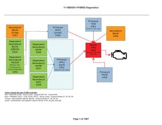
  • 1. Colors indicate the type of OBD controller. Red = MASTER (ECM) - Stores Codes - Supports M01-0A - Controls MIL Blue = PRIMARY (HPC1, TCM, FPCM, HPC2) - Stores Codes - Supports Modes 01, 04, 09, 0A Orange = SECONDARY (BECM, BSCM) - Supports Modes 01, 04, 09, 0A Green = DEPENDANT SECONDARY (MCPA, MCPB, ATPC, BCCM, EACCM) 11 OBDG01 HYBRID Diagnostics Page 1 of 1087
  • 2. System supply voltage is within limits > 11 Volts 20 failures out of 25 samples Trips 2 B Type Output driver is commanded on, Ignition switch is in crank or run position 250 ms /sample, continuous Secondary Parameters Enable Conditions Time Required MIL Illum Component / System Fault Code Monitor Strategy Description Malfunction Criteria Threshold Value Intake Camshaft Actuator Solenoid Circuit – Bank 1 P0010 Detects a VVT system error by monitoring the circuit for electrical integrity The ECM detects that the commanded state of the driver and the actual state of the control circuit do not match. 11 OBDG01 HYBRID Diagnostics ECM SECTION 1 OF 12 SECTIONS ECM SECTION Page 2 of 1087 1 OF 12 SECTIONS
  • 3. Secondary Parameters Enable Conditions Time Required MIL Illum Component / System Fault Code Monitor Strategy Description Malfunction Criteria Threshold Value Detects a VVT system error by comparing the desired and actual cam positions when VVT is activated Camshaft position error [absolute value of (desired position - actual position)] is compared to thresholds to determine if excessive (Intake cam Bank 1)Cam Position Error > KtPHSD_phi_C amPosErrorLim Ic1 Deg (see Supporting Table) DTC’s are NOT active: P0010 IntkCMP B1 Circuit IntakeCamSenso rTFTKO CrankSensorTFT KO CrankIntakeCam CorrelationFA System Voltage > 11 Volts, Both Desired & Measured cam positions cannot be < KtPHSD_phi_CamP osErrorLimIc1 or > than (29.0 - KtPHSD_phi_CamP osErrorLimIc1). Desired cam position cannot vary more than 3.0 Cam Deg for at least KtPHSD_t_StableP ositionTimeIc1 seconds (see Supporting Tables) 135 failures out of 150 samples Trips 2 B Type Intake Camshaft System Performance – Bank 1 P0011 11 OBDG01 HYBRID Diagnostics ECM SECTION 1 OF 12 SECTIONS ECM SECTION Page 3 of 1087 1 OF 12 SECTIONS
  • 4. Secondary Parameters Enable Conditions Time Required MIL Illum Component / System Fault Code Monitor Strategy Description Malfunction Criteria Threshold Value Engine is running VVT is enabled Desired camshaft position > 0 Power Take Off (PTO) not active 100 ms /sample Detects a VVT system error by monitoring the circuit for electrical integrity The ECM detects that the commanded state of the driver and the actual state of the control circuit do not match. System supply voltage is within limits > 11 Volts 20 failures out of 25 samples Trips 2 B Type Output driver is commanded on, Ignition switch is in crank or run position 250 ms /sample, continuous Exhaust Camshaft Actuator Solenoid Circuit – Bank 1 P0013 11 OBDG01 HYBRID Diagnostics ECM SECTION 1 OF 12 SECTIONS ECM SECTION Page 4 of 1087 1 OF 12 SECTIONS
  • 5. Secondary Parameters Enable Conditions Time Required MIL Illum Component / System Fault Code Monitor Strategy Description Malfunction Criteria Threshold Value Detects a VVT system error by comparing the desired and actual cam positions when VVT is activated Camshaft position error [absolute value of (desired position - actual position)] is compared to thresholds to determine if excessive (Exhaust cam Bank 1)Cam Position Error > KtPHSD_phi_C amPosErrorLim Ec1 Deg (see Supporting Table) DTC’s are NOT active: P0013 IntkCMP B1 Circuit ExhaustCamSen sorTFTKO CrankSensorTFT KO CrankExhaustCa mCorrelationFA System Voltage > 11 Volts, Both Desired & Measured cam positions cannot be < KtPHSD_phi_CamP osErrorLimEc1 or > than (Exh23.5 - KtPHSD_phi_CamP osErrorLimEc1). Desired cam position cannot vary more than 3.0 Cam Deg for at least KtPHSD_t_StableP ositionTimeEc1 seconds (see Supporting Tables) 135 failures out of 150 samples Trips 2 B Type Exhaust Camshaft System Performance – Bank 1 P0014 11 OBDG01 HYBRID Diagnostics ECM SECTION 1 OF 12 SECTIONS ECM SECTION Page 5 of 1087 1 OF 12 SECTIONS
  • 6. Secondary Parameters Enable Conditions Time Required MIL Illum Component / System Fault Code Monitor Strategy Description Malfunction Criteria Threshold Value Engine is running VVT is enabled Desired camshaft position > 0 Power Take Off (PTO) not active 100 ms /sample P0335, P0336 P0340, P0341 5VoltReferenceA_F A 5VoltReferenceB_F A Cam phaser is in "parked" position No Active DTCs: Crankshaft Position (CKP)- Camshaft Position (CMP) Correlation Bank 1 Sensor A P0016 Detects cam to crank misalignment by monitoring if cam sensor pulse for bank 1 sensor A occurs during the incorrect crank position 4 cam sensor pulses more than - 10 crank degrees before or 10 crank degrees after nominal position in one cam revolution. Crankshaft and camshaft position signals are synchronized 2 failures out of 3 tests. A failed test is 4 failures out of 5 samples. There is a delay after the first failed test to allow the camshaft position to return to the park position. This time is defined by the table "Cam Correlation Oil Temperature Threshold". Type B 2 trips Engine is Spinning 11 OBDG01 HYBRID Diagnostics ECM SECTION 1 OF 12 SECTIONS ECM SECTION Page 6 of 1087 1 OF 12 SECTIONS
  • 7. Secondary Parameters Enable Conditions Time Required MIL Illum Component / System Fault Code Monitor Strategy Description Malfunction Criteria Threshold Value P0335, P0336 Time since last execution of diagnostic < 1.0 seconds One sample per cam rotation Crankshaft Position (CKP)- Camshaft Position (CMP) Correlation Bank 1 Sensor B P0017 Detects cam to crank misalignment by monitoring if cam sensor pulse for bank 1 sensor B occurs during the incorrect crank position 4 cam sensor pulses more than - 10 crank degrees before or 10 crank degrees after nominal position in one cam revolution. Crankshaft and camshaft position signals are synchronized 2 failures out of 3 tests. A failed test is 4 failures out of 5 samples. There is a delay after the first failed test to allow the camshaft position to return to the park position. This time is defined by the Type B 2 trips Engine is Spinning Cam phaser is in "parked" position No Active DTCs: 11 OBDG01 HYBRID Diagnostics ECM SECTION 1 OF 12 SECTIONS ECM SECTION Page 7 of 1087 1 OF 12 SECTIONS
  • 8. Secondary Parameters Enable Conditions Time Required MIL Illum Component / System Fault Code Monitor Strategy Description Malfunction Criteria Threshold Value P0365, P0366 5VoltReferenceA_F A 5VoltReferenceB_F A Ignition = Crank or Run 20 failures out of 25 samples Ignition Voltage > 11.0 volts Engine Speed > 400 RPM 250 ms / sample Continuous O2S Heater Control Circuit Bank 1 Sensor 1 P0030 This DTC checks the Heater Output Driver circuit for electrical integrity. Voltage low during driver open state (indicates short-to- ground or open circuit) or voltage high during driver closed state (indicates short to voltage). 2 trips Type B y table "Cam Correlation Oil Temperature Threshold". Time since last execution of diagnostic < 1.0 seconds One sample per cam rotation 11 OBDG01 HYBRID Diagnostics ECM SECTION 1 OF 12 SECTIONS ECM SECTION Page 8 of 1087 1 OF 12 SECTIONS
  • 9. Secondary Parameters Enable Conditions Time Required MIL Illum Component / System Fault Code Monitor Strategy Description Malfunction Criteria Threshold Value Ignition = Crank or Run 20 failures out of 25 samples Ignition Voltage > 11.0 volts Engine Speed > 400 RPM 250 ms / sample Continuous Heater Resistance outside of the expected range of 7.0 < Ÿ < 13.0 No Active DTC's ECT_Sensor_FA P2610 IAT_SensorFA Once per valid cold start Coolant – IAT < 8.0 ºC Engine Soak Time > 28800 seconds Coolant Temp -30.0 < ºC < 45.0 Ignition Voltage < 32.0 volts Engine Run time < 0.275 seconds Heater Resistance outside of the expected range of 7.0 < Ÿ < 13.0 No Active DTC's ECT_Sensor_FA P2610 IAT_SensorFA Once per valid cold start Coolant – IAT < 8.0 ºC Engine Soak Time > 28800 seconds Coolant Temp -30.0 < ºC < 45.0 O2S Heater Control Circuit Bank 1 Sensor 2 P0036 This DTC checks the Heater Output Driver circuit for electrical integrity. Voltage low during driver open state (indicates short-to- ground or open circuit) or voltage high during driver closed state (indicates short to voltage). 2 trips Type B HO2S Heater Resistance Bank 1 Sensor 1 P0053 Detects an oxygen sensor heater having an incorrect or out of range resistance value. 2 trips Type B HO2S Heater Resistance Bank 1 Sensor 2 P0054 Detects an oxygen sensor heater having an incorrect or out of range resistance value. 2 trips Type B 11 OBDG01 HYBRID Diagnostics ECM SECTION 1 OF 12 SECTIONS ECM SECTION Page 9 of 1087 1 OF 12 SECTIONS
  • 10. Secondary Parameters Enable Conditions Time Required MIL Illum Component / System Fault Code Monitor Strategy Description Malfunction Criteria Threshold Value Ignition Voltage < 32.0 volts Engine Run time < 0.275 seconds Engine run time > 10.0 seconds Or IAT min ” 70.3 °C Continuous Engine run time > 60.0 seconds Or IAT min • -7.0 °C Continuous Radiator Coolant Temp Sensor Circuit Low Voltage P00B3 This DTC detects a short to ground in the RCT signal circuit or the RCT sensor. RCT Resistance (@ 150ºC) < 34 Ohms 5 failures out of 10 samples 2 trips Type B 1 sec/ sample Radiator Coolant Temp Sensor Circuit High Voltage P00B4 Circuit Continuity This DTC detects a short to high or open in the RCT signal circuit or the RCT sensor. RCT Resistance (@ -60ºC) > 260000 Ohms 5 failures out of 10 samples 2 trips Type B 1 sec/ sample 11 OBDG01 HYBRID Diagnostics ECM SECTION 1 OF 12 SECTIONS ECM SECTION Page 10 of 1087 1 OF 12 SECTIONS
  • 11. Secondary Parameters Enable Conditions Time Required MIL Illum Component / System Fault Code Monitor Strategy Description Malfunction Criteria Threshold Value No Active DTC's VehicleSpeedSenso r_FA 1 failure IAT_SensorCircuitF A THMR_RCT_Senso r_Ckt_FA THMR_ECT_Senso r_Ckt_FA IgnitionOffTimeVali d TimeSinceEngineR unningValid IAT • -7 ºC 2) Absolute difference between ECT at power up & RCT at power up is > by 20.0 C and a block heater has not b d t t d Test aborted this trip = False LowFuel Condition Diag = False Radiator Coolant Temp - Engine Coolant Temp (ECT) Correlation P00B6 This DTC detects a difference between ECT and RCT after a soak condition. A failure will be reported if any of the following occur: 2 trips Type B 500 msec/ sample 1) Absolute difference between ECT at power up & RCT at power up is • an IAT based threshold table lookup value(fast fail). See "P00B6: Fail if power up ECT exceeds RCT by these values" in the Supporting tables section Once per valid cold start Engine Off Soak Time > 28800 seconds Non-volatile memory initization = Not occurred Test complete this trip = False 11 OBDG01 HYBRID Diagnostics ECM SECTION 1 OF 12 SECTIONS ECM SECTION Page 11 of 1087 1 OF 12 SECTIONS
  • 12. Secondary Parameters Enable Conditions Time Required MIL Illum Component / System Fault Code Monitor Strategy Description Malfunction Criteria Threshold Value 2) Cranking time < 1.0 Seconds = False > 158.4 MPH and 1c) Additional Vehicle drive time is provided to 1a when Vehicle speed is below 1b as follows: 0.50 times the seconds with vehicle speed below 1b 1d) IAT drops from power up IAT • 255.0 ºC been detected. Block Heater detection is enabled 3) ECT at power up > IAT at power up by 20.0 C and the time spent cranking the engine without starting is greater than 1.0 seconds with the LowFuelConditionDi ag when either of the following 1) ECT at power up > IAT at power up by > 20.0 ºC Block Heater is detected and diagnostic is aborted when 1) or 2) occurs. Diagnostic is aborted when 3) or 4) occurs: 1a) Vehicle drive time > 1 Seconds with 1b) Vehicle speed 11 OBDG01 HYBRID Diagnostics ECM SECTION 1 OF 12 SECTIONS ECM SECTION Page 12 of 1087 1 OF 12 SECTIONS
  • 13. Secondary Parameters Enable Conditions Time Required MIL Illum Component / System Fault Code Monitor Strategy Description Malfunction Criteria Threshold Value > 255 Seconds No Active DTC's THMR_RCT_Senso r_Ckt_FA THMR_ECT_Senso r_Ckt_FA Engine run time > 45 seconds OR Continuous 2a) ECT drops from power up ECT > 255 ºC Within 2b) Engine run time 3) Engine run time with vehicle speed below 1b > 1800 Seconds 4) Minimum IAT during test ” -7.0 ºC Engine Coolant Flow Insufficient P00B7 This DTC detects a Insufficient Flow Condition (i.e.. Stuck Closed Thermostat) Engine Coolant Temp (ECT) is greater than 117 Deg C and Difference between ECT and RCT is greater than 45 Deg C. When above is present for more than 5 seconds, fail counts start. 30 failures out of 200 samples 2 trips Type B 1 sec/ sample Engine Coolant Temp > 70.0 Deg C 11 OBDG01 HYBRID Diagnostics ECM SECTION 1 OF 12 SECTIONS ECM SECTION Page 13 of 1087 1 OF 12 SECTIONS
  • 14. Secondary Parameters Enable Conditions Time Required MIL Illum Component / System Fault Code Monitor Strategy Description Malfunction Criteria Threshold Value Engine Speed >= 500 RPM Engine Speed <= 8000 RPM AND Coolant Temp >= -7 Deg C Coolant Temp <= 125 Deg C Intake Air Temp >= -20 Deg C Intake Air Temp <= 125 Deg C AND Mass Air Flow System Performance P0101 Determines if the MAF sensor is stuck within the normal operating range Filtered Throttle Model Error <= 125 kPa*(g/s) Continuous Calculation are performed every 12.5 msec Type B 2 trips ABS(Measured Flow – Modeled Air Flow) Filtered > 10 grams/sec Minimum total weight factor (all factors multiplied together) >= 0.25 ABS(Measured MAP – MAP Model 2) Filtered > 20.0 kPa Filtered Throttle Model Error multiplied by TPS Residual Weight Modeled Air Flow Error multiplied by MAF Residual Weight Factor based on RPM and MAF Residual MAP Model 2 Error multiplied by MAP2 11 OBDG01 HYBRID Diagnostics ECM SECTION 1 OF 12 SECTIONS ECM SECTION Page 14 of 1087 1 OF 12 SECTIONS
  • 15. Secondary Parameters Enable Conditions Time Required MIL Illum Component / System Fault Code Monitor Strategy Description Malfunction Criteria Threshold Value MAP_SensorCircuit FA EGRValve_FP EGRValvePerforma nce_FA MAF_SensorCircuit FA CrankSensor_FA ECT_Sensor_FA ECT_Sensor_Ckt_F P IAT_SensorFA IAT_SensorCircuitF P MAF Output <= 1800 Hertz Engine Run Time > 1.0 seconds (0 gm/sec) Engine Speed >= 300 RPM Ignition Voltage >= 10.0 Volts Mass Air Flow Sensor Circuit Low Frequency P0102 Detects a continuous short to low or a open in either the signal circuit or the MAF sensor 200 failures out of 250 samples Type B 2 trips Above criteria present for a period of time >= 1.0 seconds 1 sample every cylinder firing event Residual Weight Factor based on See table "IFRD Residual Weighting No Active DTCs: 11 OBDG01 HYBRID Diagnostics ECM SECTION 1 OF 12 SECTIONS ECM SECTION Page 15 of 1087 1 OF 12 SECTIONS
  • 16. Secondary Parameters Enable Conditions Time Required MIL Illum Component / System Fault Code Monitor Strategy Description Malfunction Criteria Threshold Value MAF Output >= 14500 Hertz Engine Run Time > 1.0 seconds (108 gm/sec) Engine Speed >= 300 RPM Ignition Voltage >= 10.0 Volts Engine Speed >= 500 RPM Engine Speed <= 8000 RPM AND Coolant Temp >= -7 Deg C Coolant Temp <= 125 Deg C Intake Air Temp >= -20 Deg C Intake Air Temp <= 125 Deg C AND Manifold Absolute Pressure Sensor Performance P0106 Determines if the MAP sensor is stuck within the normal operating range Filtered Throttle Model Error <= 125 kPa*(g/s) Continuous Calculations are performed every 12.5 msec Type B 2 trips ABS(Measured MAP – MAP Model 1) Filtered > 20.0 kPa Minimum total weight factor (all factors multiplied together) >= 0.25 ABS(Measured MAP – MAP Model 2) Filtered > 20.0 kPa Filtered Throttle Model Error multiplied by TPS Residual Weight MAP Model 1 Error multiplied by MAP1 Mass Air Flow Sensor Circuit High Frequency P0103 Detects a high frequency output from the MAF sensor 200 failures out of 250 samples Type B 2 trips Above criteria present for a period of time >= 1.0 seconds 1 sample every cylinder firing event 11 OBDG01 HYBRID Diagnostics ECM SECTION 1 OF 12 SECTIONS ECM SECTION Page 16 of 1087 1 OF 12 SECTIONS
  • 17. Secondary Parameters Enable Conditions Time Required MIL Illum Component / System Fault Code Monitor Strategy Description Malfunction Criteria Threshold Value MAP_SensorCircuit FA EGRValve_FP EGRValvePerforma nce_FA MAF_SensorCircuit FA CrankSensor_FA ECT_Sensor_FA ECT_Sensor_Ckt_F P IAT_SensorFA IAT_SensorCircuitF P Residual Weight Factor based on MAP Model 2 Error multiplied by MAP2 Residual Weight Factor based on See table "IFRD Residual Weighting No Active DTCs: Engine Not Rotating 11 OBDG01 HYBRID Diagnostics ECM SECTION 1 OF 12 SECTIONS ECM SECTION Page 17 of 1087 1 OF 12 SECTIONS
  • 18. Secondary Parameters Enable Conditions Time Required MIL Illum Component / System Fault Code Monitor Strategy Description Malfunction Criteria Threshold Value Manifold Pressure < 50.0 kPa OR Manifold Pressure > 115.0 kPa EngModeNotRunT mErr MAP_SensorFA AAP_SnsrFA MAP_SensorCircuit FP AAP_SnsrCktFP MAP Voltage Continuous MAP Voltage Continuous Manifold Absolute Pressure Sensor Circuit Low P0107 Detects a continuous short to low or open in either the signal circuit or the MAP sensor. < 3.0 % of 5 Volt Range (0.2 Volts = 3.5 kPa) 320 failures out of 400 samples Type B 2 trips 1 sample every 12.5 msec Manifold Absolute P0108 Detects an open sensor ground or > 90.0 % of 5 Volt Range (4.5 320 failures out of 400 samples Type B 2 trips Case: Time between current ignition cycle and the last time the engine was running > 8.0 seconds 4 failures out of 5 samples 1 sample every 12.5 msec Engine is not rotating No Active DTCs: No Pending DTCs: 11 OBDG01 HYBRID Diagnostics ECM SECTION 1 OF 12 SECTIONS ECM SECTION Page 18 of 1087 1 OF 12 SECTIONS
  • 19. Secondary Parameters Enable Conditions Time Required MIL Illum Component / System Fault Code Monitor Strategy Description Malfunction Criteria Threshold Value Power Up ECT < 60 deg C ECT_Sensor_Ckt_F A IAT_SensorCircuitF A MnfdTempSensorC ktFA HumTempSensorCkt Raw IAT Input Intake Air Temperature Sensor Circuit Low (High Temperature) P0112 Detects a continuous short to ground in the IAT signal circuit or the IAT sensor < 62 Ohms (~150 deg C) Engine Run Time > 0.0 seconds 40 failures out of 50 samples Type B 2 trips 1 sample every 100 msec Pressure Sensor Circuit High continuous short to high in either the signal circuit or the MAP sensor. Volts = 115.0 kPa) 1 sample every 12.5 msec Intake Air Temperature Sensor Circuit Performance P0111 Detects an IAT sensor that has stuck in range by comparing to engine coolant temperature at startup ABS(Power Up IAT - Power Up ECT) > 40 deg C Time between current ignition cycle and the last time the engine was running > 28800 seconds Executes once at the beginning of each ignition cycle if enable conditions are met Type B 2 trips No Active DTCs: 11 OBDG01 HYBRID Diagnostics ECM SECTION 1 OF 12 SECTIONS ECM SECTION Page 19 of 1087 1 OF 12 SECTIONS
  • 20. Secondary Parameters Enable Conditions Time Required MIL Illum Component / System Fault Code Monitor Strategy Description Malfunction Criteria Threshold Value Raw IAT Input String Length > 125 DegC Continuous Where: And where: No Active DTC's VehicleSpeedSensor1 failure IAT_SensorFA ECT_Sensor_Ckt_FA IgnitionOffTimeVali d TimeSinceEngineR unningValid Intake Air Temperature Sensor Intermittent In- Range P0114 Detects a noisy or erratic IAT signal circuit or IAT sensor 4 failures out of 5 samples Type B 2 trips 10 consecutive IAT samples "String Length" = sum of "Diff" calculated over "Diff" = ABS(current IAT reading - IAT reading from 100 milliseconds previous) Engine Coolant Temperature (ECT) Sensor Performance P0116 This DTC detects ECT temp sensor stuck in mid range. A failure will be reported if any of the following occur: 2 trips Type B 500 msec/ sample 1) ECT at power up > IAT at power up See "P0116: Fail if power up Intake Air Temperature Sensor Circuit High (Low Temperature) P0113 Detects a continuous open circuit in the IAT signal circuit or the IAT sensor > 126840 Ohms (~-60 deg C) Engine Run Time > 0.0 seconds 40 failures out of 50 samples Type B 2 trips 1 sample every 100 msec 11 OBDG01 HYBRID Diagnostics ECM SECTION 1 OF 12 SECTIONS ECM SECTION Page 20 of 1087 1 OF 12 SECTIONS
  • 21. Secondary Parameters Enable Conditions Time Required MIL Illum Component / System Fault Code Monitor Strategy Description Malfunction Criteria Threshold Value IAT • -7 ºC 2) Cranking time < 0.0 Seconds > 158.4 MPH = False Block Heater is detected and diagnostic is aborted when 1) or 2) occurs. Diagnostic is aborted when or 4) occurs: 1a) Vehicle drive time > 400 Seconds with 1b) Vehicle speed 1c) Additional by an IAT based table lookup value after a minimum 28800 second soak (fast fail). ECT exceeds IAT by these values" in the Supporting tables section Non-volatile memory = Not occurred Once per valid cold start Test complete this trip = False Test aborted this trip = False 2) ECT at power up > IAT at power up by 20.0 C after a minimum 28800 second soak and a block heater has not been detected. LowFuelConditio n = False Block Heater detection is enabled when either of the following 1) ECT at power up > IAT at power up by > 20.0 ºC 3) ECT at power up > IAT at power up by 20.0 C after a minimum 28800 seconds soak and the time spent cranking the engine without starting is greater than 0.0 seconds with the LowFuelConditionDi ag 11 OBDG01 HYBRID Diagnostics ECM SECTION 1 OF 12 SECTIONS ECM SECTION Page 21 of 1087 1 OF 12 SECTIONS
  • 22. Secondary Parameters Enable Conditions Time Required MIL Illum Component / System Fault Code Monitor Strategy Description Malfunction Criteria Threshold Value ” 65535 Seconds 4) Minimum IAT during test ” -7 ºC Engine Coolant Temp Sensor Circuit Low P0117 Circuit Continuity This DTC detects a short to ground in the ECT signal ECT Resistance (@ 150ºC) < 34 Ohms 5 failures out of 6 samples 2 trips Type B 1 sec/ sample Vehicle drive time is provided to 1a when Vehicle speed is below 1b as follows: 0.50 times the seconds with vehicle speed below 1b 1d) IAT drops from power up IAT • 255.0 ºC 2a) ECT drops from power up ECT • 255 ºC Within 2b) Engine run time 3) Engine run time with vehicle speed below 1b > 1800 Seconds 11 OBDG01 HYBRID Diagnostics ECM SECTION 1 OF 12 SECTIONS ECM SECTION Page 22 of 1087 1 OF 12 SECTIONS
  • 23. Secondary Parameters Enable Conditions Time Required MIL Illum Component / System Fault Code Monitor Strategy Description Malfunction Criteria Threshold Value Continuous Engine run time > 10.0 seconds Or IAT min • 0.0 °C Continuous No Active DTC's P0117 P0118 Continuous Engine Coolant Temperature (ECT) Sensor Circuit Intermittent P0119 Circuit Continuity This DTC detects large step changes in the ECT signal circuit or the ECT sensor. Allowable high and low limits are calculated for the next sample ECT temperature step change: 1) postive step change is greater than high limit OR 2) negitive step change is lower than low limit. 3 failures out of 4 samples 2 trips Type B 1 sec/ sample circuit or the ECT sensor. Engine Coolant Temp Sensor Circuit High P0118 Circuit Continuity This DTC detects a short to high or open in the ECT signal circuit or the ECT sensor. ECT Resistance (@ -60ºC) > 260000 Ohms 5 failures out of 6 samples 2 trips Type B 1 sec/ sample 11 OBDG01 HYBRID Diagnostics ECM SECTION 1 OF 12 SECTIONS ECM SECTION Page 23 of 1087 1 OF 12 SECTIONS
  • 24. Secondary Parameters Enable Conditions Time Required MIL Illum Component / System Fault Code Monitor Strategy Description Malfunction Criteria Threshold Value Engine Speed >= 500 RPM Engine Speed <= 8000 RPM AND Coolant Temp > -7 Deg C Coolant Temp < 125 Deg C Intake Air Temp > -20 Deg C Intake Air Temp < 125 Deg C AND p based on the previous sample and the time constant of the Throttle Position Sensor Performance P0121 Determines if the Throttle Position Sensor input is stuck within the normal operating range Filtered Throttle Model Error > 125 kPa*(g/s) Continuous Calculation are performed every 12.5 msec Type B 2 trips ABS(Measured Flow – Modeled Air Flow) Filtered > 10 grams/sec Minimum total weight factor (all factors multiplied together) >= 0.25 ABS(Measured MAP – MAP Model 2) Filtered <= 20.0 kPa Filtered Throttle Model Error multiplied by TPS Residual Weight Modeled Air Flow Error multiplied by MAF Residual Weight Factor based on RPM and MAF Residual 11 OBDG01 HYBRID Diagnostics ECM SECTION 1 OF 12 SECTIONS ECM SECTION Page 24 of 1087 1 OF 12 SECTIONS
  • 25. Secondary Parameters Enable Conditions Time Required MIL Illum Component / System Fault Code Monitor Strategy Description Malfunction Criteria Threshold Value MAP_SensorCircuit FA EGRValve_FP EGRValvePerforma nce_FA MAF_SensorCircuit FA CrankSensor_FA ECT_Sensor_FA ECT_Sensor_Ckt_F P IAT_SensorFA IAT_SensorCircuitF P TPS1 Voltage < 0.325 Trips: 1 Type: A MIL: YES TPS1 Circuit Low P0122 Detects a continuous or intermittent short or open in TPS1 circuit Run/Crank voltage > 6.41 639/1279 counts; 153 counts continuous; 3.125 ms /count in the ECM main processor No 5V reference error or fault for # 4 See table "IFRD Residual Weighting No Active DTCs: 11 OBDG01 HYBRID Diagnostics ECM SECTION 1 OF 12 SECTIONS ECM SECTION Page 25 of 1087 1 OF 12 SECTIONS
  • 26. Secondary Parameters Enable Conditions Time Required MIL Illum Component / System Fault Code Monitor Strategy Description Malfunction Criteria Threshold Value TPS1 Voltage > 4.75 Trips: 1 Type: A MIL: YES No Active DTC's MAF_SensorFA IAT_SensorFA THMR_RCT_Senso r_Ckt_FA THMR_ECT_Senso r_Ckt_FA Range #1 (Primary) 1 sec/ sample Engine not run time • 1800 seconds Fuel Condition Ethanol ” 86% 2 trips Type B ECT reaches Commanded temperature minus 11.0 °C when IAT min is < 60.0°C and • -7.0°C. Engine run time 1 ” Eng Run Tme ” 1800 seconds Once per ignition key cycle Range #1 (Primary) Test 5V reference circuit TPS1 Circuit High P0123 Detects a continuous or intermittent short or open in TPS1 circuit Run/Crank voltage > 6.41 639/1279 counts; 153 counts continuous; 3.125 ms /count in the ECM main processor No 5V reference error or fault for # 4 5V reference circuit Engine Coolant Temperature Below Stat Regulating Temperature P0128 This DTC detects if the engine coolant temperature rises too slowly due to an ECT or Cooling system fault Engine run time is accumulated when airflow is • 1 grams per sec during Range #1 or #2: See “P0128: Maximum Accumulated Time for IAT and Start-up ECT conditions“ in the Supporting 1 failure to set DTC 11 OBDG01 HYBRID Diagnostics ECM SECTION 1 OF 12 SECTIONS ECM SECTION Page 26 of 1087 1 OF 12 SECTIONS
  • 27. Secondary Parameters Enable Conditions Time Required MIL Illum Component / System Fault Code Monitor Strategy Description Malfunction Criteria Threshold Value ECT at start run -40.0 ” ECT ” 59.0 °C Average Airflow • 1.0 gps Not used in this application ECT at start run -50.0 ” ECT ” -50.0 °C Average Airflow • 1.0 gps No Active DTC's TPS_ThrottleAuthor ityDefaulted MAP_SensorFA AIR System FA Ethanol Composition Sensor FA EvapPurgeSolenoid Circuit_FA EvapFlowDuringNo nPurge_FA Range #2 (Alternate) ECT reaches Commanded temperature minus 11.0 °C when IAT min is < -50.0°C and • -50.0°C. T-Stat Heater duty commanded ” 10 % Range #2 (Alternate) Test T-Stat Heater duty commanded ” 10 % O2S Circuit Low Voltage Bank 1 Sensor 1 P0131 This DTC determines if the O2 sensor circuit is shorted to low. Oxygen Sensor Signal < 50 mVolts 380 failures out of 475 samples 2 trips Type B Frequency: Continuous in 100 milli - second loop 11 OBDG01 HYBRID Diagnostics ECM SECTION 1 OF 12 SECTIONS ECM SECTION Page 27 of 1087 1 OF 12 SECTIONS
  • 28. Secondary Parameters Enable Conditions Time Required MIL Illum Component / System Fault Code Monitor Strategy Description Malfunction Criteria Threshold Value EvapVentSolenoidC ircuit_FA EvapSmallLeak_FA EvapEmissionSyste m_FA FuelTankPressureS nsrCkt_FA FuelInjectorCircuit_ FA AIR intrusive test = Not active Fuel intrusive test = Not active Idle intrusive test = Not active EGR intrusive test = Not active System Voltage 10.0 < Volts < 32.0 EGR Device Control = Not active Idle Device Control = Not active Fuel Device Control = Not active AIR Device Control = Not active Low Fuel Condition Diag = False 11 OBDG01 HYBRID Diagnostics ECM SECTION 1 OF 12 SECTIONS ECM SECTION Page 28 of 1087 1 OF 12 SECTIONS
  • 29. Secondary Parameters Enable Conditions Time Required MIL Illum Component / System Fault Code Monitor Strategy Description Malfunction Criteria Threshold Value Equivalence Ratio 0.9912 < ratio < 1.0400 Air Per Cylinder 50 < mgram < 500 Fuel Control State = Closed Loop Closed Loop Active = TRUE All Fuel Injectors for active Cylinders Enabled (On) Fuel Condition Ethanol ” 87% Fuel State DFCO not active All of the above met for > 5.0 seconds 100 failures out of 125 samples No Active DTC's TPS_ThrottleAuthor ityDefaulted MAF_SensorFA EthanolComposition Sensor_FA System Voltage 10.0 < Volts < 32.0 AFM Status = All Cylinders active O2S Circuit High Voltage Bank 1 Sensor 1 P0132 This DTC determines if the O2 sensor circuit is shorted to high. Oxygen Sensor Signal > 1050 mvolts Open Test Criteria 2 trips Type B Frequency: Continuous in 100 milli - second loop 11 OBDG01 HYBRID Diagnostics ECM SECTION 1 OF 12 SECTIONS ECM SECTION Page 29 of 1087 1 OF 12 SECTIONS
  • 30. Secondary Parameters Enable Conditions Time Required MIL Illum Component / System Fault Code Monitor Strategy Description Malfunction Criteria Threshold Value Heater Warm-up delay = Complete Engine Run Time > 5 seconds Engine Run Accum > 150 seconds Fuel Condition ” 87 % Ethanol No Active DTC's MAP_SensorFA EvapPurgeSolenoid Circuit_FA EvapFlowDuringNo nPurge_FA EvapVentSolenoidC ircuit_FA EvapSmallLeak_FA EvapEmissionSyste m_FA FuelTankPressureS nsrCkt_FA FuelInjectorCircuit_ FA AIR System FA Low Fuel Condition Diag = False Fuel Condition ” 87 % Ethanol 11 OBDG01 HYBRID Diagnostics ECM SECTION 1 OF 12 SECTIONS ECM SECTION Page 30 of 1087 1 OF 12 SECTIONS
  • 31. Secondary Parameters Enable Conditions Time Required MIL Illum Component / System Fault Code Monitor Strategy Description Malfunction Criteria Threshold Value Initial delay after Open Test Criteria met (cold start condition) > 45.0 seconds when engine soak time > 28800 seconds Initial delay after Open Test Criteria met (not cold start condition) > 45.0 seconds when engine soak time ” 28800 seconds Equivalence Ratio 0.9912 ” ratio ” 1.0400 Air Per Cylinder 50.0 ” mgram ” 500.0 Fuel Control State not = Power Enrichment All of the above met for > 5.0 seconds No Active DTC's TPS_ThrottleAuthor ityDefaulted Sample time is 60 seconds MAP_SensorFA IAT_SensorFA ECT_Sensor_FA Frequency: AmbientAirDefault Once per trip MAF_SensorFA O2S Slow Response Bank 1 Sensor 1 P0133 This DTC determines if the O2 sensor response time is degraded. The average response time is caluclated over the test time, and compared to the threshold. Refer to “P0133 - O2S Slow 2 trips Type B 11 OBDG01 HYBRID Diagnostics ECM SECTION 1 OF 12 SECTIONS ECM SECTION Page 31 of 1087 1 OF 12 SECTIONS
  • 32. Secondary Parameters Enable Conditions Time Required MIL Illum Component / System Fault Code Monitor Strategy Description Malfunction Criteria Threshold Value EvapPurgeSolenoid Circuit_FA EvapFlowDuringNo nPurge_FA EvapVentSolenoidC ircuit_FA EvapSmallLeak_FA EvapEmissionSyste m_FA FuelTankPressureS nsrCkt_FA FuelInjectorCircuit_ FA AIR System FA EthanolComposition Sensor_FA EngineMisfireDetect ed_FA P0131 P0132 P0134 System Voltage 10.0 < Volts < 32.0 EGR Device Control = Not active Idle Device Control = Not active Response Bank 1 Sensor 1" Pass/Fail Threshold table in the Supporting Tables tab. 11 OBDG01 HYBRID Diagnostics ECM SECTION 1 OF 12 SECTIONS ECM SECTION Page 32 of 1087 1 OF 12 SECTIONS
  • 33. Secondary Parameters Enable Conditions Time Required MIL Illum Component / System Fault Code Monitor Strategy Description Malfunction Criteria Threshold Value Fuel Device Control = Not active AIR Device Control = Not active Low Fuel Condition Diag = False Green O2S Condition = Not Valid, See definition of Green Sensor Delay Criteria (B1S1) in Supporting Tables tab. O2 Heater on for • 40 seconds Learned Htr resistance = Valid Engine Coolant > 50 ºC IAT > -40 ºC Engine run Accum > 90 seconds Time since any AFM status change > 2.0 seconds Time since Purge On to Off change > 2.0 seconds 11 OBDG01 HYBRID Diagnostics ECM SECTION 1 OF 12 SECTIONS ECM SECTION Page 33 of 1087 1 OF 12 SECTIONS
  • 34. Secondary Parameters Enable Conditions Time Required MIL Illum Component / System Fault Code Monitor Strategy Description Malfunction Criteria Threshold Value Time since Purge Off to On change > 2.0 seconds Engine airflow 17 ” grams per second ” 40 Engine speed 1000 <= RPM <= 3500 Fuel < 87 % Ethanol Baro > 70 kpa Air Per Cylinder • 150 mGrams Low Fuel Condition Diag = False Fuel Control State = Closed Loop Closed Loop Active = TRUE LTM fuel cell = Enabled Transient Fuel Mass ” 100.0 mgrams Baro = Not Defaulted Fuel Control State not = Power Enrichment Fuel State DFCO not active Commanded Proportional Gain • 0.0 % 11 OBDG01 HYBRID Diagnostics ECM SECTION 1 OF 12 SECTIONS ECM SECTION Page 34 of 1087 1 OF 12 SECTIONS
  • 35. Secondary Parameters Enable Conditions Time Required MIL Illum Component / System Fault Code Monitor Strategy Description Malfunction Criteria Threshold Value All of the above met for > 1.0 seconds No Active DTC's TPS_ThrottleAuthor ityDefaulted 200 failures out of 250 samples. MAF_SensorFA EthanolComposition Sensor_FA Frequency: Continuous System Voltage 10.0 < Volts < 32.0 AFM Status = All Cylinders active 100msec loop Heater Warm-up delay = Complete Engine Run Time > 5 seconds Engine Run Accum > 150 seconds Fuel ” 87 % Ethanol No Active DTC's ECT_Sensor_FA 8 failures out of 10 samples System Voltage 10.0 < Volts < 32.0 Heater Warm-up delay = Complete Frequency: 2 tests per trip O2S Heater device control = Not active O2S Heater Performance Bank 1 Sensor 1 P0135 This DTC determines if the O2 sensor heater is functioning properly by monitoring the Heater Current outside of the expected range of 0.3 < Amps < 2.5 2 trips Type B O2S Circuit Insufficient Activity Bank 1 Sensor 1 P0134 This DTC determines if the O2 sensor circuit is open. Oxygen Sensor Signal > 1700 mvolts 2 trips Type B 11 OBDG01 HYBRID Diagnostics ECM SECTION 1 OF 12 SECTIONS ECM SECTION Page 35 of 1087 1 OF 12 SECTIONS
  • 36. Secondary Parameters Enable Conditions Time Required MIL Illum Component / System Fault Code Monitor Strategy Description Malfunction Criteria Threshold Value B1S1 O2S Heater Duty Cycle > zero 30 seconds delay between tests and 1 second execution rate All of the above met for > 120 seconds No Active DTC's TPS_ThrottleAuthor ityDefaulted MAP_SensorFA AIR System FA Ethanol Composition Sensor FA EvapPurgeSolenoid Circuit_FA EvapFlowDuringNo nPurge_FA EvapVentSolenoidC ircuit_FA EvapSmallLeak_FA EvapEmissionSyste m_FA FuelTankPressureS nsrCkt_FA current through the heater circuit. O2S Circuit Low Voltage Bank 1 Sensor 2 P0137 This DTC determines if the O2 sensor circuit is shorted to low. Oxygen Sensor Signal < 50 mvolts 430 failures out of 540 samples 2 trips Type B Frequency: Continuous in 100 milli - second loop 11 OBDG01 HYBRID Diagnostics ECM SECTION 1 OF 12 SECTIONS ECM SECTION Page 36 of 1087 1 OF 12 SECTIONS
  • 37. Secondary Parameters Enable Conditions Time Required MIL Illum Component / System Fault Code Monitor Strategy Description Malfunction Criteria Threshold Value FuelInjectorCircuit_ FA AIR intrusive test = Not active Fuel intrusive test = Not active Idle intrusive test = Not active EGR intrusive test = Not active System Voltage 10.0 < Volts < 32.0 EGR Device Control = Not active Idle Device Control = Not active Fuel Device Control = Not active AIR Device Control = Not active Low Fuel Condition Diag = False Equivalence Ratio 0.9912 ” ratio ” 1.0400 Air Per Cylinder 50 ” mgrams ” 500 Fuel Control State = Closed Loop Closed Loop Active = TRUE 11 OBDG01 HYBRID Diagnostics ECM SECTION 1 OF 12 SECTIONS ECM SECTION Page 37 of 1087 1 OF 12 SECTIONS
  • 38. Secondary Parameters Enable Conditions Time Required MIL Illum Component / System Fault Code Monitor Strategy Description Malfunction Criteria Threshold Value All Fuel Injectors for active Cylinders Enabled (On) Fuel Condition Ethanol <= 87% Fuel State DFCO not active All of the above met for > 5.0 seconds No Active DTC's TPS_ThrottleAuthor ityDefaulted MAF_SensorFA EthanolComposition Sensor_FA System Voltage 10.0 < Volts < 32.0 AFM Status = All Cylinders active Heater Warm-up delay = Complete Engine Run Time > 5 seconds Fuel Condition ” 87 % Ethanol No Active DTC's MAP_SensorFA EvapPurgeSolenoid Circuit_FA O2S Circuit High Voltage Bank 1 Sensor 2 P0138 This DTC determines if the O2 sensor circuit is shorted to high. Oxygen Sensor Signal > 1050 mvolts Open Test Criteria 100 failures out of 125 samples 2 trips Type B Frequency: Continuous in 100 milli - second loop 11 OBDG01 HYBRID Diagnostics ECM SECTION 1 OF 12 SECTIONS ECM SECTION Page 38 of 1087 1 OF 12 SECTIONS
  • 39. Secondary Parameters Enable Conditions Time Required MIL Illum Component / System Fault Code Monitor Strategy Description Malfunction Criteria Threshold Value EvapFlowDuringNo nPurge_FA EvapVentSolenoidC ircuit_FA EvapSmallLeak_FA EvapEmissionSyste m_FA FuelTankPressureS nsrCkt_FA FuelInjectorCircuit_ FA AIR System FA Low Fuel Condition Diag = False Fuel Condition ” 87 % Ethanol Initial delay after Open Test Criteria met (cold start condition) > 45.0 seconds when engine soak time > 28800 seconds Initial delay after Open Test Criteria met (not cold start condition) > 45.0 seconds when engine soak time ” 28800 seconds 11 OBDG01 HYBRID Diagnostics ECM SECTION 1 OF 12 SECTIONS ECM SECTION Page 39 of 1087 1 OF 12 SECTIONS
  • 40. Secondary Parameters Enable Conditions Time Required MIL Illum Component / System Fault Code Monitor Strategy Description Malfunction Criteria Threshold Value Equivalence Ratio 0.9912 ” ratio ” 1.0400 Air Per Cylinder 50 ” mgrams ” 500 Fuel Control State not = Power Enrichment All of the above met for > 5.0 seconds No Active DTC's TPS_ThrottleAuthor ityDefaulted ECT_Sensor_FA IAT_SensorFA MAF_SensorFA MAP_SensorFA AIR System FA FuelInjectorCircuit_ FA FuelTrimSystemB1 _FA FuelTrimSystemB2 _FA EngineMisfireDetect ed_FA EthanolComposition Sensor_FA O2 Sensor Slow Response Rich to Lean Bank 1 Sensor 2 P013A This DTC determines if the post catalyst O2 sensor has Slow Response in a predefined Rich to Lean voltages range during Rich to Lean transition. The diagnostic is an intrusive test which runs in a DFCO mode to achieve the required response. The EWMA of the Post O2 sensor normalized integral value OR The Accumulated mass air flow monitored during the Slow Response Test (between the upper and lower voltage thresholds) > 8.0 units > 74 grams (upper threshold is 450 mvolts and lower threshold Frequency: Once per trip Note: if NaPOPD_b_Re setFastRespFun c= FALSE for the given Fuel Bank OR NaPOPD_b_Ra pidResponseAct ive = TRUE, multiple tests per trip are allowed. 1 trips Type A EWMA B1S2 Failed this P013B, P013E, 11 OBDG01 HYBRID Diagnostics ECM SECTION 1 OF 12 SECTIONS ECM SECTION Page 40 of 1087 1 OF 12 SECTIONS
  • 41. Secondary Parameters Enable Conditions Time Required MIL Illum Component / System Fault Code Monitor Strategy Description Malfunction Criteria Threshold Value System Voltage 10.0 < Volts < 32.0 Green O2S Condition = Not Valid, See definition of Green Sensor Delay Criteria (B1S2) in Supporting Tables tab. Post fuel cell = enabled lower threshold is 150 mvolts) key cycle , , P013F, P2270 or P2271 Learned heater resistance = Valid ICAT MAT Burnoff delay = Not Valid Low Fuel Condition Diag = False DTC's Passed P2270 (and P2272 if applicable) DTC's Passed P013E (and P014A if applicable) After above conditions are met: DFCO mode is continued (wo driver initiated pedal input). 11 OBDG01 HYBRID Diagnostics ECM SECTION 1 OF 12 SECTIONS ECM SECTION Page 41 of 1087 1 OF 12 SECTIONS
  • 42. Secondary Parameters Enable Conditions Time Required MIL Illum Component / System Fault Code Monitor Strategy Description Malfunction Criteria Threshold Value No Active DTC's TPS_ThrottleAuthor ityDefaulted ECT_Sensor_FA IAT_SensorFA MAF_SensorFA MAP_SensorFA AIR System FA FuelInjectorCircuit_ FA FuelTrimSystemB1 _FA FuelTrimSystemB2 _FA EngineMisfireDetect ed_FA EthanolComposition Sensor_FA System Voltage 10.0 < Volts < 32.0 O2 Sensor Slow Response Lean to Rich Bank 1 Sensor 2 P013B This DTC determines if the post catalyst O2 sensor has Slow Response in a predefined Lean to Rich voltages range during Lean to Rich transition. The diagnostic is an intrusive test which increases the delivered A/F ratio to achieve the required rich threshold. The EWMA of the Post O2 sensor normalized integral value OR The Accumulated mass air flow monitored during the Slow Response Test (between the upper and lower voltage thresholds) > 8.0 units > 120 grams (lower threshold is 350 mvolts and upper threshold is 600 mvolts) Frequency: Once per trip Note: if NaPOPD_b_Re setFastRespFun c= FALSE for the given Fuel Bank OR NaPOPD_b_Ra pidResponseAct ive = TRUE, multiple tests per trip are allowed. 1 trips Type A EWMA B1S2 Failed this key cycle P013A, P013E, P013F, P2270 or P2271 Learned heater resistance = Valid ICAT MAT Burnoff delay = Not Valid 11 OBDG01 HYBRID Diagnostics ECM SECTION 1 OF 12 SECTIONS ECM SECTION Page 42 of 1087 1 OF 12 SECTIONS
  • 43. Secondary Parameters Enable Conditions Time Required MIL Illum Component / System Fault Code Monitor Strategy Description Malfunction Criteria Threshold Value Green O2S Condition = Not Valid, See definition of Green Sensor Delay Criteria (B1S2) in Supporting Tables tab. Post fuel cell = enabled Low Fuel Condition Diag = False DTC's Passed P2270 (and P2272 if applicable) P013E (and P014A if applicable) P013A (and P013C if applicable) P2271 (and P2273 if applicable) P013F (and P014B if applicable) After above conditions are met: Fuel Enrich mode continued. 11 OBDG01 HYBRID Diagnostics ECM SECTION 1 OF 12 SECTIONS ECM SECTION Page 43 of 1087 1 OF 12 SECTIONS
  • 44. Secondary Parameters Enable Conditions Time Required MIL Illum Component / System Fault Code Monitor Strategy Description Malfunction Criteria Threshold Value No Active DTC's TPS_ThrottleAuthor ityDefaulted ECT_Sensor_FA IAT_SensorFA MAF_SensorFA MAP_SensorFA AIR System FA FuelInjectorCircuit_ FA FuelTrimSystemB1 _FA FuelTrimSystemB2 _FA EngineMisfireDetect ed_FA EthanolComposition Sensor_FA System Voltage 10.0 < Volts < 32.0 O2 Sensor Delayed Response Rich to Lean Bank 1 Sensor 2 P013E This DTC determines if the post catalyst O2 sensor has an initial delayed response to an A/F change from Rich to Lean. The diagnostic is an intrusive test which runs in a DFCO mode to achieve the required response. Post O2 sensor voltage AND The Accumulated mass air flow monitored during the Delayed Response Test under DFCO DFCO begins after: 1) Catalyst has been rich for a minimum of AND 2) Catalyst Rich Accumulation Air Flow is greater or equal to > 450 mvolts > 33 grams > 2 secs > 2 grams Frequency: Once per trip Note: if NaPOPD_b_Re setFastRespFun c= FALSE for the given Fuel Bank OR NaPOPD_b_Ra pidResponseAct ive = TRUE, multiple tests per trip are allowed. 2 trips Type B B1S2 Failed this key cycle P013A, P013B, P013F, P2270 or P2271 Learned heater resistance = Valid ICAT MAT Burnoff delay = Not Valid 11 OBDG01 HYBRID Diagnostics ECM SECTION 1 OF 12 SECTIONS ECM SECTION Page 44 of 1087 1 OF 12 SECTIONS
  • 45. Secondary Parameters Enable Conditions Time Required MIL Illum Component / System Fault Code Monitor Strategy Description Malfunction Criteria Threshold Value Green O2S Condition = Not Valid, See definition of Green Sensor Delay Criteria (B1S2) in Supporting Tables tab. Post fuel cell = enabled No Active DTC's TPS_ThrottleAuthor ityDefaulted ECT_Sensor_FA IAT_SensorFA MAF_SensorFA MAP_SensorFA AIR System FA FuelInjectorCircuit_ FA FuelTrimSystemB1 _FA O2 Sensor Delayed Response Lean to Rich Bank 1 Sensor 2 P013F This DTC determines if the post catalyst O2 sensor has an initial delayed response to an A/F change from Lean to Rich. The diagnostic is an intrusive test which increases Post O2 sensor voltage AND The Accumulated mass air flow monitored during the Delayed Response Test < 350 mvolts > 120 grams Frequency: Once per trip Note: if NaPOPD_b_Re setFastRespFun c= FALSE for the given Fuel Bank OR NaPOPD_b_Ra pidResponseAct ive = TRUE, 2 trips Type B Low Fuel Condition Diag = False DTC's Passed P2270 (and P2272 if applicable) After above conditions are met: DFCO mode entered (wo driver 11 OBDG01 HYBRID Diagnostics ECM SECTION 1 OF 12 SECTIONS ECM SECTION Page 45 of 1087 1 OF 12 SECTIONS
  • 46. Secondary Parameters Enable Conditions Time Required MIL Illum Component / System Fault Code Monitor Strategy Description Malfunction Criteria Threshold Value FuelTrimSystemB2 _FA EngineMisfireDetect ed_FA EthanolComposition Sensor_FA System Voltage 10.0 < Volts < 32.0 Green O2S Condition = Not Valid, See definition of Green Sensor Delay Criteria (B1S2) in Supporting Tables tab. Post fuel cell = enabled the delivered A/F ratio to achieve the required rich threshold. multiple tests per trip are allowed B1S2 Failed this key cycle P013A, P013B, P013E, P2270 or P2271 Learned heater resistance = Valid ICAT MAT Burnoff delay = Not Valid Low Fuel Condition Diag = False DTC's Passed P2270 (and P2272 if applicable) 11 OBDG01 HYBRID Diagnostics ECM SECTION 1 OF 12 SECTIONS ECM SECTION Page 46 of 1087 1 OF 12 SECTIONS
  • 47. Secondary Parameters Enable Conditions Time Required MIL Illum Component / System Fault Code Monitor Strategy Description Malfunction Criteria Threshold Value No Active DTC's TPS_ThrottleAuthor ityDefaulted MAF_SensorFA EthanolComposition Sensor_FA System Voltage 10.0 <Volts < 32.0 AFM Status = All Cylinders active 100msec loop Engine Run Time > 5 seconds Engine Run Accum > 150 seconds Fuel ” 87 % Ethanol O2S Circuit Insufficient Activity Bank 1 Sensor 2 P0140 This DTC determines if the O2 sensor circuit is open. Oxygen Sensor Signal > 1700 mvolts 200 failures out of 250 samples. 2 trips Type B Frequency: Continuous Heater Warm-up delay = Complete P013E (and P014A if applicable) P013A (and P013C if applicable) P2271 (and P2273 if applicable) After above conditions are met: Fuel Enrich mode entered. 11 OBDG01 HYBRID Diagnostics ECM SECTION 1 OF 12 SECTIONS ECM SECTION Page 47 of 1087 1 OF 12 SECTIONS
  • 48. Secondary Parameters Enable Conditions Time Required MIL Illum Component / System Fault Code Monitor Strategy Description Malfunction Criteria Threshold Value No Active DTC's ECT_Sensor_FA System Voltage 10.0 < Volts < 32.0 Time > 120 seconds Engine speed 400 <rpm< 6100 BARO > 70 kPa Coolant Temp -38 <°C< 130 MAP 15 <kPa< 255 Inlet Air Temp -20 <°C< 150 MAF 1.0 <g/s< 512.0 Fuel Level Fuel System Too Lean Bank 1 P0171 Determines if the fuel control system is in a lean condition, based on the filtered long-term fuel trim. The filtered long- term fuel trim metric >= 1.250 Frequency: 100 ms Continuous Loop 2 Trip(s) Type B > 10 % or if fuel sender is faulty Long Term Fuel Trim data accumulation: > 20.0 seconds of data must accumulate on each trip, with at least O2S Heater Performance Bank 1 Sensor 2 P0141 This DTC determines if the O2 sensor heater is functioning properly by monitoring the current through the heater circuit. Heater Current outside of the expected range of 0.3 > amps > 2.5 8 failures out of 10 samples 2 trips Type B Heater Warm-up delay = Complete Frequency: 2 tests per trip O2S Heater device control = Not active 30 seconds delay between tests and 1 second execution rate. B1S1 O2S Heater Duty C l > zero All of the above met for 11 OBDG01 HYBRID Diagnostics ECM SECTION 1 OF 12 SECTIONS ECM SECTION Page 48 of 1087 1 OF 12 SECTIONS
  • 49. Secondary Parameters Enable Conditions Time Required MIL Illum Component / System Fault Code Monitor Strategy Description Malfunction Criteria Threshold Value Closed Loop Enabled Long Term FT Enabled 15.0 seconds of data in the current fuel trim cell before fuel trim diagnosed during decels? No Long-Term Fuel Trim Cell Usage Sometimes, certain Long-Term Fuel Cells are not utilized for control or diagnosis. Please see "Supporting Tables" Tab for a list of cells for diagnosis. Fuel Control Status Please see "Closed Loop Enable Criteria" and "Long Term FT Enable Criteria" in Supporting Tables. 11 OBDG01 HYBRID Diagnostics ECM SECTION 1 OF 12 SECTIONS ECM SECTION Page 49 of 1087 1 OF 12 SECTIONS
  • 50. Secondary Parameters Enable Conditions Time Required MIL Illum Component / System Fault Code Monitor Strategy Description Malfunction Criteria Threshold Value Fuel Consumed > 65535.0 liters of fuel consumed after a fuel fill event ("Virtual Flex Fuel Sensor applications only) AIR System FA EvapExcessPurgePsbl_FA Ethanol Composition Sensor FA FuelInjectorCircuit_FA EngineMisfireDetected_FA EGRValvePerformance_FA EGRValveCircuit_FA MAP_EngineVacuumStatus AmbPresDfltdStatus EVAP Diag. “tank pull down” Not Active No active DTCs: IAC_SystemRPM_FA MAP_SensorFA MAF_SensorFA MAF_SensorTFTKO EGR Flow Diag. Intrusive Test Not Catalyst Monitor Intrusive Test Not Post O2 Diag. Intrusive Test Not Device Control Not Active 11 OBDG01 HYBRID Diagnostics ECM SECTION 1 OF 12 SECTIONS ECM SECTION Page 50 of 1087 1 OF 12 SECTIONS
  • 51. Secondary Parameters Enable Conditions Time Required MIL Illum Component / System Fault Code Monitor Strategy Description Malfunction Criteria Threshold Value <= 0.795 <= 0.800 <= 0.795 for Frequency: 100 ms Continuous Loop 2 Trip(s) Type B The filtered Non- Purge Long Term Fuel Trim metric (a Passive Test decision cannot be made when Purge is enabled) Intrusive Test: The filtered Purge Long Term Fuel Trim metric AND The filtered Non- Purge Long Term Fuel Trim metric 2 out of 3 intrusive TC_BoostPresSnsrFA O2S_Bank_1_Sensor_1_FA Fuel System Too Rich Bank 1 P0172 Determines if the fuel control system is in a rich condition, based on the filtered long-term fuel trim metric. There are two methods to determine a Rich fault. They are Passive and Intrusive. The Intrusive test is described below: Passive Test: Secondary Parameters and Enable Conditions are identical to those for P0171, with the exception 11 OBDG01 HYBRID Diagnostics ECM SECTION 1 OF 12 SECTIONS ECM SECTION Page 51 of 1087 1 OF 12 SECTIONS
  • 52. Secondary Parameters Enable Conditions Time Required MIL Illum Component / System Fault Code Monitor Strategy Description Malfunction Criteria Threshold Value segments Intrusive Test: When the filtered Purge Long Term Fuel Trim metric is <= 0.800, purge is ramped off to determine if excess purge vapor is the cause of the rich condition. If the filtered Purge Long Term Fuel Trim metric > 0.800, the test passes without checking the filtered Non- Purge Long Term Fuel Trim metric. Segment Def'n: Segments can last up to 35 seconds and are separated by the lesser of 30 seconds of purge- on time or enough time to purge 5 grams of vapor. A maximum of 3 completed segments or 25 attempts are allowed for each intrusive test. After an intrusive test report is completed, another intrusive test cannot occur for 299 seconds to allow 11 OBDG01 HYBRID Diagnostics ECM SECTION 1 OF 12 SECTIONS ECM SECTION Page 52 of 1087 1 OF 12 SECTIONS
  • 53. Secondary Parameters Enable Conditions Time Required MIL Illum Component / System Fault Code Monitor Strategy Description Malfunction Criteria Threshold Value Injector 1 P0201 This DTC checks the circuit for electrical integrity during operation. The ECM detects that the commanded state of the driver and the actual state of the control ciruit do not match Powertrain Relay Voltage within range and stable according to Enable Conditions Engine Running 11 volts ” Voltage for greater than 5 seconds 20 failures out of 25 samples 250 ms /sample Continuous 2 trips Type B Performing intrusive tests too frequently may also affect EVAP and EPAIII emissions, and the execution frequency of other diagnostics. sufficient time to purge excess vapors from the canister. During this period, fuel trim will pass if the filtered Purge-on Long Term fuel trim > Purge Rich Limit Table for at least 150 seconds, indicating that the canister has been purged. 11 OBDG01 HYBRID Diagnostics ECM SECTION 1 OF 12 SECTIONS ECM SECTION Page 53 of 1087 1 OF 12 SECTIONS
  • 54. Secondary Parameters Enable Conditions Time Required MIL Illum Component / System Fault Code Monitor Strategy Description Malfunction Criteria Threshold Value Injector 2 P0202 This DTC checks the circuit for electrical integrity during operation. The ECM detects that the commanded state of the driver and the actual state of the control ciruit do not match Powertrain Relay Voltage within range and stable according to Enable Conditions Engine Running 11 volts ” Voltage for greater than 5 seconds 20 failures out of 25 samples 250 ms /sample Continuous 2 trips Type B Injector 3 P0203 This DTC checks the circuit for electrical integrity during operation. The ECM detects that the commanded state of the driver and the actual state of the control ciruit do not match Powertrain Relay Voltage within range and stable according to Enable Conditions Engine Running 11 volts ” Voltage for greater than 5 seconds 20 failures out of 25 samples 250 ms /sample Continuous 2 trips Type B Injector 4 P0204 This DTC checks the circuit for electrical integrity during operation. The ECM detects that the commanded state of the driver and the actual state of the control ciruit do not match Powertrain Relay Voltage within range and stable according to Enable Conditions Engine Running 11 volts ” Voltage for greater than 5 seconds 20 failures out of 25 samples 250 ms /sample Continuous 2 trips Type B TPS2 Voltage < 0.25 Trips: 1 Type: TPS2 Circuit Low P0222 Detects a continuous or intermittent short Run/Crank voltage > 6.41 639/1279 counts; 153 counts 11 OBDG01 HYBRID Diagnostics ECM SECTION 1 OF 12 SECTIONS ECM SECTION Page 54 of 1087 1 OF 12 SECTIONS
  • 55. Secondary Parameters Enable Conditions Time Required MIL Illum Component / System Fault Code Monitor Strategy Description Malfunction Criteria Threshold Value A MIL: YES TPS2 Voltage > 4.59 Trips: 1 Type: A MIL: YES Engine Run Time > 2 crankshaft revolutions 2 Trips ECT -7ºC < ECT < 125ºC Type B TPS2 Circuit High P0223 Detects a continuous or intermittent short or open in TPS2 circuit Run/Crank voltage > 6.41 639/1279 counts; 153 counts continuous; 3.125 ms /count in the ECM main processor No 5V reference error or fault for # 4 5V reference circuit Random Misfire Detected P0300 P0301 These DTC’s will determine if a random or a cylinder specific Deceleration index vs. Engine Speed Vs Engine load (>Idle SCD AND > Idle SCD ddt Tables) Emission Exceedence = any (5) failed 200 rev blocks or open in TPS2 circuit continuous; 3.125 ms /count in the ECM main processor No 5V reference error or fault for # 4 5V reference circuit 11 OBDG01 HYBRID Diagnostics ECM SECTION 1 OF 12 SECTIONS ECM SECTION Page 55 of 1087 1 OF 12 SECTIONS
  • 56. Secondary Parameters Enable Conditions Time Required MIL Illum Component / System Fault Code Monitor Strategy Description Malfunction Criteria Threshold Value If ECT at startup < -7ºC (Mil Flashes with Catalyst Damagi ng Misfire) then ECT 21ºC < ECT < 125ºC System Voltage 9.00 < volts < 32.00 + Throttle delta < 100.00% per 25 ms - Throttle delta < 100.00% per 25 ms Cylinder 1 Misfire Detected Cylinder 2 Misfire Detected Cylinder 3 Misfire Detected Cylinder 4 Misfire Detected P0302 P0303 P0304 P0305 P0306 misfire is occurring by monitoring crankshaft velocity Deceleration index calculation is tailored to specific veh. Tables used are 1st tables encountered that are not max of range. Undetectable region at a given speed/load point is where all tables are max of range point. see Algorithm Description OR (>SCD Delta AND > SCD Delta ddt Tables) OR (>Idle Cyl Mode AND > Idle Cyl Mode ddt Tables) OR (>Cyl Mode AND > Cyl Mode ddt Tables) OR out of (16) 200 rev block tests Failure reported for (1) Exceedence in 1st (16) 200 rev block tests, or (4) Exceedences thereafter. 11 OBDG01 HYBRID Diagnostics ECM SECTION 1 OF 12 SECTIONS ECM SECTION Page 56 of 1087 1 OF 12 SECTIONS
  • 57. Secondary Parameters Enable Conditions Time Required MIL Illum Component / System Fault Code Monitor Strategy Description Malfunction Criteria Threshold Value Early Termination option NotEnabled OR when Early Termination Reporting = Enabled and engine rev > 1000 and < 3200 at end of trip Initial Emission Exceedence = fails when MF% > Emission Failure Threshold Misfire Percent Emission Failure Threshold • 0.63% P0300 • 0.63% emission Cylinder 5 Misfire Detected Cylinder 6 Misfire Detected Cylinder 7 Misfire Detected Cylinder 8 Misfire Detected P0307 P0308 Document for additional details. (>Rev Mode Table) OR (> AFM Table in Cyl Deact mode) 11 OBDG01 HYBRID Diagnostics ECM SECTION 1 OF 12 SECTIONS ECM SECTION Page 57 of 1087 1 OF 12 SECTIONS
  • 58. Secondary Parameters Enable Conditions Time Required MIL Illum Component / System Fault Code Monitor Strategy Description Malfunction Criteria Threshold Value Misfire Percent Catalyst Damage > "Catalyst Damaging Misfire Percentage" Table whenever secondary conditions are met. Engine Speed Engine Load Misfire counts (at low speed/loads, one cylinder may not cause cat damage) > 6500 rpm AND > 40 % load AND < 180 counts on one cylinder any Catalyst Exceedence = (1) 200 rev block as data supports for catalyst damage. Failure reported with (1 or 3) Exceedences in FTP, or (1) Exceedence outside FTP. When engine speed and load are less than the FTP cals (3) catalyst damage exceedences are allowed. ” 0 FTP rpm AND ” 0 FTP % load Continuous 11 OBDG01 HYBRID Diagnostics ECM SECTION 1 OF 12 SECTIONS ECM SECTION Page 58 of 1087 1 OF 12 SECTIONS
  • 59. Secondary Parameters Enable Conditions Time Required MIL Illum Component / System Fault Code Monitor Strategy Description Malfunction Criteria Threshold Value Engine Speed 1250 < rpm < (4900) - 50 Engine speed limit is a function of inputs like Gear and temperature Engine Speed Limit = 4900 rpm (Rev, Gears 1-6) Engine Speed Limit = 2000 rpm (P,N) 4 cycle delay disable conditions: No active DTCs: TPS_FA 4 cycle delay EnginePowerLimite d MAF_SensorTFTK O MAP_SensorTFTK O IAT_SensorTFTKO ECT_Sensor_Ckt_T FTKO 11 OBDG01 HYBRID Diagnostics ECM SECTION 1 OF 12 SECTIONS ECM SECTION Page 59 of 1087 1 OF 12 SECTIONS
  • 60. Secondary Parameters Enable Conditions Time Required MIL Illum Component / System Fault Code Monitor Strategy Description Malfunction Criteria Threshold Value 5VoltReferenceB_F A CrankSensorTestFa iledTKO CrankSensorFaultA ctive CrankIntakeCamCo rrelationFA CrankExhaustCam CorrelationFA CrankCamCorrelati onTFTKO AnyCamPhaser_FA AnyCamPhaser_TF TKO If Monitor Rough Road=1 and RoughRoadSource ="TOSS" Transmission Output Shaft Angular Velocity Validity (Auto Trans only) 11 OBDG01 HYBRID Diagnostics ECM SECTION 1 OF 12 SECTIONS ECM SECTION Page 60 of 1087 1 OF 12 SECTIONS
  • 61. Secondary Parameters Enable Conditions Time Required MIL Illum Component / System Fault Code Monitor Strategy Description Malfunction Criteria Threshold Value Clutch Sensor FA (Manual Trans only) TransEngagedState _FA (Auto Trans only) P0315 & engine speed > 1000 rpm Fuel Level Low LowFuelConditionDia500 cycle delay Cam and Crank Sensors in sync with each other 4 cycle delay Misfire requests TCC unlock Not honored because Transmission in hot mode or POPD intrusive diagnostic running 4 cycle delay Fuel System Status  Fuel Cut 4 cycle delay Active Fuel Management Transition in progress 0 cycle delay Undetectable engine speed and engine load region invalid speed load range in decel index tables 4 cycle delay 11 OBDG01 HYBRID Diagnostics ECM SECTION 1 OF 12 SECTIONS ECM SECTION Page 61 of 1087 1 OF 12 SECTIONS
  • 62. Secondary Parameters Enable Conditions Time Required MIL Illum Component / System Fault Code Monitor Strategy Description Malfunction Criteria Threshold Value Abusive Engine Over Speed > 8192 rpm 0 cycle delay Below zero torque (except CARB approved 3000 rpm to redline triangle.) < "Zero torque engine load" in Supporting Tables tab 4 cycle delay Below zero torque: TPS Veh Speed ” 2% > 318 mph 4 cycle delay EGR Intrusive test Active 12 cycle delay Manual Trans Clutch shift 0 cycle delay Throttle Position AND Automatic transmission shift > 100.00% 0 cycle delay 11 OBDG01 HYBRID Diagnostics ECM SECTION 1 OF 12 SECTIONS ECM SECTION Page 62 of 1087 1 OF 12 SECTIONS
  • 63. Secondary Parameters Enable Conditions Time Required MIL Illum Component / System Fault Code Monitor Strategy Description Malfunction Criteria Threshold Value Driveline Ring Filter active After a low level misfire, another misfire may not be detectable until driveline ringing ceases. If no ringing seen, stop filter early. Filter Driveline ring: Stop filter early: > "Ring Filter" in Supporting Tables tab engine cycles after misfire > "Number of Normals" in Supporting Tables tab engine cycles after misfire 11 OBDG01 HYBRID Diagnostics ECM SECTION 1 OF 12 SECTIONS ECM SECTION Page 63 of 1087 1 OF 12 SECTIONS
  • 64. Secondary Parameters Enable Conditions Time Required MIL Illum Component / System Fault Code Monitor Strategy Description Malfunction Criteria Threshold Value Abnormal engine speed oscillations: (Rough road etc) Off Idle, number of consecutive decelerating cylinders after accelerating,: (Number of decels can vary with misfire detection equation) TPS Engine Speed Veh Speed SCD Cyl Mode Rev Mode > 1 % > 1000 rpm > 0 mph > SCD Mode > Cylinder Mode > Rev Mode in Supporting Tables tab 11 OBDG01 HYBRID Diagnostics ECM SECTION 1 OF 12 SECTIONS ECM SECTION Page 64 of 1087 1 OF 12 SECTIONS
  • 65. Secondary Parameters Enable Conditions Time Required MIL Illum Component / System Fault Code Monitor Strategy Description Malfunction Criteria Threshold Value Misfire Pattern Recognition Enabled: Validates misfire vs. false detection Engine Speed Veh Speed Final fail conditions within: 0 (1 = Enabled) Between > 700 RPM and < 3000 RPM > 0.62 mph > "min multiplier" or < "max multiplier" in Supporting Tables tab of misfire threshold for a given engine speed and load Monitor Rough Road Rough Road S 0 (1=Yes) TOSS 11 OBDG01 HYBRID Diagnostics ECM SECTION 1 OF 12 SECTIONS ECM SECTION Page 65 of 1087 1 OF 12 SECTIONS
  • 66. Secondary Parameters Enable Conditions Time Required MIL Illum Component / System Fault Code Monitor Strategy Description Malfunction Criteria Threshold Value 1 Trips Type A Frequency Continuous 100 msec Engine Speed ” 8500 RPM ECT • -40 deg's C IAT • -40 deg's C > 4.0000 Engine Speed • 600 RPM Engine running • 1.3 seconds Crankshaft Position System Variation Not Learned P0315 Monitor for valid crankshaft error compensation factors Sum of Compensation factors • 2.0400 OR ” 1.9960 OBD Manufacturer Enable Counter = 0 0.50 seconds Knock Sensor (KS) Performance Per Cylinder P0324 This diagnostic checks for knock sensor performance out of the normal expected range due to: 1) Excessive knock and 2) Abnormal engine noise on a per cylinder basis Common Enable Criteria Diagnostic Enabled TRUE First Order Lag Filter with Weight Coefficient Type: B MIL: YES Trips: 2 Engine Air Flow • 40 mg/cylinder and Specific Enable Criteria and Thresholds 1. Filtered Knock Intensity (for Excessive Knock) Weight Coefficient = 0.0400 Updated each engine event Source 11 OBDG01 HYBRID Diagnostics ECM SECTION 1 OF 12 SECTIONS ECM SECTION Page 66 of 1087 1 OF 12 SECTIONS
  • 67. Secondary Parameters Enable Conditions Time Required MIL Illum Component / System Fault Code Monitor Strategy Description Malfunction Criteria Threshold Value Engine Speed • 8000 RPM Engine running • 0.4 seconds ECT • -40 deg's C IAT • -40 deg's C Engine running • 5.0 seconds Knock Sensor (KS) Circuit Bank 1 P0325 This diagnostic checks for an open in the knock sensor circuit Filtered FFT Output > OpenCktThrsh Min and < OpenCktThrsh Max See Supporting Tables for OpenCktThrsh Min & Max Diagnostic Enabled TRUE First Order Lag Filter with Weight Coefficient Type: B MIL: YES Trips: 2 Engine Speed • 600 RPM and ” 8500 RPM Engine Air Flow • 40 mg/cylinder and ” 2000 mg/cylinder Weight Coefficient = 0.0100 Updated each engine event Knock Sensor P0326 This diagnostic Common Enable Diagnostic TRUE First Order Lag Type: B 2. Filtered FFT Intensity: (for Abnormal Noise) < Abnormal Noise Threshold (see supporting tables) Weight Coefficient = 0.0100 Updated each engine event 11 OBDG01 HYBRID Diagnostics ECM SECTION 1 OF 12 SECTIONS ECM SECTION Page 67 of 1087 1 OF 12 SECTIONS
  • 68. Secondary Parameters Enable Conditions Time Required MIL Illum Component / System Fault Code Monitor Strategy Description Malfunction Criteria Threshold Value Engine Speed ” 8500 RPM ECT • -40 deg's C IAT • -40 deg's C Engine Speed • 600 RPM Engine running • 5.0 seconds Engine Speed • 2000 RPM Engine running • 1.5 seconds or Knock Sensor (KS) Circuit Low Bank 1 P0327 This diagnostic checks for an out of range low knock sensor signal Sensor Input Signal Line < 0.57 Volts Diagnostic Enabled TRUE 50 Failures out of 63 Samples 100 msec rate Type: B MIL: YES Trips: 2 Engine Speed > 0 RPM and < 8500 RPM Sensor Return < 0.40 Volts (KS) Performance Bank 1 checks for knock sensor performance out of the normal expected range due to 1. Excessive knock or 2. Abnormal engine noise on a per bank/sensor basis Criteria Enabled Filter with Weight Coefficient MIL: YES Trips: 2 Engine Air Flow • 40 mg/cylinder and 1. Filtered Knock Intensity (for Excessive Knock) > 2.4140 Weight Coefficient = 0.0100 Updated each engine event 2. Filtered FFT Intensity: (for Abnormal Noise) < Abnormal Noise Threshold (see supporting tables) Weight Coefficient = 0.0100 Updated each 11 OBDG01 HYBRID Diagnostics ECM SECTION 1 OF 12 SECTIONS ECM SECTION Page 68 of 1087 1 OF 12 SECTIONS
  • 69. Secondary Parameters Enable Conditions Time Required MIL Illum Component / System Fault Code Monitor Strategy Description Malfunction Criteria Threshold Value or AND OR ( DTC P0101 = FALSE Crankshaft Position (CKP) Sensor A Circuit P0335 Determines if a fault exists with the crank position sensor signal Engine-Cranking Crankshaft Test: Engine-Cranking Crankshaft Test: Engine- Cranking Crankshaft Test: Type B 2 trips Time since last crankshaft position sensor pulse received >= 4.0 seconds Starter engaged Continuous every 100 msec (cam pulses being received AND DTC P0102 = FALSE AND DTC P0103 = FALSE Signal Line Knock Sensor (KS) Circuit High Bank 1 P0328 This diagnostic checks for an out of range high knock sensor signal Sensor Input Signal Line > 2.76 Volts Diagnostic Enabled? Enabled 50 Failures out of 63 Samples 100 msec rate Type: B MIL: YES Trips: 2 Engine Speed > 0 RPM and < 8500 RPM Sensor Return Signal Line > 1.95 Volts 11 OBDG01 HYBRID Diagnostics ECM SECTION 1 OF 12 SECTIONS ECM SECTION Page 69 of 1087 1 OF 12 SECTIONS
  • 70. Secondary Parameters Enable Conditions Time Required MIL Illum Component / System Fault Code Monitor Strategy Description Malfunction Criteria Threshold Value AND Engine Air Flow > 3.0 grams/second No DTC Active: 5VoltReferenceB_F A OR No DTC Active: 5VoltReferenceA_F A 5VoltReferenceB_F A P0365 Time-Based Crankshaft Test: Time-Based Crankshaft Test: Time-Based Crankshaft Test: No crankshaft pulses received >= 0.7 seconds Engine is Running Continuous every 12.5 msec Starter is not engaged Event-Based Crankshaft Test: Event-Based Crankshaft Test: Event-Based Crankshaft Test: No crankshaft pulses received Engine is Running 2 failures out of 10 samples Starter is engaged One sample per engine revolution 11 OBDG01 HYBRID Diagnostics ECM SECTION 1 OF 12 SECTIONS ECM SECTION Page 70 of 1087 1 OF 12 SECTIONS
  • 71. Secondary Parameters Enable Conditions Time Required MIL Illum Component / System Fault Code Monitor Strategy Description Malfunction Criteria Threshold Value P0366 Engine Air Flow >= 3.0 grams/second No DTC Active: 5VoltReferenceB_F A P0335 No DTC Active: 5VoltReferenceB_F A Crankshaft Position (CKP) Sensor A Performance P0336 Determines if a performance fault exists with the crank position sensor signal Crank Re- synchronization Test: Crank Re- synchronization Test: Crank Re- synchronization Test: Type B 2 trips Time in which 10 or more crank re- synchronizations occur < 10.0 seconds Continuous every 250 msec Cam-based engine speed > 450 RPM Time-Based Crankshaft Test: Time-Based Crankshaft Test: Time-Based Crankshaft Test: No crankshaft synchronization gap found >= 0.4 seconds Engine is Running Continuous every 12.5 msec Starter is not engaged Engine Start Test during Crank: Engine Start Test during Crank: Engine Start Test during Crank: Time since starter engaged without Starter engaged Continuous every 100 msec 11 OBDG01 HYBRID Diagnostics ECM SECTION 1 OF 12 SECTIONS ECM SECTION Page 71 of 1087 1 OF 12 SECTIONS
  • 72. Secondary Parameters Enable Conditions Time Required MIL Illum Component / System Fault Code Monitor Strategy Description Malfunction Criteria Threshold Value AND OR ( DTC P0101 = FALSE AND Engine Air Flow > 3.0 grams/second OR OR No DTC Active: 5VoltReferenceA_F A 5VoltReferenceB_F A P0365 P0366 Event-Based Crankshaft Test: Event-Based Crankshaft Test: Event-Based Crankshaft Test: Crank Pulses received in one engine revolution < 51 Engine is Running 8 failures out of 10 samples Starter is engaged Crank Pulses received in one engine revolution > 65 One sample per engine detecting crankshaft synchronization gap >= 1.5 seconds (cam pulses being received AND DTC P0102 = FALSE AND DTC P0103 = FALSE 11 OBDG01 HYBRID Diagnostics ECM SECTION 1 OF 12 SECTIONS ECM SECTION Page 72 of 1087 1 OF 12 SECTIONS
  • 73. Secondary Parameters Enable Conditions Time Required MIL Illum Component / System Fault Code Monitor Strategy Description Malfunction Criteria Threshold Value AND OR OR ( DTC P0101 = FALSE AND Engine Air Flow > 3.0 grams/second Type B 2 trips Time since last camshaft position sensor pulse received >= 5.5 seconds Starter engaged Continuous every 100 msec (cam pulses being received Time that starter has been engaged without a camshaft sensor pulse >= 4.0 seconds AND DTC P0102 = FALSE AND DTC P0103 = FALSE Time-Based Camshaft Test: Time-Based Camshaft Test: Time-Based Camshaft Test: Fewer than 4 camshaft pulses received in a time > 3.0 seconds Engine is Running Continuous every 100 msec Starter is not engaged revolution Camshaft Position (CMP) Sensor Circuit Bank 1 Sensor A P0340 Determines if a fault exists with the cam position bank 1 sensor A signal Engine Cranking Camshaft Test: Engine Cranking Camshaft Test: Engine Cranking Camshaft Test: 11 OBDG01 HYBRID Diagnostics ECM SECTION 1 OF 12 SECTIONS ECM SECTION Page 73 of 1087 1 OF 12 SECTIONS
  • 74. Secondary Parameters Enable Conditions Time Required MIL Illum Component / System Fault Code Monitor Strategy Description Malfunction Criteria Threshold Value No DTC Active: 5VoltReferenceA_F A No DTC Active: 5VoltReferenceA_F A 5VoltReferenceB_F A CrankSensor_FA Fast Event-Based Camshaft Test: Fast Event- Based Camshaft Test: Fast Event- Based Camshaft Test: No camshaft pulses received during first 12 MEDRES events Crankshaft is synchronized Continuous every MEDRES event Starter must be engaged to enable the diagnostic, but the diagnostic will not disable when the starter is disengaged (There are 12 MEDRES events per engine cycle) Slow Event-Based Camshaft Test: Slow Event- Based Camshaft Test: Slow Event- Based Camshaft Test: 11 OBDG01 HYBRID Diagnostics ECM SECTION 1 OF 12 SECTIONS ECM SECTION Page 74 of 1087 1 OF 12 SECTIONS
  • 75. Secondary Parameters Enable Conditions Time Required MIL Illum Component / System Fault Code Monitor Strategy Description Malfunction Criteria Threshold Value No DTC Active: 5VoltReferenceA_F A 5VoltReferenceB_F A CrankSensor_FA No DTC Active: 5VoltReferenceA_F A 5VoltReferenceB_F A Continuous every engine cycle Camshaft Position (CMP) Sensor Performance Bank 1 Sensor A P0341 Determines if a performance fault exists with the cam position bank 1 sensor A signal Fast Event-Based Camshaft Test: Fast Event- Based Camshaft Test: Fast Event- Based Camshaft Test: Type B 2 trips The number of camshaft pulses received during first 12 MEDRES events is less than 4 or greater than 6 Crankshaft is synchronized Continuous every MEDRES event Starter must be engaged to enable the diagnostic, but the diagnostic will not disable when the starter is disengaged (There are 12 MEDRES events per engine cycle) The number of camshaft pulses received during 100 engine cycles = 0 Crankshaft is synchronized 8 failures out of 10 samples 11 OBDG01 HYBRID Diagnostics ECM SECTION 1 OF 12 SECTIONS ECM SECTION Page 75 of 1087 1 OF 12 SECTIONS
  • 76. Secondary Parameters Enable Conditions Time Required MIL Illum Component / System Fault Code Monitor Strategy Description Malfunction Criteria Threshold Value CrankSensor_FA No DTC Active: 5VoltReferenceA_F A 5VoltReferenceB_F A OR > 402 CrankSensor_FA Engine running Ignition Voltage > 5.00 Volts Engine running IGNITION CONTROL #1 CIRCUIT P0351 This diagnostic checks the circuit for electrical integrity during operation. Monitors EST for Cylinder 1 The ECM detects that the commanded state of the driver and the actual state of the control circuit do not match. 50 Failures out of 63 Samples 100 msec rate Type: B MIL: YES Trips: 2 IGNITION P0352 This diagnostic The ECM detects 50 Failures out Type: B Slow Event-Based Camshaft Test: Slow Event- Based Camshaft Test: Slow Event- Based Camshaft Test: The number of camshaft pulses received during 100 engine cycles < 398 Crankshaft is synchronized 8 failures out of 10 samples Continuous every engine cycle 11 OBDG01 HYBRID Diagnostics ECM SECTION 1 OF 12 SECTIONS ECM SECTION Page 76 of 1087 1 OF 12 SECTIONS
  • 77. Secondary Parameters Enable Conditions Time Required MIL Illum Component / System Fault Code Monitor Strategy Description Malfunction Criteria Threshold Value Ignition Voltage > 5.00 Volts Engine running Ignition Voltage > 5.00 Volts Engine running Ignition Voltage > 5.00 Volts IGNITION CONTROL #4 CIRCUIT P0354 This diagnostic checks the circuit for electrical integrity during operation. M it EST f The ECM detects that the commanded state of the driver and the actual state of the t l i it d t 50 Failures out of 63 Samples 100 msec rate Type: B MIL: YES Trips: 2 CONTROL #2 CIRCUIT checks the circuit for electrical integrity during operation. Monitors EST for Cylinder 2 that the commanded state of the driver and the actual state of the control circuit do not match. of 63 Samples 100 msec rate MIL: YES Trips: 2 IGNITION CONTROL #3 CIRCUIT P0353 This diagnostic checks the circuit for electrical integrity during operation. Monitors EST for Cylinder 3 The ECM detects that the commanded state of the driver and the actual state of the control circuit do not match. 50 Failures out of 63 Samples 100 msec rate Type: B MIL: YES Trips: 2 11 OBDG01 HYBRID Diagnostics ECM SECTION 1 OF 12 SECTIONS ECM SECTION Page 77 of 1087 1 OF 12 SECTIONS
  • 78. Secondary Parameters Enable Conditions Time Required MIL Illum Component / System Fault Code Monitor Strategy Description Malfunction Criteria Threshold Value AND OR OR ( DTC P0101 = FALSE AND Engine Air Flow > 3.0 grams/second Monitors EST for Cylinder 4 control circuit do not match. Camshaft Position (CMP) Sensor Circuit Bank 1 Sensor B P0365 Determines if a fault exists with the cam position bank 1 sensor B signal Engine Cranking Camshaft Test: Engine Cranking Camshaft Test: Engine Cranking Camshaft Test: Type B 2 trips Time since last camshaft position sensor pulse received >= 5.5 seconds Starter engaged Continuous every 100 msec (cam pulses being received Time that starter has been engaged without a camshaft sensor pulse >= 4.0 seconds AND DTC P0102 = FALSE AND DTC P0103 = FALSE Time-Based Camshaft Test: Time-Based Camshaft Test: Time-Based Camshaft Test: Fewer than 4 Engine is Continuous 11 OBDG01 HYBRID Diagnostics ECM SECTION 1 OF 12 SECTIONS ECM SECTION Page 78 of 1087 1 OF 12 SECTIONS
  • 79. Secondary Parameters Enable Conditions Time Required MIL Illum Component / System Fault Code Monitor Strategy Description Malfunction Criteria Threshold Value No DTC Active: 5VoltReferenceA_F A No DTC Active: 5VoltReferenceA_F A 5VoltReferenceB_F A CrankSensor_FA Fast Event-Based Camshaft Test: Fast Event- Based Camshaft Test: Fast Event- Based Camshaft Test: No camshaft pulses received during first 12 MEDRES events Crankshaft is synchronized Continuous every MEDRES event Starter must be engaged to enable the diagnostic, but the diagnostic will not disable when the starter is disengaged (There are 12 MEDRES events per engine cycle) Slow Event-Based Slow Event- Slow Event- camshaft pulses received in a time > 3.0 seconds Running every 100 msec Starter is not engaged 11 OBDG01 HYBRID Diagnostics ECM SECTION 1 OF 12 SECTIONS ECM SECTION Page 79 of 1087 1 OF 12 SECTIONS
  • 80. Secondary Parameters Enable Conditions Time Required MIL Illum Component / System Fault Code Monitor Strategy Description Malfunction Criteria Threshold Value No DTC Active: 5VoltReferenceA_F A 5VoltReferenceB_F A CrankSensor_FA Type B 2 trips The number of camshaft pulses received during first 12 MEDRES events is less than 4 or greater than 6 Crankshaft is synchronized Continuous every MEDRES event Starter must be engaged to enable the diagnostic, but the diagnostic will not disable when the starter is disengaged (There are 12 MEDRES events per engine cycle) Camshaft Test: Based Camshaft Test: Based Camshaft Test: The number of camshaft pulses received during 100 engine cycles = 0 Crankshaft is synchronized 8 failures out of 10 samples Continuous every engine cycle Camshaft Position (CMP) Sensor Performance Bank 1 Sensor B P0366 Determines if a performance fault exists with the cam position bank 1 sensor B signal Fast Event-Based Camshaft Test: Fast Event- Based Camshaft Test: Fast Event- Based Camshaft Test: 11 OBDG01 HYBRID Diagnostics ECM SECTION 1 OF 12 SECTIONS ECM SECTION Page 80 of 1087 1 OF 12 SECTIONS
  • 81. Secondary Parameters Enable Conditions Time Required MIL Illum Component / System Fault Code Monitor Strategy Description Malfunction Criteria Threshold Value No DTC Active: 5VoltReferenceA_F A 5VoltReferenceB_F A CrankSensor_FA No DTC Active: 5VoltReferenceA_F A 5VoltReferenceB_F A OR > 402 CrankSensor_FA Slow Event-Based Camshaft Test: Slow Event- Based Camshaft Test: Slow Event- Based Camshaft Test: The number of camshaft pulses received during 100 engine cycles < 398 Crankshaft is synchronized 8 failures out of 10 samples Continuous every engine cycle 11 OBDG01 HYBRID Diagnostics ECM SECTION 1 OF 12 SECTIONS ECM SECTION Page 81 of 1087 1 OF 12 SECTIONS
  • 82. Secondary Parameters Enable Conditions Time Required MIL Illum Component / System Fault Code Monitor Strategy Description Malfunction Criteria Threshold Value Catalyst System Low Efficiency Bank 1 P0420 Oxygen Storage Normalized Ratio OSC Value (EWMA filtered) < 0.400 1 test attempted per valid decel period Minimum of 1 test per trip Maximum of 3 tests per trip Frequency: Fueling Related : 12.5 ms OSC Measurements: 100 ms Temp Prediction: 1000ms Type A 1 Trip(s) All enable criteria associated with P0420 can be found under P2270 - (O2 Sensor Signal Stuck Lean Bank 1 Sensor 2) The catalyst washcoat contains Cerium Oxide. Cerium Oxide reacts with NO and O2 during lean A/F excursions to store the excess oxygen Rapid Step Response (RSR) feature will initiate multiple tests: 11 OBDG01 HYBRID Diagnostics ECM SECTION 1 OF 12 SECTIONS ECM SECTION Page 82 of 1087 1 OF 12 SECTIONS
  • 83. Secondary Parameters Enable Conditions Time Required MIL Illum Component / System Fault Code Monitor Strategy Description Malfunction Criteria Threshold Value (I.e. Cerium Oxidation). During rich A/F excursions, Cerium Oxide reacts with CO and H2 to release this stored oxygen (I.e. Cerium Reduction). This is referred to as the Oxygen Storage Capacity, or OSC. CatMon’s strategy is to “measure” the OSC of the catalyst through forced Rich (intrusive rich) and Lean (decel fuel cutoff) A/F excursions Normalized Ratio OSC Value Calculation Information and Definitions = 1. Raw OSC Calculation = (post cat O2 Resp time - pre cat O2 Resp time) 2. BestFailing OSC value from a calibration table (based on temp and exhaust gas flow) 3. WorstPassing OSC value (based on temp and exhaust gas flow) Normalized Ratio Calculation = (1-2) / (3-2) A Normalized Ratio of 1 essentially represents a good part and a ratio of 0 If the difference between current EWMA value and the current OSC Normalized Ratio value is > 0.470 and the current OSC Normalized Ratio value is < 0.340 Maximum of 18 RSR tests to detect failure when RSR is enabled. General Enable Criteria In addition to the p-codes listed under P2270, the following DTC's shall also not be set: O2S_Bank_1_Sensor_1_FA O2S_Bank_1_Sensor_2_FA O2S_Bank_2_Sensor_1_FA O2S_Bank_2_Sensor_2_FA 11 OBDG01 HYBRID Diagnostics ECM SECTION 1 OF 12 SECTIONS ECM SECTION Page 83 of 1087 1 OF 12 SECTIONS
  • 84. Secondary Parameters Enable Conditions Time Required MIL Illum Component / System Fault Code Monitor Strategy Description Malfunction Criteria Threshold Value P043E 4.3 ” time ” 5.8 hours or The Catalyst Monitoring Test is completed during a decel fuel cutoff event. This fuel cutoff event occurs following a rich instrusive fueling event initiated by the O2 Sensor Signal Stuck Lean Bank 1 Sensor 2 test (P2270). Several conditions must be met in order to execute this test. These conditions and their related values are listed in the "Secondary Parameters" and "Enable Conditions" section of this document for P2270 (O2 Sensor Signal Stuck Lean Bank 1 Sensor 2) Evaporative Emission System Leak Detection A plugged ELCP reference orifice is detected. While performing 1st 0.020” reference orifice vacuum Propulsion system not active time Up to twice per trip, for each required wake- up event 2 trip Type B represents a good part and a ratio of 0 essentially represents a very bad part. 11 OBDG01 HYBRID Diagnostics ECM SECTION 1 OF 12 SECTIONS ECM SECTION Page 84 of 1087 1 OF 12 SECTIONS
  • 85. Secondary Parameters Enable Conditions Time Required MIL Illum Component / System Fault Code Monitor Strategy Description Malfunction Criteria Threshold Value 6.0 ” time ” 8.1 hours or 360 seconds 8.2 ” time ” 11.0 hours Odometer • 9.9 miles Drive distance • 1.0 miles Min baro • 70 kPa 30 seconds. Max baro ” 110 kPa Min fuel level • 10 % Max fuel level ” 90 % ECT ” 40 °C Min IAT • 4 °C Max IAT ” 45 °C 10 seconds • 17 hours • 10 hours > 220 Pa Voltage • 10 volts Vehicle speed ” 1 MPH 0 Reference Orifice Low Flow (Sealed Fuel System) measurement for or 2nd 0.020" reference orifice vacuum measurement for If the difference between the ELCP pressure sensor (absolute) reading taken before the end of the reference measurement and the final ELCP pressure sensor (absolute) reading is then a stabilized 0.020” reference orifice vacuum measurement could not be obtained and the DTC fails. 100 msec loop Time since last test when passing P0442/P0455 Time since last test when failing P0442/P0455 Vehicle not in assembly plant (value must = 0) Propulsion 11 OBDG01 HYBRID Diagnostics ECM SECTION 1 OF 12 SECTIONS ECM SECTION Page 85 of 1087 1 OF 12 SECTIONS
  • 86. Secondary Parameters Enable Conditions Time Required MIL Illum Component / System Fault Code Monitor Strategy Description Malfunction Criteria Threshold Value • 0 seconds • 0 seconds > 4000 Pa 360 seconds • 190 % ” 200 % > 4510 Pa 30 seconds 0.5 seconds FuelLevelDataFault Refueling request button pressed If 2nd 0.020” reference orifice vacuum measurement is after then a plugged ELCP reference orifice is detected and the DTC fails. Service bay test active Device control exceeds No Active DTC's system not active time Previous propulsion system active time If 1st 0.020” reference orifice vacuum measurement is after then a plugged ELCP reference orifice is detected and the DTC fails. Abort Conditions: Min fuel level slosh Max fuel level slosh Key up during test 11 OBDG01 HYBRID Diagnostics ECM SECTION 1 OF 12 SECTIONS ECM SECTION Page 86 of 1087 1 OF 12 SECTIONS
  • 87. Secondary Parameters Enable Conditions Time Required MIL Illum Component / System Fault Code Monitor Strategy Description Malfunction Criteria Threshold Value IAT_SensorFA ECT_Sensor_FA VehicleSpeedSenso r_FA AmbientAirDefault VentCircuit_FA ELCPCircuit_FA FTP_SensorCircuit_ FA ELCP_PumpCircuit _FA ELCP_SwitchCircuit _FA VICM_WakeupDiag _FA LostCommBCM_FA AccCktLo_FA VICM_WakeupDiag _TFTKO LostCommBusB_VI CM_FA CommBusAOff_VIC M_FA CommBusBOff_VIC M_FA 11 OBDG01 HYBRID Diagnostics ECM SECTION 1 OF 12 SECTIONS ECM SECTION Page 87 of 1087 1 OF 12 SECTIONS
  • 88. Secondary Parameters Enable Conditions Time Required MIL Illum Component / System Fault Code Monitor Strategy Description Malfunction Criteria Threshold Value ModuleOffTime_FA P0451 P1458 P145C P145D P145E P2421 P2422 P2450 P043F 4.3 ” time ” 5.8 hours or < 1180 Pa 6.0 ” time ” 8.1 hours or 360 seconds 8.2 ” time ” 11.0 hours Odometer • 9.9 miles Drive distance • 1.0 miles Min baro • 70 kPa Max baro ” 110 kPa Min fuel level • 10 % No Active DTC's TFTKO Evaporative Emission System Leak Detection Reference Orifice High Flow (Sealed Fuel System) A missing ELCP reference orifice is detected. If 1st 0.020” reference orifice vacuum measurement is after then a missing ELCP reference orifice is detected and the DTC fails. Propulsion system not active time Up to twice per trip, for each required wake- up event 100 msec loop 2 trip Type B 11 OBDG01 HYBRID Diagnostics ECM SECTION 1 OF 12 SECTIONS ECM SECTION Page 88 of 1087 1 OF 12 SECTIONS
  • 89. Secondary Parameters Enable Conditions Time Required MIL Illum Component / System Fault Code Monitor Strategy Description Malfunction Criteria Threshold Value Max fuel level ” 90 % ECT ” 40 °C Min IAT • 4 °C Max IAT ” 45 °C < 1180 Pa 30 seconds • 17 hours • 10 hours Voltage • 10 volts Vehicle speed ” 1 MPH 0 • 0 seconds • 0 seconds Vehicle not in assembly plant (value must = 0) Propulsion system not active time Previous propulsion system active time Abort Conditions: If 2nd 0.020” reference orifice vacuum measurement is after then a missing ELCP reference orifice is detected and the DTC fails. Time since last test when passing P0442/P0455 Time since last test when failing P0442/P0455 11 OBDG01 HYBRID Diagnostics ECM SECTION 1 OF 12 SECTIONS ECM SECTION Page 89 of 1087 1 OF 12 SECTIONS
  • 90. Secondary Parameters Enable Conditions Time Required MIL Illum Component / System Fault Code Monitor Strategy Description Malfunction Criteria Threshold Value • 190 % ” 200 % 0.5 seconds FuelLevelDataFault IAT_SensorFA ECT_Sensor_FA VehicleSpeedSenso r_FA AmbientAirDefault VentCircuit_FA ELCPCircuit_FA FTP_SensorCircuit_ FA Min fuel level slosh Max fuel level slosh Key up during test Refueling request button pressed Service bay test active Device control exceeds No Active DTC's 11 OBDG01 HYBRID Diagnostics ECM SECTION 1 OF 12 SECTIONS ECM SECTION Page 90 of 1087 1 OF 12 SECTIONS
  • 91. Secondary Parameters Enable Conditions Time Required MIL Illum Component / System Fault Code Monitor Strategy Description Malfunction Criteria Threshold Value ELCP_PumpCircuit _FA ELCP_SwitchCircuit _FA VICM_WakeupDiag _FA LostCommBCM_FA AccCktLo_FA ModuleOffTime_FA P0451 P1458 P145C P145D P145E VICM_WakeupDiag _TFTKO LostCommBusB_VI CM_FA CommBusAOff_VIC M_FA CommBusBOff_VIC M_FA No Active DTC's TFTKO 11 OBDG01 HYBRID Diagnostics ECM SECTION 1 OF 12 SECTIONS ECM SECTION Page 91 of 1087 1 OF 12 SECTIONS
  • 92. Secondary Parameters Enable Conditions Time Required MIL Illum Component / System Fault Code Monitor Strategy Description Malfunction Criteria Threshold Value P2421 P2422 P2450 P0442 4.3 ” time ” 5.8 hours or 6.0 ” time ” 8.1 hours or 8.2 ” time ” 11.0 hours Odometer • 9.9 miles Drive distance • 1.0 miles Min baro • 70 kPa 1.00 multiplier Max baro ” 110 kPa 200 Pa Min fuel level • 10 % 400 seconds Max fuel level ” 90 % ECT ” 40 °C Min IAT • 4 °C Max IAT ” 45 °C • 17 hours • 10 hours Once per trip, for each required wake- up event 100 msec loop 2 trip Type B The ELCP vacuum pump creates a vacuum across a 0.020" reference orifice. This reference vacuum is then compared to the vacuum level Time since last test when passing P0442/P0455 Time since last test when failing P0442/P0455 EVAP System Small Leak Detected (Sealed Fuel System) A small leak (• 0.020") is detected in the EVAP system between the fuel cap, purge solenoid, and diurnal control valve (DCV). If the ELCP pressure sensor (gauge) vacuum reading is less than the 0.020" reference orifice vacuum measurement times a plus a offset for then the fuel tank system has a small leak and the DTC fails. Propulsion system not active time 11 OBDG01 HYBRID Diagnostics ECM SECTION 1 OF 12 SECTIONS ECM SECTION Page 92 of 1087 1 OF 12 SECTIONS
  • 93. Secondary Parameters Enable Conditions Time Required MIL Illum Component / System Fault Code Monitor Strategy Description Malfunction Criteria Threshold Value Voltage • 10 volts Vehicle speed ” 1 MPH 0 • 0 seconds • 0 seconds • 190 % ” 200 % created in the fuel tank to determine if a leak exists. Vehicle not in assembly plant (value must = 0) Propulsion system not active time Previous propulsion system active time The diagnostic has fast pass capability. If the Fuel Tank Pressure (FTP) sensor measures a fuel tank system pressure greater than 1009 Pa or a fuel tank system vacuum greater than -1011 Pa then both the small leak and large leak diagnostics pass Abort Conditions: Min fuel level slosh Max fuel level slosh Key up during test Refueling request button pressed Service bay test active 11 OBDG01 HYBRID Diagnostics ECM SECTION 1 OF 12 SECTIONS ECM SECTION Page 93 of 1087 1 OF 12 SECTIONS
  • 94. Secondary Parameters Enable Conditions Time Required MIL Illum Component / System Fault Code Monitor Strategy Description Malfunction Criteria Threshold Value 0.5 seconds FuelLevelDataFault IAT_SensorFA ECT_Sensor_FA VehicleSpeedSenso r_FA AmbientAirDefault VentCircuit_FA ELCPCircuit_FA FTP_SensorCircuit_ FA ELCP_PumpCircuit _FA ELCP_SwitchCircuit _FA VICM_WakeupDiag _FA LostCommBCM_FA The Fast Pass Full Test Sequence is conducted on the 5th consecutive fast pass. All other times, the Fast Pass Reduced Test Sequence is conducted to conserve battery state of charge. The Fast Pass Reduced Test Sequence includes the following diagnostics: ELCP Pump Stuck On VICM_WakeupDiag _TFTKO LostCommBusB_VI CM_FA g p without using the ELCP vacuum pump. Device control exceeds No Active DTC's 11 OBDG01 HYBRID Diagnostics ECM SECTION 1 OF 12 SECTIONS ECM SECTION Page 94 of 1087 1 OF 12 SECTIONS
  • 95. Secondary Parameters Enable Conditions Time Required MIL Illum Component / System Fault Code Monitor Strategy Description Malfunction Criteria Threshold Value AccCktLo_FA ModuleOffTime_FA P043E P043F P0451 P1458 P145C P145D P145E P145F P2421 P2422 P2450 P0443 (P145D), ELCP Sensor Performance (P1458), FTP Sensor Performance (P0451), DCV Stuck Closed (P2422), DCV Stuck Open (P2421), Small Leak (P0442) and Large Leak (P0455) diagnostics. CommBusAOff_VIC M_FA CommBusBOff_VIC M_FA No Active DTC's TFTKO Evaporative Emission System Purge Control Valve This DTC checks for open circuit failures during operation. The ECM detects that the commanded state of the driver and the PT Relay Voltage Voltage • 11 volts 20 failures out of 25 samples 2 trips Type B 11 OBDG01 HYBRID Diagnostics ECM SECTION 1 OF 12 SECTIONS ECM SECTION Page 95 of 1087 1 OF 12 SECTIONS
  • 96. Secondary Parameters Enable Conditions Time Required MIL Illum Component / System Fault Code Monitor Strategy Description Malfunction Criteria Threshold Value P0446 Min baro • 70 kPa 10 seconds, Max baro ” 110 kPa Min OAT • 4 °C Max OAT ” 35 °C < -3238 Pa 5 seconds 0 Engine Running Voltage • 11 volts 0.5 seconds Abort Conditions: Refueling request button pressed Device control exceeds Purge Low Flow Open Circuit (Sealed Fuel System) actual state of the control circuit do not match. 250 ms / sample Evaporative Emission (EVAP) Vent System Performance Diagnostic (Sealed Fuel System) EVAP Vent System Restriction is detected After an initial time delay of if the Fuel Tank Pressure (FTP) sensor indicates a vacuum level for then a vent restriction has been detected and the DTC fails. When Propulsion System Active and Engine On 100 msec loop 2 trips Type B Vehicle not in assembly plant (value must = 0) Run/Crank Voltage Purge is enabled 11 OBDG01 HYBRID Diagnostics ECM SECTION 1 OF 12 SECTIONS ECM SECTION Page 96 of 1087 1 OF 12 SECTIONS
  • 97. Secondary Parameters Enable Conditions Time Required MIL Illum Component / System Fault Code Monitor Strategy Description Malfunction Criteria Threshold Value MAP_SensorFA EnginePowerLimite d AmbientAirDefault OAT_EstAmbTemp _FA P0443 P0449 P0451 P0452 P0453 P0458 P0459 P0498 P0499 P1459 P145A P145D P2400 P2401 P2402 diagnostic (P0497) is running No Active DTC's 11 OBDG01 HYBRID Diagnostics ECM SECTION 1 OF 12 SECTIONS ECM SECTION Page 97 of 1087 1 OF 12 SECTIONS
  • 98. Secondary Parameters Enable Conditions Time Required MIL Illum Component / System Fault Code Monitor Strategy Description Malfunction Criteria Threshold Value P2418 P2419 P2420 P2422 P2450 P0449 P0451 2 seconds 3 seconds 4.3 ” time ” 5.8 hours or Evaporative Emission System Vent Solenoid Control Open Circuit (Sealed Fuel System) This DTC checks for open circuit failures during operation. The ECM detects that the commanded state of the driver and the actual state of the control circuit do not match. 20 failures out of 25 samples 2 trips Type B 250 ms / sample Fuel Tank Pressure (FTP) Sensor Circuit Performance Diagnostic (Sealed Fuel Fuel Tank Pressure (FTP) Sensor Correlation Diagnostic. After a delay time of and a stabilization time of Propulsion System Not Active Once per trip with Propulsion System Not Active, for each required wake- up event Once per trip 2 trip Type B Propulsion system not active time This section of the diagnostic can both 11 OBDG01 HYBRID Diagnostics ECM SECTION 1 OF 12 SECTIONS ECM SECTION Page 98 of 1087 1 OF 12 SECTIONS
  • 99. Secondary Parameters Enable Conditions Time Required MIL Illum Component / System Fault Code Monitor Strategy Description Malfunction Criteria Threshold Value 6.0 ” time ” 8.1 hours or 8.2 ” time ” 11.0 hours Odometer • 9.9 miles Drive distance • 1.0 miles Min baro • 70 kPa Max baro ” 110 kPa > -3811 Pa Min fuel level • 10 % < 3388 Pa, Max fuel level ” 90 % ECT ” 40 °C Min IAT • 4 °C Max IAT ” 45 °C > -3736 Pa • 17 hours < 3313 Pa, • 10 hours Voltage • 10 volts Vehicle speed ” 1 MPH 0 System) with Propulsion System Active and Engine On 100 msec loop pass and fail IF 1) the FTP sensor reading is and the FTP sensor is in a readable range. OR 2) the ELCP pressure sensor (gauge) reading is and the ELCP pressure sensor indicates that the FTP sensor is in a readable range. THEN If the average difference between the FTP sensor reading and ELCP Time since last test when passing P0442/P0455 Time since last test when failing P0442/P0455 Vehicle not in assembly plant (value must = 0) Propulsion 11 OBDG01 HYBRID Diagnostics ECM SECTION 1 OF 12 SECTIONS ECM SECTION Page 99 of 1087 1 OF 12 SECTIONS
  • 100. Secondary Parameters Enable Conditions Time Required MIL Illum Component / System Fault Code Monitor Strategy Description Malfunction Criteria Threshold Value > 3000 Pa • 0 seconds 5 seconds • 0 seconds • 190 % ” 200 % < -3811 Pa > 3388 Pa, 0.5 seconds Max fuel level slosh This section of the diagnostic can only pass Key up during test Refueling request button pressed IF 1) the FTP sensor reading is and the FTP sensor is outside its readable range. AND Service bay test active Device control exceeds No Active DTC's g pressure sensor (gauge) reading is after then a FTP sensor correlation failure has been detected and the DTC fails. system not active time Previous propulsion system active time Abort Conditions: Min fuel level slosh 11 OBDG01 HYBRID Diagnostics ECM SECTION 1 OF 12 SECTIONS ECM SECTION Page 100 of 1087 1 OF 12 SECTIONS
  • 101. Secondary Parameters Enable Conditions Time Required MIL Illum Component / System Fault Code Monitor Strategy Description Malfunction Criteria Threshold Value FuelLevelDataFault IAT_SensorFA ECT_Sensor_FA < -3736 Pa VehicleSpeedSenso r_FA > 3313 Pa, AmbientAirDefault VentCircuit_FA ELCPCircuit_FA FTP_SensorCircuit_ FA ELCP_PumpCircuit _FA ELCP_SwitchCircuit _FA 5 seconds VICM_WakeupDiag _FA LostCommBCM_FA AND 2) the ELCP pressure sensor (gauge) reading is and the ELCP pressure sensor indicates that the FTP sensor is outside its readable range. THEN after the correlation is confirmed and the DTC passes. VICM_WakeupDiag _TFTKO LostCommBusB_VI CM_FA CommBusAOff_VIC M_FA CommBusBOff_VIC 11 OBDG01 HYBRID Diagnostics ECM SECTION 1 OF 12 SECTIONS ECM SECTION Page 101 of 1087 1 OF 12 SECTIONS
  • 102. Secondary Parameters Enable Conditions Time Required MIL Illum Component / System Fault Code Monitor Strategy Description Malfunction Criteria Threshold Value AccCktLo_FA ModuleOffTime_FA P1458 P145D Min baro • 70 kPa Max baro ” 110 kPa Min OAT • 4 °C Max OAT ” 35 °C 0 Engine Running Purge is not enabled M_FA No Active DTC's TFTKO Propulsion System Active and Engine On Vehicle not in assembly plant (value must = 0) Run/Crank Voltage Voltage • 11 volts 11 OBDG01 HYBRID Diagnostics ECM SECTION 1 OF 12 SECTIONS ECM SECTION Page 102 of 1087 1 OF 12 SECTIONS