
Recommandé
Contenu connexe
Tendances
Tendances (20)
Similaire à Slitlamp bimicroscopy
Similaire à Slitlamp bimicroscopy (20)
Dernier
Dernier (20)
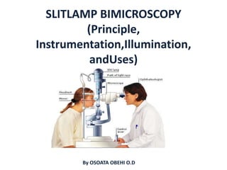
Slitlamp bimicroscopy
- 2. OUTLINE • INTRODUCTION • HISTORY • WORKING PRINCIPLE • COMPONENTS OF A SLITLAMP • ILUMINATION SYSTEM • OBSERVATION SYSTEM • MECHANICAL SYSTEM • ILLUMINATION TECHNIQUES AND THEIR APPLICATION • OCULAR TISSUES AND POSSIBLE ABNORMALITIES • RECORDING • ACCESSORIES USED WITH THE SLITLAMP
- 3. Introduction • The slit lamp is the most flexible and widely- used instrument for ophthalmic diagnosis. it enables the practitioner to observe the living tissue of eye under magnification and allows quantitative measurements and photography of every part for documentation.
- 4. Ocular Structures that can be examined with the slitlamp bimicroscope include: • Eyelid • Cornea • Sclera • Conjunctiva • Iris • Aqueous • Natural crystalline lens • Anterior vitreous
- 5. Other Uses Of Slitlamp Bimicrosope: • Fundus examination with the use of high power lenses eg +60 ,+90, -58D and -65D in form of a contact lens. • Mechanical and optical support for many accessories eg Tonometer, Goniosopy, cameras • Beam delivery devices for visually controlled laser treatment eg laser photocoagulation.
- 6. HISTORY Alvar Gullstrand 1911 created first slit projector Otto Henker devised an arm to support Czapski corneal loupe. Hans Goldmann 1933 created a joystick to focus the two components this evolved the model for today's HAAG STREIT slit lamps . Wilhelm Comberg 1933 created vertically downward illumination system Hans Littmann in 1953 combined both Goldmann and Comberg's systems thereby creating the model for today's ZEISS slit lamps.
- 8. 1940 Hamblin UK Slitlamp Littmann Type Zeiss Slit lamp
- 10. ZEISS SLITLAMP
- 12. WORKING PRINCIPLE An intense light beam entering a dark room through a tight window slit causing dust particles become visible which could never be seen if the room were brightly illuminated. With a narrow slit and a sufficiently small aperture angle, the illumination beam has a shape defined by two knife edges placed end to end. When the beam passes through transparent structures in the anterior part of the eye, it is scattered at microscopically small inhomogeneities. The slit-shaped scattering image of the structures is referred to as the optical section.
- 13. Figure 6.38 (a) Front view of an eye in normal (diffuse) illumination. The cornea can only be recognized via reflections (Purkinje image). (b) Front view of the eye with slit illumination in which the scattering images provide an optical sectioning. With such an illumination technique, we can also see the cross- sections of cornea and eye lens.
- 14. MAJOR COMPONENTS OF A SLITLAMP ILLUMINATION SYSTEM 1 OBSERVATION SYSTEM 2 MECHANICAL SYSTEM 3
- 15. ILLUMINATION SYSTEM A bright ,focal source of light with a slit mechanism Provides an illumination of 2*10^5 to 4*10^5lux. The beam of light can be changed in intensity,height,width,direction or angle and color during the examination with the flick of lever.
- 16. Condensing lens system: Consist of a couple of planoconvex lenses with their convex surface in apposition. Slit and other diapharm: Height and width of slit can be varied by using knobs. Projection lens: Form an image of slit at eye. Advantages 1.keeps the aberration of lens down. 2.increase the depth of focus of slit.
- 17. Light sources: tungsten and halogen filament bulbs are used although , LEDs are increasingly replacing the classic light sources. Formation of the slit image: Based on Kohler-type illumination.
- 18. FORMATION OF SLIT IMAGE
- 20. OBSERVATION SYSTEM Includes the eye piece and objective lenses. The objective lens consists of two planoconvex lenses with their convexities put together providing a composite power of +22D. Binocular Microscope consists of two eye piece each having a +10D lens. Prisms are placed between the objective and eyepiece to reinvert the image. Most slit lamp provide a range of magnification from 6x to 50x.
- 21. Optics of Observation System
- 22. MECHANICAL SYSTEM • Includes the mechanical adjustments and rests to aid ease of examination and better assessment of ocular tissues. • Components of the mechanical system : Three- coordinate Joystick Headrest Chin rest Rotary axis Canthus alignment Magnification and Filter Changers etc.
- 23. Rotary Axis biomicroscope Changing filters Magnification changer Patient positioning
- 25. ILLUMINATION TECHNIQUES • Diffuse illumination • Direct illumination o Parallilepiped o Optic section o Conical(pinpoint) o Tangential o Specular reflection • Indirect illumination o Retro-illumination o Sclerotic scatter o Transillumination o Proximal illumination
- 26. DIFFUSE ILLUMINATION • Angle between microscope and illumination system should be 30-45 degree. • Slit width should be widest. • Filter to be used is diffusing filter. • Magnification: low to medium • Illumination: medium to high. Applications: – General view of anterior of eye: lids,lashes,sclera,cornea ,iris, pupil, – Gross pathology and media opacities – Contact lens fitting. – Assessment of lachrymal reflex.
- 28. • Involves placing the light source at an angle of about 40-50 degree from microscope. • This arrangement permits both light beam and microscope to be sharply focused on the ocular tissue being observed. • Wide beam direct illumination is commonly used as a preliminary technique to evaluate large area • it is particularly suitable for assessment of cataracts,scars,nerves,vessels etc. • It is also of great importance for the determination of stabilization of axis of toric contact lens.
- 29. (a) Observed cross-section of the cornea (framed) with direct focal illumination and . (b) corresponding schematic cross-section of the (sliced) cornea
- 30. TYPES OF DIRECT ILLUMINATION TECHNIQUES Parallelepiped: Constructed by narrowing the beam to 1-2mm in width to illuminate a rectangular area of cornea. Microscope is placed directly in front of patients cornea. Light source is approximately 45 degree from straight ahead position. Applications: Used to detect and examine corneal structures and defects. Used to detect corneal striae that develop when corneal edema occurs with hydrogel lens wear and in keratoconus. Higher magnification than that used with wide beam illumination is preferred to evaluate both depth and extent of corneal, scarring or foreign bodies.
- 31. Click to add text
- 32. Conical beam(pinpoint) – Produced by narrowing the vertical height of a parallelepiped to produce a small circular or square spot of light. – Light source is 45-60 degree temporally and directed into pupil. – Magnification: high(16-25x) Application Used to examined the transparency of the anterior chamber for floating cells in anterior uveitis.
- 34. Optic section 1 Optic section is a very thin parallelepiped and optically cuts a very thin slice of the cornea. 2 Angle between illuminating and viewing path is 45 degree. 3 With wider slit their extension and shape are visible more clearly. 4 Magnification: maximum. 5 Application 6 Assess depth and portion of obejects eg foreign body and during contact lens fitting 7 Examination of AC depth is performed by wider slit width 1-3mm .
- 35. Used to localize: • Nerve fibers • Blood vessels • Infiltrates • Cataracts • AC depth. Optical section of lens
- 36. Tangential illumination • A narrow light beam is projected almost paralell along the structure to be observed. • Elevated structures are visible by shadowing • Illumination angle: 90 degree. • Medium –wide beam of moderate height is used. • Magnification of 10-25x Application: • Anterior and posterior cornea • Elevated abnormalities, changes in the iris, cysts and tumors. • Anterior lens (especially useful for viewing pseudoexfolation).
- 38. Specular reflection • Angle of illuminator to microscope must be equal and opposite. Each should be 30 degrees apart. • Angle of light should be moved until a very bright reflex obtained from corneal surface is called zone of specular reflection. • Under specular reflection anterior corneal surface appears as white uniform surface and corneal endothelium takes on a mosaic pattern.
- 39. • Application: • Evaluate general appearance of corneal endothelium • Lens surfaces • Cornea endothelium Example of tangential illumination (iris). Example of specular reflection.
- 40. INDIRECT ILLUMINATION The beam is focused in an area adjacent to ocular tissue to be observed hence light reflected by internal structures illuminates structure to be examined. The axis of the slit light is ±4°horizontally away from the normal position. Magnification: 12x and above
- 41. • Main application: Examination of objects in direct vicinity of corneal areas of reduced transparency eg, infiltrates, corneal scars, deposits, epithelial and stromal defects.
- 42. OCULAR TISSUE POSIBLE ABNORMALITIES GLOBE Irregular size shape or position (microphthalmus, bupthalmos, strabismus) ORBIT Gross anatomical abnormalities (endopthalmos, exophthalmos, palpable masses, crepitus) EYELIDS Anatomic (entropion, ectropion,eublepharon, trichiasis), Introduced(lacerations, notches), Dermal(dermatitis, erythema, alopecia, depigmentation, crusts, ulcers), Glandular(meibomianitis) abnormalities NASOLACRIMAL APPARATUS Discharge(serus, mucus, encrusted) obstructed or impeforated punta, masses within canaliculi SCLERA Vascular injection,Hemorrhage, cellular infiltration,masses CONJUCTIVA Hyperemia, hemorrhage, chemosis, folicularization, chemosis, symblepharon, cellular infiltration, massses. CORNEA Microcornea, edema, laceration, fibrosis, vascularization, cellular infiltrartion, iris prolapse, nodules etc ANTERIOR CHAMBER Depth, hyphema, hypopyon, iris cysts, vitreous prolapse, lens luxation,fibrous clots, persistent pupilary membranes etc IRIS Thickening, synechae,hyperpigmentation, rubeosis iris,
- 43. RECORDING OCULAR TISSUE RE LE GLOBE NORMAL NORMAL ORBIT NORMAL NORMAL EYELIDS NORMAL NORMAL NASOLACRIMAL APPARATUS NORMAL NORMAL SCLERA NORMAL NORMAL CONJUCTIVA CLEAR CLEAR CORNEA CLEAR CLEAR ANTERIOR CHAMBER DEEP DEEP IRIS NORMAL NORMAL LENS CLEAR CLEAR Ensure you record the type of abnormalities seen in case present.
- 44. SOME OPTICAL ASSESORIES USED WITH THE SLITLAMP Scleral lens +90D volk lens +78D Volk lens
- 45. Goldmann Applanation Tonometer Gonio lens Ruby lens Image of Posterior eye examination
- 47. THANK YOU