SlideShare une entreprise Scribd logo
1  sur  2
Télécharger pour lire hors ligne
1. Introduction
• Vertical railway track irregularities may increase the vertical forces acting on the railway track.
• Track construction and maintenance faults as well as allowable track construction tolerances may generate
irregularities in the form of vertical deviations in the track profile along a length of track and can result in increased
vertical wheel forces.
• Aside from computerized techniques, there are also well-established semi-empirical equations such as those proposed
by Talbot, Clarke and Eisenmann among many others that allow the designers to estimate the impact forces.
• The applicability of the existing empirical methods is limited in scope due to particular track and railway vehicle
conditions that generated them. One cannot claim that an empirically developed equation applies to every other track
condition.
• The author attempts to overcome this shortcoming by developing an analytical method and an explicit analytical
equation to estimate the impact forces, based on the principle of energy conservation, rules of kinematics and a
new concept of impact reduction factor developed by the author earlier.
• The proposed method concentrates on the track conditions, track stiffness, and the rate of change of track profile
irregularity.
I S T A N B U L U N I V E R S I T Y
Department of Civil Engineering
APPLICATION OF A NEW CONCEPT AND A METHOD
TO ESTIMATE THE VERTICAL IMPACT FORCES ON RAILWAY TRACKS
DUE TO TRACK PROFILE IRREGULARITIES
Niyazi Özgür BEZGİN, Ph.D
Associate Professor, ozgur.bezgin@istanbul.edu.tr
4. Development of a new concept and a method to estimate the dynamic impact forces
• The level of impact as the wheels roll over the defective track length, relates to the time it takes to hypothetically
free-fall from the height of vertical deviation h, referred to as tfall and the time to traverse the defective track length
L, referred to as tpass.
• Part of the potential energy of the tributary axle mass that transfers into the track as it rolls down or climbs up the
variable profile is quantified by a parameter proposed as the “IMPACT REDUCTION FACTOR (f)”
𝐟 = 𝟏 −
𝐭 𝐟𝐚𝐥𝐥
𝐭 𝐩𝐚𝐬𝐬
If
𝐭 𝐟𝐚𝐥𝐥 < 𝐭 𝐩𝐚𝐬𝐬
𝐭 𝐟𝐚𝐥𝐥 = 𝐭 𝐩𝐚𝐬𝐬
𝐭 𝐟𝐚𝐥𝐥 > 𝐭 𝐩𝐚𝐬𝐬
than
𝟎 < 𝐟 ≤ 𝟏
𝐟 = 𝟎
𝐟 < 𝟎
→
Partial to full reduction
No reduction
Amplification
𝑡𝑓𝑎𝑙𝑙 =
2ℎ
𝑔
, 𝑡 𝑝𝑎𝑠𝑠 =
𝐿
𝑣
𝐟 = 1 −
tfall
tpass
= 1 −
2. h
g
L
v
= 𝟏 −
𝐕
𝐋
.
𝟐𝐡
𝐠
E1 = m. g. h + c − a
E2 = m. g. h + c − a − 𝐦. 𝐠. 𝐡. 𝐟
E3 =
1
2
k a + c c − a
h + c − a − f. h =
1
2
a+c c−a
a
2. a. h + 2. a. c − 2. a2
− 2. a. f. h = c2
− a2
a2
+ 2. a. h. 1 − f − 2. a2
= c2
− 2. a. c
2. a. h. 1 − f − 2. a2
= c − a 2
− a2
2. a. h. (1 − f) = c − a
𝐜 = 𝐚 𝟏 + 𝟐𝐡
𝐚 (𝟏 − 𝐟)
𝐅𝐢 = 𝐤. 𝐜 = k. a. 1 + 2h
a (1 − f)
= 𝐅𝐬. 𝟏 + 𝟐𝐡
𝐚 (𝟏 − 𝐟)
Impact force factor proposed by Bezgin (KB)
𝐊 𝐁 = 𝟏 + 𝟐𝐡
𝐚 (𝟏 − 𝐟)
5. Variable profile and constant stiffness along the track
• The variation in the track profile generates a potential energy to the
tributary mass of the wheel.
a: Maximum static deflection of the track.
c: Maximum dynamic deflection of the track.
h: Difference in vertical track profile along a track length of L.
k: Track stiffness.
E: Potential energy.
• Depending on the impact reduction factor, this potential energy generates
the impact force of wheels on the track.
𝐦. 𝐠. 𝐡 + 𝐦. 𝐠. 𝐝𝐱
𝐜
𝟎
= 𝐤. 𝐱. 𝐝 𝐱
𝐜
𝟎
m. g. h + c =
1
2
. k. c2
h + c =
1
2.a
. c2
2. a. h + 2. c. a = c2
2. a. h = c − a 2
− a2
a2
. 1 + 2.h
a = c − a 2
c = a. 1 + 1 + 2.h
a
Fi = k. c = k. a. 1 + 1 + 2.h
a
𝐅𝐢 = 𝐅𝐬. 𝟏 + 𝟏 + 𝟐. 𝐡
𝐚 = 𝐅𝐬. 𝐊
2. Constant profile and stiffness along the track
• Given that the train wheels are perfectly circular, a perfectly
level track with a constant stiffness, would not induce
dynamic impact forces.
• The potential energy of the tributary mass of the wheels
would not change with respect to the deformed or
undeformed states of the track between 1 and 2.
3. Impact force on the track induced by the rate of change of potential energy of the axle mass
• Let us first consider the development of an impact force induced by a free-falling mass on an undamped linear –
elastic spring through the principle of energy conservation.
Train speed (km/hour) (mph)
0 25 50 100 150 200 250 300
0 16 31 62 93 124 155 186
tfall/tpass, L=30.5 m (100 ft)
0.00 0.00 0.00 0.00 0.00 0.00 0.00 0.00
0.00 0.01 0.02 0.04 0.06 0.08 0.10 0.12
0.00 0.01 0.03 0.06 0.09 0.12 0.15 0.17
0.00 0.02 0.04 0.07 0.11 0.14 0.18 0.21
0.00 0.02 0.04 0.08 0.12 0.16 0.21 0.25
0.00 0.02 0.05 0.09 0.14 0.18 0.23 0.28
Train speed (km/hour) (mph)
0 25 50 100 150 200 250 300
0 16 31 62 93 124 155 186
f = 1- tfall/tpass
1.00 1.00 1.00 1.00 1.00 1.00 1.00 1.00
1.00 0.99 0.98 0.96 0.94 0.92 0.90 0.88
1.00 0.99 0.97 0.94 0.91 0.88 0.85 0.83
1.00 0.98 0.96 0.93 0.89 0.86 0.82 0.79
1.00 0.98 0.96 0.92 0.88 0.84 0.79 0.75
1.00 0.98 0.95 0.91 0.86 0.82 0.77 0.72
Train speed (km/hour) (mph)
0 25 50 100 150 200 250 300
0 16 31 62 93 124 155 186
KB
1.00 1.00 1.00 1.00 1.00 1.00 1.00 1.00
1.00 1.14 1.20 1.29 1.35 1.41 1.45 1.50
1.00 1.24 1.34 1.48 1.59 1.68 1.76 1.84
1.00 1.33 1.46 1.65 1.80 1.92 2.03 2.13
1.00 1.41 1.57 1.81 1.99 2.15 2.28 2.41
1.00 1.48 1.68 1.96 2.17 2.36 2.52 2.66
h
(mm)
(in)
h/a for
a=10
mm
(0.4 in)
tfall
(s)
0 0.0 0.000
10 (0.4) 1.0 0.045
20 (0.8) 2.0 0.064
30 (1.2) 3.0 0.078
40 (1.6) 4.0 0.090
50 (2.0) 5.0 0.101
h
(mm) (in)
h/a for
a=10
mm
(0.4 in)
0 0.0
10 (0.4) 1.0
20 (0.8) 2.0
30 (1.2) 3.0
40 (1.6) 4.0
50 (2.0) 5.0
h
(mm) (in)
h/a for
a=10
mm
(0.4 in)
0 0.0
10 (0.4) 1.0
20 (0.8) 2.0
30 (1.2) 3.0
40 (1.6) 4.0
50 (2.0) 5.0
Train speed (km/hour) (mph)
0 25 50 100 150 200 250 300
0 16 31 62 93 124 155 186
tfall/tpass, L=15.2 m (50 ft)
0.00 0.00 0.00 0.00 0.00 0.00 0.00 0.00
0.00 0.02 0.04 0.08 0.12 0.16 0.21 0.25
0.00 0.03 0.06 0.12 0.17 0.23 0.29 0.35
0.00 0.04 0.07 0.14 0.21 0.29 0.36 0.43
0.00 0.04 0.08 0.16 0.25 0.33 0.41 0.49
0.00 0.05 0.09 0.18 0.28 0.37 0.46 0.55
Train speed (km/hour) (mph)
0 25 50 100 150 200 250 300
0 16 31 62 93 124 155 186
f = 1-tfall/tpass
1.00 1.00 1.00 1.00 1.00 1.00 1.00 1.00
1.00 0.98 0.96 0.92 0.88 0.84 0.79 0.75
1.00 0.97 0.94 0.88 0.83 0.77 0.71 0.65
1.00 0.96 0.93 0.86 0.79 0.71 0.64 0.57
1.00 0.96 0.92 0.84 0.75 0.67 0.59 0.51
1.00 0.95 0.91 0.82 0.72 0.63 0.54 0.45
Train speed (km/hour) (mph)
0 25 50 100 150 200 250 300
0 16 31 62 93 124 155 186
KB
1.00 1.00 1.00 1.00 1.00 1.00 1.00 1.00
1.00 1.20 1.29 1.41 1.50 1.57 1.64 1.70
1.00 1.34 1.48 1.68 1.84 1.96 2.08 2.18
1.00 1.46 1.65 1.92 2.13 2.31 2.46 2.60
1.00 1.57 1.81 2.15 2.41 2.62 2.81 2.99
1.00 1.68 1.96 2.36 2.66 2.92 3.14 3.35
Train speeds (v) Pass-time, tp=L/v (s)
km/h mph m/s ft/s
For L=15.2
m (50 ft)
For L=30.5
m (100 ft)
For L=45.7
m (150 ft)
For L=61 m
(200 ft)
0 0 0.0 0.0 Infinite Infinite Infinite Infinite
25 16 6.9 22.8 2.19 4.39 6.58 8.78
50 31 13.9 45.6 1.10 2.19 3.29 4.39
100 62 27.8 91.1 0.55 1.10 1.65 2.19
150 93 41.7 136.7 0.37 0.73 1.10 1.46
200 124 55.6 182.3 0.27 0.55 0.82 1.10
250 155 69.4 227.8 0.22 0.44 0.66 0.88
300 186 83.3 273.4 0.18 0.37 0.55 0.73
𝐟 = 𝟏 −
𝐭 𝐟𝐚𝐥𝐥
𝐭 𝐩𝐚𝐬𝐬
𝐊 𝐁 = 𝟏 + 𝟐𝐡
𝐚 (𝟏 − 𝐟)
If
𝟎 < 𝐟 ≤ 𝟏
𝐟 = 𝟎
𝐟 < 𝟎
→
Partial to full reduction
No reduction
Amplification
1. Occurrence of impact forces relates to combined influence of track irregularities and track stiffness.
2. Along a track with a very high stiffness, even a minute vertical deviation from the track profile may produce a high
impact force on the track.
3. Whether a certain level of vertical deviation along a misaligned track length makes the track, a poor track or a good
track is also a matter of the track stiffness and the resulting static deflection.
4. The base limit condition for h/a=0 represents perfect track alignment and therefore the track does not induce
impact forces on rolling wheels.
5. Note that the estimated impact factors by the proposed method decrease as the defective track length along which
a given value of vertical deviation develops increases.
6. The effect of a vertical deviation (h) on the developing impact also relates to its ratio to the static track deflection.
7. The proposed method by Bezgin responds to the particular conditions of track (h, a and L) and provide different
estimates for differing conditions.
8. The proposed equation suggests that if the track stiffness were so high to produce so small static deflections, the
high track stiffness would amplify the impact effect of a very small vertical irregularity along the track.
Impact reduction factor (f)
Impact factor proposed by Bezgin (KB)
6. Application of the proposed method to estimate impact forces
8. Conclusions
7. Impact factor estimates of a selection of semi-empirical methods

Contenu connexe

Tendances

The active suspension system with hydraulic actuator for half car model analy...
The active suspension system with hydraulic actuator for half car model analy...The active suspension system with hydraulic actuator for half car model analy...
The active suspension system with hydraulic actuator for half car model analy...
eSAT Publishing House
 
Aeroelasticity_A_R_10241445
Aeroelasticity_A_R_10241445Aeroelasticity_A_R_10241445
Aeroelasticity_A_R_10241445
Amit Ramji ✈
 

Tendances (20)

3.2 KINEMATIC ANALYSIS ON GEAR TRAIN
3.2 KINEMATIC ANALYSIS ON GEAR TRAIN3.2 KINEMATIC ANALYSIS ON GEAR TRAIN
3.2 KINEMATIC ANALYSIS ON GEAR TRAIN
 
4.2 follower motion
4.2 follower motion4.2 follower motion
4.2 follower motion
 
3.1 GEAR TRAINS
3.1 GEAR TRAINS3.1 GEAR TRAINS
3.1 GEAR TRAINS
 
Four-Wheel Vehicle Suspension Model
Four-Wheel Vehicle Suspension ModelFour-Wheel Vehicle Suspension Model
Four-Wheel Vehicle Suspension Model
 
3.3 NUMERICAL BASED ON GEAR TRAINS
3.3 NUMERICAL BASED ON GEAR TRAINS3.3 NUMERICAL BASED ON GEAR TRAINS
3.3 NUMERICAL BASED ON GEAR TRAINS
 
The active suspension system with hydraulic actuator for half car model analy...
The active suspension system with hydraulic actuator for half car model analy...The active suspension system with hydraulic actuator for half car model analy...
The active suspension system with hydraulic actuator for half car model analy...
 
6.1 synthsis of the mechanism
6.1 synthsis of the mechanism6.1 synthsis of the mechanism
6.1 synthsis of the mechanism
 
Fly wheel apparatus(a)
Fly wheel apparatus(a)Fly wheel apparatus(a)
Fly wheel apparatus(a)
 
Flywheel Apparatus1.doc
Flywheel Apparatus1.docFlywheel Apparatus1.doc
Flywheel Apparatus1.doc
 
2.3 worm and worm wheel
2.3 worm and worm wheel2.3 worm and worm wheel
2.3 worm and worm wheel
 
4.9 polynomial cam
4.9 polynomial cam4.9 polynomial cam
4.9 polynomial cam
 
Turning moment-diagram-flywheel
Turning moment-diagram-flywheelTurning moment-diagram-flywheel
Turning moment-diagram-flywheel
 
flywheel
 flywheel flywheel
flywheel
 
Fly wheel(2).docx
Fly wheel(2).docxFly wheel(2).docx
Fly wheel(2).docx
 
MET 305 tutorial_5-gear_train
MET 305 tutorial_5-gear_trainMET 305 tutorial_5-gear_train
MET 305 tutorial_5-gear_train
 
Aeroelasticity_A_R_10241445
Aeroelasticity_A_R_10241445Aeroelasticity_A_R_10241445
Aeroelasticity_A_R_10241445
 
Dynamics of Machines: Question bank unitwise from vtu old question papers
Dynamics of Machines: Question bank unitwise from vtu old question papersDynamics of Machines: Question bank unitwise from vtu old question papers
Dynamics of Machines: Question bank unitwise from vtu old question papers
 
Gear train
Gear trainGear train
Gear train
 
brakes and dynamometer
brakes and dynamometerbrakes and dynamometer
brakes and dynamometer
 
Gears & Gear Trains
Gears & Gear TrainsGears & Gear Trains
Gears & Gear Trains
 

Similaire à 97th transportation research board meeting presentation-poster session 583

High Bandwidth suspention modelling and Design LQR Full state Feedback Contro...
High Bandwidth suspention modelling and Design LQR Full state Feedback Contro...High Bandwidth suspention modelling and Design LQR Full state Feedback Contro...
High Bandwidth suspention modelling and Design LQR Full state Feedback Contro...
Idabagus Mahartana
 

Similaire à 97th transportation research board meeting presentation-poster session 583 (20)

Cetra 2018 970 Bezgin_final
Cetra 2018 970 Bezgin_finalCetra 2018 970 Bezgin_final
Cetra 2018 970 Bezgin_final
 
Traction Mechanics
Traction MechanicsTraction Mechanics
Traction Mechanics
 
97th Transportation Research Board Meeting - Presentation Lectern Session 234
97th Transportation Research Board Meeting - Presentation Lectern Session 23497th Transportation Research Board Meeting - Presentation Lectern Session 234
97th Transportation Research Board Meeting - Presentation Lectern Session 234
 
Chapter 2 Track Geometry.pptx
Chapter 2 Track Geometry.pptxChapter 2 Track Geometry.pptx
Chapter 2 Track Geometry.pptx
 
speed time curve (1).pptx
speed time curve (1).pptxspeed time curve (1).pptx
speed time curve (1).pptx
 
Chapter 2 track geometrics and its maintainance
Chapter 2 track geometrics and its maintainanceChapter 2 track geometrics and its maintainance
Chapter 2 track geometrics and its maintainance
 
Quick return mechanism
Quick return mechanismQuick return mechanism
Quick return mechanism
 
Cam mech
Cam mechCam mech
Cam mech
 
AutomaticClutchEAC
AutomaticClutchEACAutomaticClutchEAC
AutomaticClutchEAC
 
Integrated inerter design and application
Integrated inerter design and applicationIntegrated inerter design and application
Integrated inerter design and application
 
Highway Design - Techniques for proper Planning and Execution .
Highway Design - Techniques for proper Planning and Execution . Highway Design - Techniques for proper Planning and Execution .
Highway Design - Techniques for proper Planning and Execution .
 
CE 533 Chapter 15.pptx
CE 533 Chapter 15.pptxCE 533 Chapter 15.pptx
CE 533 Chapter 15.pptx
 
Project 2b (1) (2)
Project 2b  (1) (2)Project 2b  (1) (2)
Project 2b (1) (2)
 
10 Geometric Design of Railway Track [Horizontal Alignment] (Railway Engineer...
10 Geometric Design of Railway Track [Horizontal Alignment] (Railway Engineer...10 Geometric Design of Railway Track [Horizontal Alignment] (Railway Engineer...
10 Geometric Design of Railway Track [Horizontal Alignment] (Railway Engineer...
 
Design of super elevation in Opencast Mine- a case study
Design of super elevation in Opencast Mine-  a case studyDesign of super elevation in Opencast Mine-  a case study
Design of super elevation in Opencast Mine- a case study
 
Worm amd worm wheel
Worm amd worm wheelWorm amd worm wheel
Worm amd worm wheel
 
Suspension_report
Suspension_reportSuspension_report
Suspension_report
 
IRJET- Shock Absorber Testing using FFT Analyzer with Dewesoft
IRJET- Shock Absorber Testing using FFT Analyzer with DewesoftIRJET- Shock Absorber Testing using FFT Analyzer with Dewesoft
IRJET- Shock Absorber Testing using FFT Analyzer with Dewesoft
 
High Bandwidth suspention modelling and Design LQR Full state Feedback Contro...
High Bandwidth suspention modelling and Design LQR Full state Feedback Contro...High Bandwidth suspention modelling and Design LQR Full state Feedback Contro...
High Bandwidth suspention modelling and Design LQR Full state Feedback Contro...
 
Rail track geometry
Rail track geometryRail track geometry
Rail track geometry
 

Dernier

Integrated Test Rig For HTFE-25 - Neometrix
Integrated Test Rig For HTFE-25 - NeometrixIntegrated Test Rig For HTFE-25 - Neometrix
Integrated Test Rig For HTFE-25 - Neometrix
Neometrix_Engineering_Pvt_Ltd
 
XXXXXXXXXXXXXXXXXXXXXXXXXXXXXXXXXXXXXXXXXXXXXXXXXXXX
XXXXXXXXXXXXXXXXXXXXXXXXXXXXXXXXXXXXXXXXXXXXXXXXXXXXXXXXXXXXXXXXXXXXXXXXXXXXXXXXXXXXXXXXXXXXXXXXXXXXXXXX
XXXXXXXXXXXXXXXXXXXXXXXXXXXXXXXXXXXXXXXXXXXXXXXXXXXX
ssuser89054b
 
1_Introduction + EAM Vocabulary + how to navigate in EAM.pdf
1_Introduction + EAM Vocabulary + how to navigate in EAM.pdf1_Introduction + EAM Vocabulary + how to navigate in EAM.pdf
1_Introduction + EAM Vocabulary + how to navigate in EAM.pdf
AldoGarca30
 
Call Girls in South Ex (delhi) call me [🔝9953056974🔝] escort service 24X7
Call Girls in South Ex (delhi) call me [🔝9953056974🔝] escort service 24X7Call Girls in South Ex (delhi) call me [🔝9953056974🔝] escort service 24X7
Call Girls in South Ex (delhi) call me [🔝9953056974🔝] escort service 24X7
9953056974 Low Rate Call Girls In Saket, Delhi NCR
 
"Lesotho Leaps Forward: A Chronicle of Transformative Developments"
"Lesotho Leaps Forward: A Chronicle of Transformative Developments""Lesotho Leaps Forward: A Chronicle of Transformative Developments"
"Lesotho Leaps Forward: A Chronicle of Transformative Developments"
mphochane1998
 

Dernier (20)

Thermal Engineering-R & A / C - unit - V
Thermal Engineering-R & A / C - unit - VThermal Engineering-R & A / C - unit - V
Thermal Engineering-R & A / C - unit - V
 
Online electricity billing project report..pdf
Online electricity billing project report..pdfOnline electricity billing project report..pdf
Online electricity billing project report..pdf
 
COST-EFFETIVE and Energy Efficient BUILDINGS ptx
COST-EFFETIVE  and Energy Efficient BUILDINGS ptxCOST-EFFETIVE  and Energy Efficient BUILDINGS ptx
COST-EFFETIVE and Energy Efficient BUILDINGS ptx
 
Unleashing the Power of the SORA AI lastest leap
Unleashing the Power of the SORA AI lastest leapUnleashing the Power of the SORA AI lastest leap
Unleashing the Power of the SORA AI lastest leap
 
HAND TOOLS USED AT ELECTRONICS WORK PRESENTED BY KOUSTAV SARKAR
HAND TOOLS USED AT ELECTRONICS WORK PRESENTED BY KOUSTAV SARKARHAND TOOLS USED AT ELECTRONICS WORK PRESENTED BY KOUSTAV SARKAR
HAND TOOLS USED AT ELECTRONICS WORK PRESENTED BY KOUSTAV SARKAR
 
A CASE STUDY ON CERAMIC INDUSTRY OF BANGLADESH.pptx
A CASE STUDY ON CERAMIC INDUSTRY OF BANGLADESH.pptxA CASE STUDY ON CERAMIC INDUSTRY OF BANGLADESH.pptx
A CASE STUDY ON CERAMIC INDUSTRY OF BANGLADESH.pptx
 
Integrated Test Rig For HTFE-25 - Neometrix
Integrated Test Rig For HTFE-25 - NeometrixIntegrated Test Rig For HTFE-25 - Neometrix
Integrated Test Rig For HTFE-25 - Neometrix
 
PE 459 LECTURE 2- natural gas basic concepts and properties
PE 459 LECTURE 2- natural gas basic concepts and propertiesPE 459 LECTURE 2- natural gas basic concepts and properties
PE 459 LECTURE 2- natural gas basic concepts and properties
 
FEA Based Level 3 Assessment of Deformed Tanks with Fluid Induced Loads
FEA Based Level 3 Assessment of Deformed Tanks with Fluid Induced LoadsFEA Based Level 3 Assessment of Deformed Tanks with Fluid Induced Loads
FEA Based Level 3 Assessment of Deformed Tanks with Fluid Induced Loads
 
A Study of Urban Area Plan for Pabna Municipality
A Study of Urban Area Plan for Pabna MunicipalityA Study of Urban Area Plan for Pabna Municipality
A Study of Urban Area Plan for Pabna Municipality
 
Hostel management system project report..pdf
Hostel management system project report..pdfHostel management system project report..pdf
Hostel management system project report..pdf
 
Moment Distribution Method For Btech Civil
Moment Distribution Method For Btech CivilMoment Distribution Method For Btech Civil
Moment Distribution Method For Btech Civil
 
XXXXXXXXXXXXXXXXXXXXXXXXXXXXXXXXXXXXXXXXXXXXXXXXXXXX
XXXXXXXXXXXXXXXXXXXXXXXXXXXXXXXXXXXXXXXXXXXXXXXXXXXXXXXXXXXXXXXXXXXXXXXXXXXXXXXXXXXXXXXXXXXXXXXXXXXXXXXX
XXXXXXXXXXXXXXXXXXXXXXXXXXXXXXXXXXXXXXXXXXXXXXXXXXXX
 
Orlando’s Arnold Palmer Hospital Layout Strategy-1.pptx
Orlando’s Arnold Palmer Hospital Layout Strategy-1.pptxOrlando’s Arnold Palmer Hospital Layout Strategy-1.pptx
Orlando’s Arnold Palmer Hospital Layout Strategy-1.pptx
 
1_Introduction + EAM Vocabulary + how to navigate in EAM.pdf
1_Introduction + EAM Vocabulary + how to navigate in EAM.pdf1_Introduction + EAM Vocabulary + how to navigate in EAM.pdf
1_Introduction + EAM Vocabulary + how to navigate in EAM.pdf
 
Call Girls in South Ex (delhi) call me [🔝9953056974🔝] escort service 24X7
Call Girls in South Ex (delhi) call me [🔝9953056974🔝] escort service 24X7Call Girls in South Ex (delhi) call me [🔝9953056974🔝] escort service 24X7
Call Girls in South Ex (delhi) call me [🔝9953056974🔝] escort service 24X7
 
"Lesotho Leaps Forward: A Chronicle of Transformative Developments"
"Lesotho Leaps Forward: A Chronicle of Transformative Developments""Lesotho Leaps Forward: A Chronicle of Transformative Developments"
"Lesotho Leaps Forward: A Chronicle of Transformative Developments"
 
DC MACHINE-Motoring and generation, Armature circuit equation
DC MACHINE-Motoring and generation, Armature circuit equationDC MACHINE-Motoring and generation, Armature circuit equation
DC MACHINE-Motoring and generation, Armature circuit equation
 
AIRCANVAS[1].pdf mini project for btech students
AIRCANVAS[1].pdf mini project for btech studentsAIRCANVAS[1].pdf mini project for btech students
AIRCANVAS[1].pdf mini project for btech students
 
Work-Permit-Receiver-in-Saudi-Aramco.pptx
Work-Permit-Receiver-in-Saudi-Aramco.pptxWork-Permit-Receiver-in-Saudi-Aramco.pptx
Work-Permit-Receiver-in-Saudi-Aramco.pptx
 

97th transportation research board meeting presentation-poster session 583

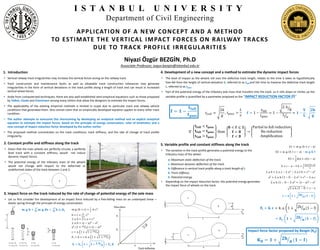
  • 1. 1. Introduction • Vertical railway track irregularities may increase the vertical forces acting on the railway track. • Track construction and maintenance faults as well as allowable track construction tolerances may generate irregularities in the form of vertical deviations in the track profile along a length of track and can result in increased vertical wheel forces. • Aside from computerized techniques, there are also well-established semi-empirical equations such as those proposed by Talbot, Clarke and Eisenmann among many others that allow the designers to estimate the impact forces. • The applicability of the existing empirical methods is limited in scope due to particular track and railway vehicle conditions that generated them. One cannot claim that an empirically developed equation applies to every other track condition. • The author attempts to overcome this shortcoming by developing an analytical method and an explicit analytical equation to estimate the impact forces, based on the principle of energy conservation, rules of kinematics and a new concept of impact reduction factor developed by the author earlier. • The proposed method concentrates on the track conditions, track stiffness, and the rate of change of track profile irregularity. I S T A N B U L U N I V E R S I T Y Department of Civil Engineering APPLICATION OF A NEW CONCEPT AND A METHOD TO ESTIMATE THE VERTICAL IMPACT FORCES ON RAILWAY TRACKS DUE TO TRACK PROFILE IRREGULARITIES Niyazi Özgür BEZGİN, Ph.D Associate Professor, ozgur.bezgin@istanbul.edu.tr 4. Development of a new concept and a method to estimate the dynamic impact forces • The level of impact as the wheels roll over the defective track length, relates to the time it takes to hypothetically free-fall from the height of vertical deviation h, referred to as tfall and the time to traverse the defective track length L, referred to as tpass. • Part of the potential energy of the tributary axle mass that transfers into the track as it rolls down or climbs up the variable profile is quantified by a parameter proposed as the “IMPACT REDUCTION FACTOR (f)” 𝐟 = 𝟏 − 𝐭 𝐟𝐚𝐥𝐥 𝐭 𝐩𝐚𝐬𝐬 If 𝐭 𝐟𝐚𝐥𝐥 < 𝐭 𝐩𝐚𝐬𝐬 𝐭 𝐟𝐚𝐥𝐥 = 𝐭 𝐩𝐚𝐬𝐬 𝐭 𝐟𝐚𝐥𝐥 > 𝐭 𝐩𝐚𝐬𝐬 than 𝟎 < 𝐟 ≤ 𝟏 𝐟 = 𝟎 𝐟 < 𝟎 → Partial to full reduction No reduction Amplification 𝑡𝑓𝑎𝑙𝑙 = 2ℎ 𝑔 , 𝑡 𝑝𝑎𝑠𝑠 = 𝐿 𝑣 𝐟 = 1 − tfall tpass = 1 − 2. h g L v = 𝟏 − 𝐕 𝐋 . 𝟐𝐡 𝐠 E1 = m. g. h + c − a E2 = m. g. h + c − a − 𝐦. 𝐠. 𝐡. 𝐟 E3 = 1 2 k a + c c − a h + c − a − f. h = 1 2 a+c c−a a 2. a. h + 2. a. c − 2. a2 − 2. a. f. h = c2 − a2 a2 + 2. a. h. 1 − f − 2. a2 = c2 − 2. a. c 2. a. h. 1 − f − 2. a2 = c − a 2 − a2 2. a. h. (1 − f) = c − a 𝐜 = 𝐚 𝟏 + 𝟐𝐡 𝐚 (𝟏 − 𝐟) 𝐅𝐢 = 𝐤. 𝐜 = k. a. 1 + 2h a (1 − f) = 𝐅𝐬. 𝟏 + 𝟐𝐡 𝐚 (𝟏 − 𝐟) Impact force factor proposed by Bezgin (KB) 𝐊 𝐁 = 𝟏 + 𝟐𝐡 𝐚 (𝟏 − 𝐟) 5. Variable profile and constant stiffness along the track • The variation in the track profile generates a potential energy to the tributary mass of the wheel. a: Maximum static deflection of the track. c: Maximum dynamic deflection of the track. h: Difference in vertical track profile along a track length of L. k: Track stiffness. E: Potential energy. • Depending on the impact reduction factor, this potential energy generates the impact force of wheels on the track. 𝐦. 𝐠. 𝐡 + 𝐦. 𝐠. 𝐝𝐱 𝐜 𝟎 = 𝐤. 𝐱. 𝐝 𝐱 𝐜 𝟎 m. g. h + c = 1 2 . k. c2 h + c = 1 2.a . c2 2. a. h + 2. c. a = c2 2. a. h = c − a 2 − a2 a2 . 1 + 2.h a = c − a 2 c = a. 1 + 1 + 2.h a Fi = k. c = k. a. 1 + 1 + 2.h a 𝐅𝐢 = 𝐅𝐬. 𝟏 + 𝟏 + 𝟐. 𝐡 𝐚 = 𝐅𝐬. 𝐊 2. Constant profile and stiffness along the track • Given that the train wheels are perfectly circular, a perfectly level track with a constant stiffness, would not induce dynamic impact forces. • The potential energy of the tributary mass of the wheels would not change with respect to the deformed or undeformed states of the track between 1 and 2. 3. Impact force on the track induced by the rate of change of potential energy of the axle mass • Let us first consider the development of an impact force induced by a free-falling mass on an undamped linear – elastic spring through the principle of energy conservation.
  • 2. Train speed (km/hour) (mph) 0 25 50 100 150 200 250 300 0 16 31 62 93 124 155 186 tfall/tpass, L=30.5 m (100 ft) 0.00 0.00 0.00 0.00 0.00 0.00 0.00 0.00 0.00 0.01 0.02 0.04 0.06 0.08 0.10 0.12 0.00 0.01 0.03 0.06 0.09 0.12 0.15 0.17 0.00 0.02 0.04 0.07 0.11 0.14 0.18 0.21 0.00 0.02 0.04 0.08 0.12 0.16 0.21 0.25 0.00 0.02 0.05 0.09 0.14 0.18 0.23 0.28 Train speed (km/hour) (mph) 0 25 50 100 150 200 250 300 0 16 31 62 93 124 155 186 f = 1- tfall/tpass 1.00 1.00 1.00 1.00 1.00 1.00 1.00 1.00 1.00 0.99 0.98 0.96 0.94 0.92 0.90 0.88 1.00 0.99 0.97 0.94 0.91 0.88 0.85 0.83 1.00 0.98 0.96 0.93 0.89 0.86 0.82 0.79 1.00 0.98 0.96 0.92 0.88 0.84 0.79 0.75 1.00 0.98 0.95 0.91 0.86 0.82 0.77 0.72 Train speed (km/hour) (mph) 0 25 50 100 150 200 250 300 0 16 31 62 93 124 155 186 KB 1.00 1.00 1.00 1.00 1.00 1.00 1.00 1.00 1.00 1.14 1.20 1.29 1.35 1.41 1.45 1.50 1.00 1.24 1.34 1.48 1.59 1.68 1.76 1.84 1.00 1.33 1.46 1.65 1.80 1.92 2.03 2.13 1.00 1.41 1.57 1.81 1.99 2.15 2.28 2.41 1.00 1.48 1.68 1.96 2.17 2.36 2.52 2.66 h (mm) (in) h/a for a=10 mm (0.4 in) tfall (s) 0 0.0 0.000 10 (0.4) 1.0 0.045 20 (0.8) 2.0 0.064 30 (1.2) 3.0 0.078 40 (1.6) 4.0 0.090 50 (2.0) 5.0 0.101 h (mm) (in) h/a for a=10 mm (0.4 in) 0 0.0 10 (0.4) 1.0 20 (0.8) 2.0 30 (1.2) 3.0 40 (1.6) 4.0 50 (2.0) 5.0 h (mm) (in) h/a for a=10 mm (0.4 in) 0 0.0 10 (0.4) 1.0 20 (0.8) 2.0 30 (1.2) 3.0 40 (1.6) 4.0 50 (2.0) 5.0 Train speed (km/hour) (mph) 0 25 50 100 150 200 250 300 0 16 31 62 93 124 155 186 tfall/tpass, L=15.2 m (50 ft) 0.00 0.00 0.00 0.00 0.00 0.00 0.00 0.00 0.00 0.02 0.04 0.08 0.12 0.16 0.21 0.25 0.00 0.03 0.06 0.12 0.17 0.23 0.29 0.35 0.00 0.04 0.07 0.14 0.21 0.29 0.36 0.43 0.00 0.04 0.08 0.16 0.25 0.33 0.41 0.49 0.00 0.05 0.09 0.18 0.28 0.37 0.46 0.55 Train speed (km/hour) (mph) 0 25 50 100 150 200 250 300 0 16 31 62 93 124 155 186 f = 1-tfall/tpass 1.00 1.00 1.00 1.00 1.00 1.00 1.00 1.00 1.00 0.98 0.96 0.92 0.88 0.84 0.79 0.75 1.00 0.97 0.94 0.88 0.83 0.77 0.71 0.65 1.00 0.96 0.93 0.86 0.79 0.71 0.64 0.57 1.00 0.96 0.92 0.84 0.75 0.67 0.59 0.51 1.00 0.95 0.91 0.82 0.72 0.63 0.54 0.45 Train speed (km/hour) (mph) 0 25 50 100 150 200 250 300 0 16 31 62 93 124 155 186 KB 1.00 1.00 1.00 1.00 1.00 1.00 1.00 1.00 1.00 1.20 1.29 1.41 1.50 1.57 1.64 1.70 1.00 1.34 1.48 1.68 1.84 1.96 2.08 2.18 1.00 1.46 1.65 1.92 2.13 2.31 2.46 2.60 1.00 1.57 1.81 2.15 2.41 2.62 2.81 2.99 1.00 1.68 1.96 2.36 2.66 2.92 3.14 3.35 Train speeds (v) Pass-time, tp=L/v (s) km/h mph m/s ft/s For L=15.2 m (50 ft) For L=30.5 m (100 ft) For L=45.7 m (150 ft) For L=61 m (200 ft) 0 0 0.0 0.0 Infinite Infinite Infinite Infinite 25 16 6.9 22.8 2.19 4.39 6.58 8.78 50 31 13.9 45.6 1.10 2.19 3.29 4.39 100 62 27.8 91.1 0.55 1.10 1.65 2.19 150 93 41.7 136.7 0.37 0.73 1.10 1.46 200 124 55.6 182.3 0.27 0.55 0.82 1.10 250 155 69.4 227.8 0.22 0.44 0.66 0.88 300 186 83.3 273.4 0.18 0.37 0.55 0.73 𝐟 = 𝟏 − 𝐭 𝐟𝐚𝐥𝐥 𝐭 𝐩𝐚𝐬𝐬 𝐊 𝐁 = 𝟏 + 𝟐𝐡 𝐚 (𝟏 − 𝐟) If 𝟎 < 𝐟 ≤ 𝟏 𝐟 = 𝟎 𝐟 < 𝟎 → Partial to full reduction No reduction Amplification 1. Occurrence of impact forces relates to combined influence of track irregularities and track stiffness. 2. Along a track with a very high stiffness, even a minute vertical deviation from the track profile may produce a high impact force on the track. 3. Whether a certain level of vertical deviation along a misaligned track length makes the track, a poor track or a good track is also a matter of the track stiffness and the resulting static deflection. 4. The base limit condition for h/a=0 represents perfect track alignment and therefore the track does not induce impact forces on rolling wheels. 5. Note that the estimated impact factors by the proposed method decrease as the defective track length along which a given value of vertical deviation develops increases. 6. The effect of a vertical deviation (h) on the developing impact also relates to its ratio to the static track deflection. 7. The proposed method by Bezgin responds to the particular conditions of track (h, a and L) and provide different estimates for differing conditions. 8. The proposed equation suggests that if the track stiffness were so high to produce so small static deflections, the high track stiffness would amplify the impact effect of a very small vertical irregularity along the track. Impact reduction factor (f) Impact factor proposed by Bezgin (KB) 6. Application of the proposed method to estimate impact forces 8. Conclusions 7. Impact factor estimates of a selection of semi-empirical methods