1. Landis & Gyr
Design Services Department – Information Release Procedure
VER 5.0 DRAFT
MANUFACTURING SERVICES GUIDELINE
1. PAPERLESS SYSTEM FOR DRAWING RELEASE
1.1 It is the Intention of Landis & Gyr Energy management ( UK ) Ltd to employ a
'Paperless System' where the issue of paperwork is restricted to absolute need and issue of
drawings to Tool-makers and assembly-houses which are unable to view paperless data. For
this reason all drawings ( as far as possible with present software ), will be kept on the Landis
& Gyr Novel network in the manner described below.
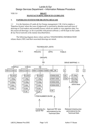
The following diagram shows where and how 'ENGINEERING INFORMATION'
release sheets ( RD ) and their associated drawings are stored.
PRIVATE APPS PUBLIC
GROUPS
RD
RD
10007 10008 10009
EI.DOC
1.dwg
2.dwg
3.doc
4.doc
5.xls
ITEM NUMBER ON RD
RD_OK
10000.DOC
10001.DOC
10002.DOC
10004.DOC
etc
4
104
1234
3 2
DRIVE MAPPING I:
active issue
Contents of a
typical 'RD'
Approved 'RD' area Released drawing area
TECHNOLOGY_0/SYS
administered by the
Technical Clerk Technical Clerk
administered by the
FIG. 1
0b.dwg
0-.dwg
0a.dwg
10010 10011
EI.DOC
1.dwg
2.dwg
3.doc
4.doc
5.xls
CHECK
10013 10012
EI.DOC
1.dwg
2.dwg
3.doc
4.doc
COMPILE
L&G EI_Release Proc.DOC Page 1 of 5 Author: P. Rouse
2. Landis & Gyr
Design Services Department – Information Release Procedure
2. RAISING AN E.I. NUMBER
2.1 The release of information through this system utilises the 'Windows shell'. An icon
which initiate the process is located in the 'MAIN' window, and looks like the one below :
FIG. 2
2.2 An EI number is taken out by double clicking the above icon. When the icon is
pressed the screen display turns black and the following display sequece begins :
Do you realy want to take out an RD number ? Y for yes; N for no
Please enter your name :
You have created directory number 100xx
Press any key when you have noted the RD number
2.3 When an RD number is taken out, a directory is automatically created by the program
in the area I:compile, in addtion a text file is appended with the RD number and the name
of the person who took it out.
2.4 The EI sheet is created using Microsoft Word, which is also an icon in the Windows
shell. In 'Word', select : 'FILE' followed by 'NEW'. This will give the following screen :
FIG. 3
2.5 From this screen select 'LG_EI', this brings you into the Word document and initiates
the macro which helps and prompts you to fill in the 'EI'.
2.6 Printing the document : when the 'change description' part of the form is filled in, it
automatically spills onto up to 5 further sheets. When printing you need to check how many
sheets have been used, and enter this in the number of pages. This is done by highlighting the
field and pressing F9 ( update field ), which brings up the dialog box..
2.7 When the documents have been completed, transfer them to the checkers work area :
I:CHECK100xx
2.8 Inform the checker that there are items to be checked using 'E-MAIL'.
or verbally until the system is set up.
2.9 The Checker is to inform the Draughtsman of any corrections that need to be made.
When the EI is acceptable it is then moved to : I:RD100xx.
L&G EI_Release Proc.DOC Page 2 of 5 Author: P. Rouse
3. Landis & Gyr
Design Services Department – Information Release Procedure
3. ADMINISTRATION OF RELEASED INFORMATION :
3.1 When an EI has been signed as 'O.K. PRODUCTION', the Technical Clerk will move
all the files belonging to the EI, from the release area, and file each drawing or data file under
each individual drawing number. This can be done with an appropriate file manager. The
released drawing area consists of sub directories for each drawing ( See fig. 1 ).
3.2 Each file in the checking area is named according to its position on the EI, e.g.
1.DWG, therefore each file will need to be renamed to the file name : 0-.dwg or 0a.dwg or
0b.dwg depending on its issue status and file type.
3.3 Most of the drawings being filed and renamed are MASTER DRAWINGS. Care
must be taken in renaming and filing all drawings.
3.4 In some cases the file is only a copy of the original in another format for viewing
purposes. It is the responsibility of the draughtsman / designer to move these master files to a
sub directory within the released drawing area, this should only be done when the 'EI' has
been signed as 'O.K. PRODUCTION'.
3.5 Modification : When a drawing is to be modified, the draughtsman / designer should
put a readme.txt file into the directory to state this fact, preferably with details of who is
doing the change and an indication of what the change will be. The master is not to be
removed but may be copied into an individuals work area.
4. VIEWING & DEFINITIONS OF FILE FORMATS :
Only 'a)' is available at present.
Under the paperless system, most drawings can be viewed at an appropriate viewing station.
These stations are located in the following places :
a) Manufacturing Services
b) Technology
c) Goods Inwards Inspection
d) Production
The following are definitions of the file names used in the Group : 'RD'
4.1 Within the 'RD' directory are sub directories which represent an 'EI' e.g.
I:RD10002
This sub directory will contain all of the document and drawing files associated with a
particular Engineering Information release. These are defined as follows :
L&G EI_Release Proc.DOC Page 3 of 5 Author: P. Rouse
4. Landis & Gyr
Design Services Department – Information Release Procedure
4.2 EI.DOC This is the Word document of the EI.
[ Disregard number before suffix, example only ]
4.3 1.DWG This would be a drawing file in the AutoCad format. The number at the
beginning of the file name will correspond to the item number on the EI
sheet, therefore there can be any number of drawings, e.g. 20.DRG.
4.4 8.DOC This includes all Process Instructions; Test Instructions; Supply
Specifications etc. which will be in Word format. The number at the
beginning of the file name will correspond to the item number on the EI
sheet, therefore there can be any number of documents.
4.5 12.XLS This includes any Excel parts lists ( under the old parts list system ), and any
other documents of this format. The number at the beginning of the file name
will correspond to the item number on the EI sheet, therefore there can be
any number of documents.
4.6 13.RPD Ashton Tate Rapid File, these are mainly for parts lists and assembly lists.
4.7 14.CDR These are Corel Draw files mainly for artworks and labels.
4.8 15.BMP These are bitmap files mainly for artworks and labels.
4.9 16.PCX These are files mainly for artworks and labels.
4.10 17.HGL This would be a drawing file in the HPGL plotting format. The number at
the beginning of the file name will correspond to the item number on the EI
sheet, therefore there can be any number of drawings, e.g. 15.DRG.
4.11 18.MDB This includes any O.T.I. and any other documents in Microsoft Access
format. The number at the beginning of the file name will correspond to the
item number on the EI sheet, therefore there can be any number of
documents.
4.12 Special cases : It is necessary to release Electronic data for the fabrication of
integrated circuits; test fixtures and Printed Circuit Boards. This information is necessarily in
the form of data which cannot be viewed in a way that will be of any use. In some cases this
will be in the form of a chip which is kept in a 'fire safe'. In this case the data may be
represented as a text document which describes what it is and where it can be found.
4.13 Paper Documents : Some existing documents are not in an electronic format, they are
either old drawings not in the CAD system; Artwork or Supply specs. etc. If this is a
document that is likely to be used around the company or it is likely to be modified in the
future, it may be worth digitising or scanning.
L&G EI_Release Proc.DOC Page 4 of 5 Author: P. Rouse
5. Landis & Gyr
Design Services Department – Information Release Procedure
L&G EI_Release Proc.DOC Page 5 of 5 Author: P. Rouse
5. SCANNING AND MEMORY :
5.1 Whilst Scanning is an obvious way of bringing drawings into the electronic system, it can
be extremely memory or disc intensive. Scanning a document should be done using Winword
as a basis in the following way :
5.2 Use the Landis & Gyr standard sheet as a basis.
5.3 Import text into the document were appropriate using Omnipage Direct.
5.4 Where drawings are part of a document use 'InsertFrame' to insert a frame the size that
the drawing is required to be.
5.5 Now use 'Insertobject' to enter WinwordPaint Brush and import the drawing. Remove all
drawing borders and any text that is already imported via Winwordfilescan. The result of
this is to reduce the disc space required by the document from between 20% to 80%.
6. BACKING UP
There will be backup of the 'I:' area onto 'Floptical disc' . The Manufacturing
Services Manager will be responsable for assigning a member of the department to do this.
The backup will be done on a weekly basis and will be updated by date.
The backup is run from the 'viewing station' located in Manufacturing Services and is
initiated through windows using the icon shown below
THIS BATCH FILE DOES THE BACKUP OF THE INFORMATION RELEASE AREA
XCOPY I:*.* E:DRAWBAK/S/E/D: the date of the prior to the last backup should be entered
here, to minimise the number of files copied.
7. SECURITY :
7.1 All AutoCad files are kept on the Technology Server of the Landis & Gyr computer
system. Access to the Landis & Gyr Novel network is only open to computers which have a
Novel Network card. This card cannot be used on the network without the use of a password
which is already set-up on the network by a network supervisor.
7.2 Access to directories files and programmes is also restricted by 'Access rights' which
are again only available through 'Rights' which are set-up up by either of the network
supervisors. N.B. the first two supervisors are most appropriate people to set-up access rights
for the Cad system.