SlideShare une entreprise Scribd logo
1  sur  22
DPC Final Report
Team One
A. Whittle, P. Achari, S. Moseley, J. Halper, E. McCarty, and C. Hunt,
ENGE 1216
May 5, 2016
Executive Summary:
This report discusses the development and selection of a drone concept that has the intended
purpose of wildlife observation, photography, and filmography. Current models on the market
are expensive, heavy, and noisy, and our solution is meant to address such problems.
In order to develop a successful concept for our drone, we first had to define criteria, constraints,
and a use case scenario. We decided that the drone should be quiet, compact, lightweight, be
capable of carrying a camera, and be able to fly above 100 ft. We chose these criteria and
constraints based on an interest in ease of use for the consumer and to avoid disturbing wildlife
and natural ecosystems. The drone is intended for wildlife observation, photography, and
filmography by amateur and professional wildlife photographers and is designed to disturb the
environment as little as possible.
Our team developed two different design alternatives to choose from. The viability of each
alternative was determined via decision matrices in which we weighed the importance of the
following criteria: aesthetics, weight, aerodynamics, time of flight, max height, size, cost, and lift
to drag ratio, and scored each alternative accordingly. We also built prototypes of the two
alternatives and glide tested them from various heights under controlled conditions. We decided
that the second alternative was the better option in accordance with our objectives based on the
results from the decision matrices and the prototype glide test results.
After choosing the better alternative, we developed a second prototype of the design. We also
created a MATLAB synthesis code to model the prototype’s trajectory after launch based on
assumptions about the prototype, launch mechanism, and launch environment, excluding the
mass prototype, which is a user-inputted value. To test the performance of this prototype, we
launched it out of a tube using pressurized water and recorded its angle of trajectory, flight
distance, and maximum height of flight. We also recorded pressure of the water, the amount of
water used for launch, and the wind speed at the date and time of launch. After launch testing the
prototype, we found that our test results did not match our synthesis code results. This
discrepancy can be attributed to the differences between the assumed values for variables in the
synthesis code and reality.
During this design project, our team developed designs for a wildlife photography drone. We
chose which design to use based on decision matrix values and prototype glide test results and
we used this design to develop a prototype for launch testing. After comparing our test results
with our synthesis code results, we found that they did not match, which was a result of certain
assumptions and limitations in the synthesis code.
Table of Contents
I. Introduction
II. Use Case/Requirements
A. Table 1
III. Ethics
IV. Design Alternatives
A. Figure 1
B. Figure 2
V. Design Evaluation
A. Table 2
B. Table 3
C. Figure 3
VI. Prediction and Testing
A. Figure 4
B. Figure 5
C. Figure 6.0
D. Figure 6.1
E. Table 4
F. Figure 7
VII. Conclusion
VIII. Limitations and Future Plans
IX. References
X. Appendices
A. Appendix A
B. Appendix B
C. Appendix C
D. Appendix D
E. Appendix E
F. Appendix F
G. Appendix G
I. Introduction
Drones are becoming increasingly popular in today’s society. They can be used to conduct many
different operations, ranging from surveillance to package delivery. Each new drone that comes
on the market is competing to be the best in its field, and shows improvements upon previous
models. The drone has become progressively more technologically advanced, with an emphasis
in capturing pictures and films.
During this project, our design team developed a drone production concept (DPC) that would be
used to photograph and film wildlife in various environments. The drone will be a low cost, high
performing, and mobile competitor compared to other observer drones in the field. Two different
concepts were used to decide what features to implement in the DPC design. Through prototype
testing, research, and the development of a decision matrix, the second concept was determined
be the option that best fit our criteria, constraints, and use case scenario. Through more testing,
synthesis code development, and prototype launches, our team was able to successfully develop
our DPC.
Drones have a variety of different uses. For example, unmanned aircrafts that can be controlled
from the ground are incredibly useful in search and rescue operations, as these machines can
record events happening in dangerous situations and relay a live feed to the proper authorities,
enabling them to take action. Drones can also be used to deliver packages, as surveillance
machines for public or private use, or as a security measure for any member of the public.
Drones can also be used in aerial photography and filmography, however there are certain
drawbacks and limitations to this if one’s intention is capturing images of wildlife in nature.
These shortcomings have encouraged our design team to develop and produce a drone that can
capture high definition footage and photographs of wildlife from the air.
II. Use Case/Requirements
Our team is a small technology startup company that has designed a drone production concept
with the target demographic of professional and amateur photographers/filmographers. The
drone will specialize in observing wildlife located in potentially dangerous terrain or sensitive
ecosystems such as forests, isolated mountains, and glaciers. Modern observer drones implement
high-quality cameras and are composed of aerodynamic materials in order to ensure their
success, however these products cost approximately $1400 and their average battery life is
approximately 28 minutes [1]. Furthermore, drones are known to emit noises loud enough to
disturb its surrounding environment. There are solutions being developed with the aim of cutting
down on noise emissions, such as reducing the amount of propellers or employing several small
motors instead of one large one, however this is still an issue in the drone market [2]. High cost
and high noise emission are examples of features that we would like to improve upon in
constructing our drone, as these design changes would allow our product to be more practical for
consumers. There are several parties that could be affected by the production and success of our
drone, including company employees, drone manufacturers, investors, consumers, and
consumers’ clients, which may include wildlife magazines, movie producers, and advertisers.
Our DPC is less than 10 inches in diameter and less than 30 inches in total length, as seen in
Figure 1. These size constraints were created to ensure that the drone will be large enough to
support a camera and all of its inner components, while being small enough to foster easy
mobility. Although our length constraint is 30 inches, we expect the drone to be much shorter to
allow for even easier mobility. Most drones that implement cameras are quadcopters as opposed
to our airplane-like drone design. When being transported, quadcopters must be kept in their
boxes to avoid damage, so we aimed for a design that is lightweight and compact so it can be
easily carried. The drone’s tube-like structure and folding wings will allow it to easily fit into a
bag while remaining intact. The bag can then be carried to the desired destination and the drone
can be launched by gently throwing it like a model airplane.
The DPC’s weight should be less than 3 pounds to also allow for easier mobility and
maneuverability. The drone must be easy to carry and alleviate as much work for the user as
possible. We chose a constraint of 3 pounds, as our competitor, the Phantom 4, is 3.04
pounds[1]. Although a small difference, this lighter weight will give our drone an edge over the
Phantom 4 and other competitors. A lighter weight will also improve the lift upon drag ratio.
Since weight is the force a gravity, as the mass increases the force of gravity on the DPC would
also increase. The only force counteracting the weight is lift. This means weight and lift and
directly proportional; if weight goes up, so does the lift needed to keep it in the air. [3]
Table 1: Criteria and Constraints
In order for our DPC to be useful to our consumers, our team had to define important flight
requirements. Our drone must be able to maneuver around obstacles, such as trees and hills, in
different situations, so we decided that the drone must be able to reach a height of at least 100 ft.
Ideally our drone will be able to fly higher than this in order to provide more space to maneuver
around tall objects, and to allow enough time to locate and record footage of surrounding
wildlife. Another concern is the drone’s time of flight. As previously stated, the Phantom 4 can
maintain an air time of 28 minutes. We would like our drone to maintain an airtime of at least an
hour, over twice that of the Phantom 4. This extra time will give the user a longer period of
uninterrupted filming.
In addition to size, weight, and flight guidelines, we also considered the drone’s retail and
manufacturing cost. A high quality drone for commercial use can cost over $1000, retail; the
Phantom 4 costs $1400, retail. The materials chosen for our DPC cost a total $578. We
determined we would use a magnesium structure similar to the Phantom 4 and an aluminum
composite body to ensure a durable, lightweight product. [4][5]. Our solution includes the
implementation of a GoPro, which would provide the drone with the same quality camera as that
on the Phantom 4, but at a much cheaper price of $500 per camera [6]. Overall, with the
inclusion of labor and design, our price point for the DPC will be $900 which is lower than our
target price of $1000 as seen in Figure 1.
Our drone requires a propulsion system to keep our it in the air and to provide extra lift. The
propulsion system will be electronic and will be able to be recharged after each use. We will also
develop an app based controlling system, similar to that of the Phantom 4, instead of a remote to
cut down on material and manufacturing costs. The app will come free with the purchase of the
DPC.
III. Ethics
In regards to the ethics of our drone, several issues must be addressed. The drone is meant to fly
high above the land it is surveying, which brings up the issue of privacy infringement. The
camera could capture feed of civilians without their knowledge while in the air, which is could
be considered an invasion of privacy, but this cannot necessarily be controlled; campers and
hikers are at most risk of this happening. Another possible issue arises with the idea of
trespassing. These drones could potentially be used to survey and gain information on restricted
properties, which is definitely not one of its intended purposes. Furthermore, studies show that
the heart rates of animals such as bears and penguins spike drastically when a drone flies by
overhead. "The magnitude of some of the heart-rate spikes were shocking," says Mark Ditmer, a
wildlife ecologist at the University of Minnesota. “To see heart rates go from 41 beats per minute
prior to the unmanned aerial vehicles' flight to over 160 beats per minute during the flight was
far beyond what we expected[7]." This is not an ideal situation, as we do not want our drone to
scare those which we are trying to observe. The discovery of a species in a specific area could
also include ethical issues; this could lead to invasive human presence in sensitive environments,
which would impede on the welfare of the affected wildlife. There is no way to avoid all of these
ethical issues, however, we can work diligently to minimize their effects.
IV. DesignAlternatives
In order to decide how to construct our drone, we developed two design alternatives. Our first
DPC, Figure 1, implements short, rectangular wings. The wings tilt downward and are connected
by a thin structure that pierces the 4-inch diameter body. Both the nose and the tail converge at a
point. Most of the weight is located towards the front of the bullet-shaped design. Instead of our
desired teardrop wing shape, we settled for a rectangular design, which ended up being our
closest option. This model lacks stabilizer fins, but does incorporate vertical tailfin. The lack of
this feature, as described by Life Science, will not allow “air to move faster over the top” of the
wing than the bottom of the wing[3]. Ultimately, the lack of stabilizer fins is what caused this
model to fail. The vertical fin located at the back does little to stabilize our model, as the model
is not heavy enough for the center of mass to be located under the center of the wings, which is
necessary in a design without stabilizer. Additionally, the durability of this alternative was poor
and its wings had a tendency to bend at undesirable angles.
Figure 1: Design concept #1
Our second concept, Figure 2, incorporates distinct, more desirable features. Instead of
possessing two wings that penetrate the fuselage, there is a single, large wing attached to the top
of the drone. The body of the drone is connected to the tail by a narrow section and the tail is
equipped with a tailfin and stabilizers. The purpose of the stabilizers is to “provide stability for
the aircraft, to keep it flying straight,” and to prevent an “up-and-down, or pitching, motion of
the aircraft nose” [8]. The designs’s sleek body and long wings are an improvement upon the
bulky body and choppy wings of the first alternative. This model exhibited improved lift,
stability, and durability compared to our first concept.
Figure 2: Design concept #2
Several different materials, many household, were used in the construction of our low-fidelity
DPC prototypes. Assembling the prototypes was fairly simple with some trial and error.
Although the two different concepts seem similar in design, the only features that these two
alternatives share are the tailfin, the propulsion system, and the camera. The camera is located at
the bottom of the body and is positioned downward to help capture photographs of the wildlife at
hand.
V. DesignEvaluation
After we developed two alternatives for our DPC, we evaluated each concept individually. We
did this by testing the lift to drag ratio (L/D) of each alternative by glide testing each prototype
from different heights in a controlled environment and recording the horizontal distance of each
throw. Then the L/D ratio was then calculated using the mass of the prototype along with the
throw distance. This gave us an approximation of the L/D ratio which helped us determine which
alternative performed better. The results from these glide tests can be seen in Table 2 below.
Table 2: Prototype Testing Results
In addition to prototype glide testing, we also used decision matrices, see Table 3, to help us
determine the preferred alternative for our DPC. In the first step of our concept selection, we
rated our established criteria against one another. We decided that certain criteria were more
important than others in our design. Our criteria, in order of decreasing importance, are: lift to
drag ratio, aerodynamics, time of flight, size, weight, maximum height, cost, and aesthetic.
These criteria were rated as such because it is essential that the performance of the plane is the
most important factor in our design. Lift to drag ratio is essential to the performance of the plane
which is why it carries the most weight in our decision matrix. Half our criteria were rated on a
scale of 1 to 10 and were objective criteria. Objective criteria included: aesthetics, aerodynamics,
size, and cost, and could not be quantified under the circumstances of developing the decision
matrices. We did not include time of flight and max height in our concept selection because they
could not be recorded in our testing exercise. The weight was rated on a scale of .001-1 pounds.
This was decided because it was determined that a 1 pound concept would be ideal. Lift to drag
ratio had been rated on a 1-40 ratio. This was determined because it was discovered in our
research that some planes get up to 40 on there L/D ratio.
After we scored each of our criteria on their corresponding scales, each score was normalized
against the highest and lowest values of its grading scale. Then the normalized scores were
weighted and added up. After adding up the weighted scores, we determined that our second
design concept was the more viable option. Since design 2 was the most viable option, we
decided to base out DPC off of it. As you can see in Figure 3, we kept the wings on top, and
horizontal and vertical stabilizers just as concept 2 had them.
Table 3- Decision Matrix
Figure 3: Concept 2 DPC drawing
VI. Prediction and Testing
Before approving our DPC, it was necessary to create a higher fidelity prototype of our design.
We constructed the DPC with our constraints, criteria, and use case scenario in mind. Our DPC
had to be less than 3 pounds, less than 30 inches long, less than 10 inches in diameter, be able to
fly higher than 100 feet, and have a flight time above an hour. The implementation of these
guidelines can be seen in Figures 4 & 5 . When planning our materials, we had to ensure that the
weight of our prototype was similar to our actual DPC to be able to get an idea of how well it
will perform at that weight. To keep the prototype lightweight, we made the wings out of
styrofoam. Though styrofoam is fairly weak alone, stacking multiple layers of styrofoam on top
of eachother allowed the wings to stay study and light. We also added horizontal and vertical
stabilizers which were also made out of styrofoam to keep our total mass to a minimum. We
attached one AA battery to the nose and one on the bottom of the prototype to shift its overall
center of mass and account for the weight of the motor. The batteries also allowed us to fix the
position of the wings which, in turn, created the best lift to drag ratio.
Figure 4: Top view of prototype concept #2 Figure 5: Side view of prototype concept #2
For our project we programed a synthesis code to approximate the launch of our prototype. This
code had multiple equations that simulated and graphed the results of different aspects of the
launch. The code calculates the vertical position, velocity, pressure, and time of flight of the
prototype with a time interval of .001 seconds. Once the calculations are complete, each array of
information is plotted on a graph relative to the time of flight. Lines 35, 55, 57, and 59, see
Figures 6.0 and 6.1, are lines of code that store each calculation into an array; “p” is the variable
for pressure, “v” for velocity, “y” for horizontal position, and “time” for time of flight. Each of
the following equations use different assumptions made in the beginning to calculate each
variable. Lines 7 - 20 in Figure 6.0 show what each variable stands for and the units of the
variable. This code was useful in that it gave us a model of what our prototype launch might be
like. Because the code is dependent on the empty mass of our prototype, we can predict a
suitable empty mass for our prototype that will generate the best results within the code’s
predetermined conditions. However, there are a number of limitations in the synthesis code.
First, predetermined conditions such as drag, volume of water, and volume of bottle are not
always constant as assumed in the synthesis code. Each bottle (plastic, 2 Liter) is shaped
differently depending on the manufacturer, and therefore prevents the “VT” variable from being
the same in all cases. The code is also written for uncommon units of measurement. The values
are in units such as “slugs”, and “feet per seconds squared” put a bit of a mathematical language
barrier between our code and metric users.
Figure 6.0 First half of Synthesis Code
Figure 6.1 Second half of synthesis code
Using the simulation from the synthesis code we predicted our prototype would reach a height of
about 100 ft with 300 mL, see Figure 7. After testing, we measured the actual launch height to be
about 42 for the 300ml launch. A few reasons why our test results did not match our prediction
from the synthesis code is because of variables such as wind, drag, and the structure of our
prototype. Within our code there was no wind variable to accommodate for. Therefore, the wind
during our launch, which was calm [9], could have affected the distance, height, and direction
our prototype traveled. The drag ratio in the synthesis code, as previously mentioned, only
accommodates for the body of the prototype. Though the body of the prototype heavily affects
drag variable, the wings, horizontal and vertical stabilizers, and nose of the prototype also
account for the drag value. Because of these additions, the drag value for our prototype was
larger than the drag value generated by the synthesis code. Another reason for the discrepancies
between our prediction and our results was structure of our prototype. The wings on our
prototype were not structurally stable, so when the prototype was launched, the wings were
knocked out of place. The synthesis code could have been modified to produce more realistic
predictions of our launch if we calculated the drag caused by the wings and included a wind
variable. Optimal test conditions would have clear weather with no wind with perfect launch
execution. If there was zero wind, our wings were structurally sound, and we accommodated for
the drag caused by our additions to the body of our prototype, then we could have have,
theoretically, achieved a perfect launch resulting in the same results as predicted.
Table 4: Launch data of prototype
Table 4- Launch
Data
Launch
Ml of
Water
Appx. Simulated
Altitude (ft.)
Actual Altitude
(ft.)
Horizontal
Distance (ft.)
1 200 87 18.75 22
2 300 97 40.5 69
3 300 97 45 43
Average 93.66 34.75 44.67
Figure 7. Graph of Predicted Altitude versus Time
VII. Conclusion
Our goal for this design project was to develop a drone product concept that would take high
quality, aerial footage of wildlife and natural environments. Our drones would be smaller,
cheaper, and more versatile than the drones that are currently on the market. Initially we
developed two concepts, one that has square wing design without stabilizers and another that has
a larger, sturdier design with stabilizers. After testing the concepts we decided, with the help of a
decision matrix, that the sturdier, larger wingspan design would fly better than its competing
design. After selection a concept, the design of that concept was translated into a prototype. This
prototype was then tested and it reached average horizontal distance of 45 feet from the launch
site. Overall, the initial selection of our concept and the building of our prototype leads us to
believe that our final product will fly with great performance and credibility.
VIII. Limitations and Future Plans
Our design strategy was limited in a few key ways. Our synthesis code projected our flight
height to be about 100 ft. In reality, this value was only about 34 ft. Our code was inaccurate in
predicting the launch data. This code was inaccurate primarily due to the drag coefficient in the
code. This value was set at .0007 and in reality was probably a lot higher. Another limitation of
our code was several uncontrolled variables during the launch. These variables include wind
speed and the weak structure of the prototype. This had a substantial impact on the performance
of the prototype.
In future testing it might be best to incorporate air resistance into the synthesis code. This would
give us a better prediction on the performance of the launch. We might also choose to build our
prototype out of different materials besides plastic bottles and foam board. This would ensure
that the prototype has a strong structure, durable enough for multiple, successful launches. We
could also alter the angle of launch in future tests. This could give us a greater distance on the
launch.
XI. References
[1] "DJI Phantom 4", PCMAG, 2016. [Online]. Available:
http://www.pcmag.com/review/342895/dji-phantom-4. [Accessed: 30- Apr- 2016].
[2] D. Hambling, "Silence of the drones: How to quiet that annoying aerial buzz", New Scientist,
2016. [Online]. Available: https://www.newscientist.com/article/dn27696-silence-of-the-drones-
how-to-quiet-that-annoying-aerial-buzz/. [Accessed: 05- May- 2016].
[3] “The Physics of Flight,” Flight. [Online]. Available at:
http://www.lcse.umn.edu/~bruff/bernoulli.html. [Accessed: 05-May-2016].
[4] "Magnesium Metal Ingot, 99.95% Pure, 8 Ounces: Amazon.com: Industrial & Scientific",
Amazon.com, 2016. [Online]. Available: http://www.amazon.com/Magnesium-Metal-Ingot-99-
95-Ounces/dp/B005DPFJJO. [Accessed: 24- Apr- 2016].
[5] A. Gameros, "The Use of Composite Materials in Unmanned Aerial Vehicles (UAVs)",
Azom.com, 2016. [Online]. Available: http://www.azom.com/article.aspx?ArticleID=12234.
[Accessed: 24- Apr- 2016].
[6] H. Black, "GoPro Karma", Shop.gopro.com, 2016. [Online]. Available:
http://shop.gopro.com/hero4/hero4-black/CHDHX-401.html. [Accessed: 30- Apr- 2016].
[7] Charles Q. Choi, “Drones Spook Bears”, Life Science, 2014. [Online].
Available:http://www.livescience.com/51846-drones-spook-bears.html/ [Accessed: 24-Apr-
2016].
[8] N. Hall, Ed., “Horizontal Stabilizer - Elevator,” Horizontal Stabilizer - Elevator, 05-May-
2015. [Online]. Available: https://www.grc.nasa.gov/www/k-12/airplane/elv.html. [Accessed:
04-May-2016].
[9] “Weather History for KBCB - April, 2016,” Weather History for Blacksburg, VA,
13-Apr-2016. [Online]. Available at:
https://www.wunderground.com/history/airport/kbcb/2016/4/13/dailyhistory.html?req_city=blac
ksburg. [Accessed: 04-May-2016].
X. Appendices
Appendix A
Evaluation of Sources:
[1] Strong. This website dedicates its content to describing the product that is it selling, the
Phantom 4 drone, so the information stated contributes to an accurate representation of the
product itself.
[2] Medium to Strong. New Scientist is a magazine dedicated to providing accurate scientific and
technological information. The author of this article, David Hambling, is a credible journalist
who has been writing science articles for different magazines for years.
[3] Strong. This is a credible source as it comes straight from the University of Minnesota.
[4]Strong. This page is dedicated to selling magnesium, so the price must be exact.
[5]Medium to Strong. The author is an aerospace engineer, which gives him credibility over the
subject of aerospace, however the website does not provide any outside information regarding
publication, copyright, etc.
[6] Strong. This page is dedicated to selling its product, the GoPro, so the information it has on
this device must be accurate.
[7] Medium to Strong. Life Science is a reputable source, however not an official educational
science site. The author has a masters degree in journalism and typically covers many science
related articles for Life Science.
[8] Strong. This page does an exceptional job explaining what a horizontal stabilizer is and is
credible because it stems from a .gov site.
[9] Medium to Strong. This page is dedicated to displaying weather and all other aspects related
to weather, however it does not include any important outside information.
Appendix B
Table A. Invoice for Billable Hours
Week
Number
3 4 5 6 7 8 9 10 11 12 13 Total
Hours
per
Person
Task Team
Roles &
Team
Charter
Needs
Assessment
Report,
Project
Schedule
Begin
Research
Contin
ue
Resear
ch
Spring
Break
Trajecto
ry
Module
, Begin
Modeli
ng
Model
Design
Finish
Modeling,
Prepare
Design
Status
Review
DPC Four
Square,
Synthesis
Test Shape
Design
Prototype,
Initial
Concept
Selection
Launch
Prototype,
Final
Presentation
Preeya 0.5 1.5 1 1 0 0.5 0.5 4 2 4 6 21
Justin 0.5 1.5 1 1 0 0.5 0.5 2 2 4 6 19
Christian 0.5 2.5 1 1 0 0.5 0.5 4 3 4 6 23
Ethan 0.5 1.5 1 1 0 0.5 0.5 4 2 4 6 21
Alli 0.5 1.5 1 1 0 0.5 0.5 4 3 4 6 22
Saede 0.5 1.5 1 1 0 0.5 0.5 2 1 4 6 18
Grand Total
Hours
124
Total
Amount
($125
person/hour
$15,500
Appendix C
Drawings:
Concept #1
This concept includes square, downward-slanted wings that run through the fuselage. It also
contains a tailfin and a camera, which is positioned on the bottom of the body.
Concept #2
This concept has one large wing that is located on top of the body. It not only includes a tailfin
and a camera, but also a horizontal stabilizer.
Appendix D
Synthesis Code Program:
1. %4M Group 1
2. %This code calculates the pressure, velocity, and vertical position
3. %with in the bottle rocket as time moves on
4. clear
5. clc
6.
7. y0 = 0.0; % Initial altitude, ft
8. VT = 0.07063; % Total volume of bottle,2 Liters, expressed in cubic ft
9. VW = 0.01059; % Volume of water, 300 ml, expressed in cubic ft (this is the
recommended maximum volume of water to put in a 2 L bottle)
10. v0 = VT-VW; % Initial volume of air in cubic ft in a 2 liter bottle. A 2 liter
bottle contains 0.07063 cubic feet. The max water volume to put in a 2 L rocket is
0.01059 cubic ft or 300 ml. The air volume for that amount of water is 0.06004
ft^3
11. D = 0.000073; % Rocket drag: 0.5*Cd*x-sectArea *rho. Assume this value of
drag coefficient Cd=.7, rho=.0024sl/ft^3, and a 2 L bottle has 4 in diameter. mr =
.00367; % Empty Mass of the rocket in slugs (53.61 grams)
12. g = 32.2; % Acceleration due to gravity (ft/s^2)
13. P0 = 11520.0;% psf initial bottle air pressure(80 psi)
14. Ae = 0.004;%exit area, sq ft, of a 2 liter bottle
15. Pa = 2116.8;%ambient air pressure psf (14.7 psi)
16. Rho_w = 1.939;%water density in slugs/ft^3
17. mr = input('Enter the empty mass value:');
18. tspan = 5;
19. dt = 0.001; %time intervals
20. npoints = round(tspan/dt);
21.
22. p = zeros(npoints,1);
23. time = zeros(npoints,1);
24. v = zeros(npoints,1);
25. y = zeros(npoints,1);
26.
27. % the initial conditions
28. p(1) = P0;
29. v(1)= v0;
30. y(1)=y0;
31. time(1) = 0.0;
32.
33. for step=1:npoints-1 % loop over the timesteps
34. p(step+1) = p(step) - ((p(step).^2)/(P0*v0))*Ae*(sqrt(2*(p(step)-
Pa)/Rho_w))*dt; %calculates pressure
35.
36. %Prevent rocket pressure from going below atmospheric pressure
37. if p(step+1) < Pa
38. p(step+1) = Pa;
39. end
40.
41. %compute new mass
42. if p(step+1) > Pa
43. Mass = Rho_w*(VT-(P0*v0/p(step))+mr);
44. else
45. Mass = mr;
46. end
47.
48. %Prevent mass from going below the empty rocket mass
49. if Mass < mr
50. Mass = mr;
51. p(step) = Pa;
52. end
53.
54. v(step+1) = v(step) + ((((2*Ae*(p(step)-Pa))-
(D*v(step)*abs(v(step))))/Mass)-g)*dt; %calculates velocity
55.
56. y(step+1) = y(step) + (v(step)*dt); %calculaes vertical position
57.
58. time(step+1) = time(step) + dt;
59.
60. %Prevent altitude from going below 0
61. if y(step+1) < 0
62. v(step+1) = 0;
63. y(step+1) = 0;
64. end
65.
66. end
67.
68. plot(time,p);
69. xlabel('time(sec)')
70. ylabel('pressure (psf)')
71. title('Pressure Variation Over Time')
72. figure
73. plot(time,v);
74. xlabel('time(sec)')
75. ylabel('velocity (ft/sec)')
76. title('Velocity Variation Over Time')
77. figure
78. plot(time,y);
79. xlabel('time(sec)')
80. ylabel('Altitude (ft)')
81. title('Altitude Variation Over Time')
Appendix E
Project Schedule:
Appendix F
Requirements / Use Scenario:
Appendix G
Figure 4: Side view of prototype concept #2 Figure 5: Top view of prototype concept #2
As seen in Figures 4 & 5, the wings of the model were created using 3 different layers of
styrofoam. They were glued and taped into place to ensure stability and to increase the
aerodynamics of the prototype. As shown at the bottom of Figure 4, a few platforms were placed
on the bottom of the prototype; these represent the camera that will be placed in the relative area
on our actual product. The AA battery shown on the left side of Figure 4 represents the electric
engine that will go inside our drone to power the propeller.

Contenu connexe

Similaire à DPCFinalReport

- AERONAUTIC OPTICS - A Proposal to Build...
- AERONAUTIC OPTICS - A Proposal to Build...- AERONAUTIC OPTICS - A Proposal to Build...
- AERONAUTIC OPTICS - A Proposal to Build...Erin Winkler
 
Rutgers.JP RU Autonomous Rutgers University
Rutgers.JP RU Autonomous Rutgers UniversityRutgers.JP RU Autonomous Rutgers University
Rutgers.JP RU Autonomous Rutgers UniversityJames Chen
 
IJSRED-V2I2P68
IJSRED-V2I2P68IJSRED-V2I2P68
IJSRED-V2I2P68IJSRED
 
Drone Images for Applications and Analysis
Drone Images for Applications and AnalysisDrone Images for Applications and Analysis
Drone Images for Applications and AnalysisAnderson Paulo Rudke
 
Inspector Drone Detailed Report
Inspector Drone Detailed ReportInspector Drone Detailed Report
Inspector Drone Detailed ReportJordan Castillo
 
XSunRoboticDesignPaper
XSunRoboticDesignPaperXSunRoboticDesignPaper
XSunRoboticDesignPaperXiangzhen Sun
 
Drone Systems and Airframe Selection - Scope and Options
Drone Systems and Airframe Selection - Scope and OptionsDrone Systems and Airframe Selection - Scope and Options
Drone Systems and Airframe Selection - Scope and OptionsColin Snow
 
IRJET- Drone Delivery System
IRJET- Drone Delivery SystemIRJET- Drone Delivery System
IRJET- Drone Delivery SystemIRJET Journal
 
AIRCRAFT DESIGN PROJECT -I FIGHTER JETS A PROJECT REPORT
AIRCRAFT DESIGN PROJECT -I FIGHTER JETS A PROJECT REPORTAIRCRAFT DESIGN PROJECT -I FIGHTER JETS A PROJECT REPORT
AIRCRAFT DESIGN PROJECT -I FIGHTER JETS A PROJECT REPORTDon Dooley
 
Rapid Development of a Rotorcraft UAV System - AHS Tech Specialists Meeting 2005
Rapid Development of a Rotorcraft UAV System - AHS Tech Specialists Meeting 2005Rapid Development of a Rotorcraft UAV System - AHS Tech Specialists Meeting 2005
Rapid Development of a Rotorcraft UAV System - AHS Tech Specialists Meeting 2005Mark Hardesty
 
Final Report -Aircraft Design
Final Report -Aircraft DesignFinal Report -Aircraft Design
Final Report -Aircraft DesignThomas Spisak
 
Gene Engelgau, Fruity Chutes
Gene Engelgau, Fruity ChutesGene Engelgau, Fruity Chutes
Gene Engelgau, Fruity ChutessUAS News
 
Final presentation
Final presentationFinal presentation
Final presentationZale Silva
 
Using Drones For Aerial Imagery
Using Drones For Aerial ImageryUsing Drones For Aerial Imagery
Using Drones For Aerial ImagerySimon Handley
 
ANALYSING AND MINIMIZATION OF SONIC BOOM IN SUPERSONIC COMMERCIAL AIRCRAFT
ANALYSING AND MINIMIZATION OF SONIC BOOM IN SUPERSONIC COMMERCIAL AIRCRAFTANALYSING AND MINIMIZATION OF SONIC BOOM IN SUPERSONIC COMMERCIAL AIRCRAFT
ANALYSING AND MINIMIZATION OF SONIC BOOM IN SUPERSONIC COMMERCIAL AIRCRAFTIRJET Journal
 
Drone Photography.docx
Drone Photography.docxDrone Photography.docx
Drone Photography.docxskillsout
 
IRJET- Unmanned Aerial Surveillance Vehicle
IRJET-  	  Unmanned Aerial Surveillance VehicleIRJET-  	  Unmanned Aerial Surveillance Vehicle
IRJET- Unmanned Aerial Surveillance VehicleIRJET Journal
 

Similaire à DPCFinalReport (20)

- AERONAUTIC OPTICS - A Proposal to Build...
- AERONAUTIC OPTICS - A Proposal to Build...- AERONAUTIC OPTICS - A Proposal to Build...
- AERONAUTIC OPTICS - A Proposal to Build...
 
Rutgers.JP RU Autonomous Rutgers University
Rutgers.JP RU Autonomous Rutgers UniversityRutgers.JP RU Autonomous Rutgers University
Rutgers.JP RU Autonomous Rutgers University
 
Vantage Robotics
Vantage RoboticsVantage Robotics
Vantage Robotics
 
IJSRED-V2I2P68
IJSRED-V2I2P68IJSRED-V2I2P68
IJSRED-V2I2P68
 
Drone Images for Applications and Analysis
Drone Images for Applications and AnalysisDrone Images for Applications and Analysis
Drone Images for Applications and Analysis
 
Inspector Drone Detailed Report
Inspector Drone Detailed ReportInspector Drone Detailed Report
Inspector Drone Detailed Report
 
XSunRoboticDesignPaper
XSunRoboticDesignPaperXSunRoboticDesignPaper
XSunRoboticDesignPaper
 
Drone Systems and Airframe Selection - Scope and Options
Drone Systems and Airframe Selection - Scope and OptionsDrone Systems and Airframe Selection - Scope and Options
Drone Systems and Airframe Selection - Scope and Options
 
IRJET- Drone Delivery System
IRJET- Drone Delivery SystemIRJET- Drone Delivery System
IRJET- Drone Delivery System
 
UAV Final Poster
UAV Final PosterUAV Final Poster
UAV Final Poster
 
AIRCRAFT DESIGN PROJECT -I FIGHTER JETS A PROJECT REPORT
AIRCRAFT DESIGN PROJECT -I FIGHTER JETS A PROJECT REPORTAIRCRAFT DESIGN PROJECT -I FIGHTER JETS A PROJECT REPORT
AIRCRAFT DESIGN PROJECT -I FIGHTER JETS A PROJECT REPORT
 
Rapid Development of a Rotorcraft UAV System - AHS Tech Specialists Meeting 2005
Rapid Development of a Rotorcraft UAV System - AHS Tech Specialists Meeting 2005Rapid Development of a Rotorcraft UAV System - AHS Tech Specialists Meeting 2005
Rapid Development of a Rotorcraft UAV System - AHS Tech Specialists Meeting 2005
 
Final Report -Aircraft Design
Final Report -Aircraft DesignFinal Report -Aircraft Design
Final Report -Aircraft Design
 
minor project
minor projectminor project
minor project
 
Gene Engelgau, Fruity Chutes
Gene Engelgau, Fruity ChutesGene Engelgau, Fruity Chutes
Gene Engelgau, Fruity Chutes
 
Final presentation
Final presentationFinal presentation
Final presentation
 
Using Drones For Aerial Imagery
Using Drones For Aerial ImageryUsing Drones For Aerial Imagery
Using Drones For Aerial Imagery
 
ANALYSING AND MINIMIZATION OF SONIC BOOM IN SUPERSONIC COMMERCIAL AIRCRAFT
ANALYSING AND MINIMIZATION OF SONIC BOOM IN SUPERSONIC COMMERCIAL AIRCRAFTANALYSING AND MINIMIZATION OF SONIC BOOM IN SUPERSONIC COMMERCIAL AIRCRAFT
ANALYSING AND MINIMIZATION OF SONIC BOOM IN SUPERSONIC COMMERCIAL AIRCRAFT
 
Drone Photography.docx
Drone Photography.docxDrone Photography.docx
Drone Photography.docx
 
IRJET- Unmanned Aerial Surveillance Vehicle
IRJET-  	  Unmanned Aerial Surveillance VehicleIRJET-  	  Unmanned Aerial Surveillance Vehicle
IRJET- Unmanned Aerial Surveillance Vehicle
 

DPCFinalReport

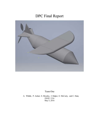
  • 1. DPC Final Report Team One A. Whittle, P. Achari, S. Moseley, J. Halper, E. McCarty, and C. Hunt, ENGE 1216 May 5, 2016
  • 2. Executive Summary: This report discusses the development and selection of a drone concept that has the intended purpose of wildlife observation, photography, and filmography. Current models on the market are expensive, heavy, and noisy, and our solution is meant to address such problems. In order to develop a successful concept for our drone, we first had to define criteria, constraints, and a use case scenario. We decided that the drone should be quiet, compact, lightweight, be capable of carrying a camera, and be able to fly above 100 ft. We chose these criteria and constraints based on an interest in ease of use for the consumer and to avoid disturbing wildlife and natural ecosystems. The drone is intended for wildlife observation, photography, and filmography by amateur and professional wildlife photographers and is designed to disturb the environment as little as possible. Our team developed two different design alternatives to choose from. The viability of each alternative was determined via decision matrices in which we weighed the importance of the following criteria: aesthetics, weight, aerodynamics, time of flight, max height, size, cost, and lift to drag ratio, and scored each alternative accordingly. We also built prototypes of the two alternatives and glide tested them from various heights under controlled conditions. We decided that the second alternative was the better option in accordance with our objectives based on the results from the decision matrices and the prototype glide test results. After choosing the better alternative, we developed a second prototype of the design. We also created a MATLAB synthesis code to model the prototype’s trajectory after launch based on assumptions about the prototype, launch mechanism, and launch environment, excluding the mass prototype, which is a user-inputted value. To test the performance of this prototype, we launched it out of a tube using pressurized water and recorded its angle of trajectory, flight distance, and maximum height of flight. We also recorded pressure of the water, the amount of water used for launch, and the wind speed at the date and time of launch. After launch testing the prototype, we found that our test results did not match our synthesis code results. This discrepancy can be attributed to the differences between the assumed values for variables in the synthesis code and reality. During this design project, our team developed designs for a wildlife photography drone. We chose which design to use based on decision matrix values and prototype glide test results and we used this design to develop a prototype for launch testing. After comparing our test results with our synthesis code results, we found that they did not match, which was a result of certain assumptions and limitations in the synthesis code. Table of Contents I. Introduction
  • 3. II. Use Case/Requirements A. Table 1 III. Ethics IV. Design Alternatives A. Figure 1 B. Figure 2 V. Design Evaluation A. Table 2 B. Table 3 C. Figure 3 VI. Prediction and Testing A. Figure 4 B. Figure 5 C. Figure 6.0 D. Figure 6.1 E. Table 4 F. Figure 7 VII. Conclusion VIII. Limitations and Future Plans IX. References X. Appendices A. Appendix A B. Appendix B C. Appendix C D. Appendix D E. Appendix E F. Appendix F G. Appendix G I. Introduction Drones are becoming increasingly popular in today’s society. They can be used to conduct many different operations, ranging from surveillance to package delivery. Each new drone that comes on the market is competing to be the best in its field, and shows improvements upon previous
  • 4. models. The drone has become progressively more technologically advanced, with an emphasis in capturing pictures and films. During this project, our design team developed a drone production concept (DPC) that would be used to photograph and film wildlife in various environments. The drone will be a low cost, high performing, and mobile competitor compared to other observer drones in the field. Two different concepts were used to decide what features to implement in the DPC design. Through prototype testing, research, and the development of a decision matrix, the second concept was determined be the option that best fit our criteria, constraints, and use case scenario. Through more testing, synthesis code development, and prototype launches, our team was able to successfully develop our DPC. Drones have a variety of different uses. For example, unmanned aircrafts that can be controlled from the ground are incredibly useful in search and rescue operations, as these machines can record events happening in dangerous situations and relay a live feed to the proper authorities, enabling them to take action. Drones can also be used to deliver packages, as surveillance machines for public or private use, or as a security measure for any member of the public. Drones can also be used in aerial photography and filmography, however there are certain drawbacks and limitations to this if one’s intention is capturing images of wildlife in nature. These shortcomings have encouraged our design team to develop and produce a drone that can capture high definition footage and photographs of wildlife from the air. II. Use Case/Requirements Our team is a small technology startup company that has designed a drone production concept with the target demographic of professional and amateur photographers/filmographers. The drone will specialize in observing wildlife located in potentially dangerous terrain or sensitive ecosystems such as forests, isolated mountains, and glaciers. Modern observer drones implement high-quality cameras and are composed of aerodynamic materials in order to ensure their success, however these products cost approximately $1400 and their average battery life is approximately 28 minutes [1]. Furthermore, drones are known to emit noises loud enough to disturb its surrounding environment. There are solutions being developed with the aim of cutting down on noise emissions, such as reducing the amount of propellers or employing several small motors instead of one large one, however this is still an issue in the drone market [2]. High cost and high noise emission are examples of features that we would like to improve upon in constructing our drone, as these design changes would allow our product to be more practical for consumers. There are several parties that could be affected by the production and success of our drone, including company employees, drone manufacturers, investors, consumers, and consumers’ clients, which may include wildlife magazines, movie producers, and advertisers. Our DPC is less than 10 inches in diameter and less than 30 inches in total length, as seen in Figure 1. These size constraints were created to ensure that the drone will be large enough to support a camera and all of its inner components, while being small enough to foster easy mobility. Although our length constraint is 30 inches, we expect the drone to be much shorter to allow for even easier mobility. Most drones that implement cameras are quadcopters as opposed to our airplane-like drone design. When being transported, quadcopters must be kept in their boxes to avoid damage, so we aimed for a design that is lightweight and compact so it can be
  • 5. easily carried. The drone’s tube-like structure and folding wings will allow it to easily fit into a bag while remaining intact. The bag can then be carried to the desired destination and the drone can be launched by gently throwing it like a model airplane. The DPC’s weight should be less than 3 pounds to also allow for easier mobility and maneuverability. The drone must be easy to carry and alleviate as much work for the user as possible. We chose a constraint of 3 pounds, as our competitor, the Phantom 4, is 3.04 pounds[1]. Although a small difference, this lighter weight will give our drone an edge over the Phantom 4 and other competitors. A lighter weight will also improve the lift upon drag ratio. Since weight is the force a gravity, as the mass increases the force of gravity on the DPC would also increase. The only force counteracting the weight is lift. This means weight and lift and directly proportional; if weight goes up, so does the lift needed to keep it in the air. [3] Table 1: Criteria and Constraints In order for our DPC to be useful to our consumers, our team had to define important flight requirements. Our drone must be able to maneuver around obstacles, such as trees and hills, in different situations, so we decided that the drone must be able to reach a height of at least 100 ft. Ideally our drone will be able to fly higher than this in order to provide more space to maneuver around tall objects, and to allow enough time to locate and record footage of surrounding wildlife. Another concern is the drone’s time of flight. As previously stated, the Phantom 4 can maintain an air time of 28 minutes. We would like our drone to maintain an airtime of at least an hour, over twice that of the Phantom 4. This extra time will give the user a longer period of uninterrupted filming. In addition to size, weight, and flight guidelines, we also considered the drone’s retail and manufacturing cost. A high quality drone for commercial use can cost over $1000, retail; the Phantom 4 costs $1400, retail. The materials chosen for our DPC cost a total $578. We determined we would use a magnesium structure similar to the Phantom 4 and an aluminum composite body to ensure a durable, lightweight product. [4][5]. Our solution includes the implementation of a GoPro, which would provide the drone with the same quality camera as that on the Phantom 4, but at a much cheaper price of $500 per camera [6]. Overall, with the inclusion of labor and design, our price point for the DPC will be $900 which is lower than our target price of $1000 as seen in Figure 1.
  • 6. Our drone requires a propulsion system to keep our it in the air and to provide extra lift. The propulsion system will be electronic and will be able to be recharged after each use. We will also develop an app based controlling system, similar to that of the Phantom 4, instead of a remote to cut down on material and manufacturing costs. The app will come free with the purchase of the DPC. III. Ethics In regards to the ethics of our drone, several issues must be addressed. The drone is meant to fly high above the land it is surveying, which brings up the issue of privacy infringement. The camera could capture feed of civilians without their knowledge while in the air, which is could be considered an invasion of privacy, but this cannot necessarily be controlled; campers and hikers are at most risk of this happening. Another possible issue arises with the idea of trespassing. These drones could potentially be used to survey and gain information on restricted properties, which is definitely not one of its intended purposes. Furthermore, studies show that the heart rates of animals such as bears and penguins spike drastically when a drone flies by overhead. "The magnitude of some of the heart-rate spikes were shocking," says Mark Ditmer, a wildlife ecologist at the University of Minnesota. “To see heart rates go from 41 beats per minute prior to the unmanned aerial vehicles' flight to over 160 beats per minute during the flight was far beyond what we expected[7]." This is not an ideal situation, as we do not want our drone to scare those which we are trying to observe. The discovery of a species in a specific area could also include ethical issues; this could lead to invasive human presence in sensitive environments, which would impede on the welfare of the affected wildlife. There is no way to avoid all of these ethical issues, however, we can work diligently to minimize their effects. IV. DesignAlternatives In order to decide how to construct our drone, we developed two design alternatives. Our first DPC, Figure 1, implements short, rectangular wings. The wings tilt downward and are connected by a thin structure that pierces the 4-inch diameter body. Both the nose and the tail converge at a point. Most of the weight is located towards the front of the bullet-shaped design. Instead of our desired teardrop wing shape, we settled for a rectangular design, which ended up being our closest option. This model lacks stabilizer fins, but does incorporate vertical tailfin. The lack of this feature, as described by Life Science, will not allow “air to move faster over the top” of the wing than the bottom of the wing[3]. Ultimately, the lack of stabilizer fins is what caused this model to fail. The vertical fin located at the back does little to stabilize our model, as the model is not heavy enough for the center of mass to be located under the center of the wings, which is necessary in a design without stabilizer. Additionally, the durability of this alternative was poor and its wings had a tendency to bend at undesirable angles.
  • 7. Figure 1: Design concept #1 Our second concept, Figure 2, incorporates distinct, more desirable features. Instead of possessing two wings that penetrate the fuselage, there is a single, large wing attached to the top of the drone. The body of the drone is connected to the tail by a narrow section and the tail is equipped with a tailfin and stabilizers. The purpose of the stabilizers is to “provide stability for the aircraft, to keep it flying straight,” and to prevent an “up-and-down, or pitching, motion of the aircraft nose” [8]. The designs’s sleek body and long wings are an improvement upon the bulky body and choppy wings of the first alternative. This model exhibited improved lift, stability, and durability compared to our first concept. Figure 2: Design concept #2 Several different materials, many household, were used in the construction of our low-fidelity DPC prototypes. Assembling the prototypes was fairly simple with some trial and error. Although the two different concepts seem similar in design, the only features that these two alternatives share are the tailfin, the propulsion system, and the camera. The camera is located at the bottom of the body and is positioned downward to help capture photographs of the wildlife at hand.
  • 8. V. DesignEvaluation After we developed two alternatives for our DPC, we evaluated each concept individually. We did this by testing the lift to drag ratio (L/D) of each alternative by glide testing each prototype from different heights in a controlled environment and recording the horizontal distance of each throw. Then the L/D ratio was then calculated using the mass of the prototype along with the throw distance. This gave us an approximation of the L/D ratio which helped us determine which alternative performed better. The results from these glide tests can be seen in Table 2 below. Table 2: Prototype Testing Results In addition to prototype glide testing, we also used decision matrices, see Table 3, to help us determine the preferred alternative for our DPC. In the first step of our concept selection, we rated our established criteria against one another. We decided that certain criteria were more important than others in our design. Our criteria, in order of decreasing importance, are: lift to drag ratio, aerodynamics, time of flight, size, weight, maximum height, cost, and aesthetic. These criteria were rated as such because it is essential that the performance of the plane is the most important factor in our design. Lift to drag ratio is essential to the performance of the plane which is why it carries the most weight in our decision matrix. Half our criteria were rated on a scale of 1 to 10 and were objective criteria. Objective criteria included: aesthetics, aerodynamics, size, and cost, and could not be quantified under the circumstances of developing the decision matrices. We did not include time of flight and max height in our concept selection because they could not be recorded in our testing exercise. The weight was rated on a scale of .001-1 pounds. This was decided because it was determined that a 1 pound concept would be ideal. Lift to drag ratio had been rated on a 1-40 ratio. This was determined because it was discovered in our research that some planes get up to 40 on there L/D ratio.
  • 9. After we scored each of our criteria on their corresponding scales, each score was normalized against the highest and lowest values of its grading scale. Then the normalized scores were weighted and added up. After adding up the weighted scores, we determined that our second design concept was the more viable option. Since design 2 was the most viable option, we decided to base out DPC off of it. As you can see in Figure 3, we kept the wings on top, and horizontal and vertical stabilizers just as concept 2 had them. Table 3- Decision Matrix Figure 3: Concept 2 DPC drawing VI. Prediction and Testing
  • 10. Before approving our DPC, it was necessary to create a higher fidelity prototype of our design. We constructed the DPC with our constraints, criteria, and use case scenario in mind. Our DPC had to be less than 3 pounds, less than 30 inches long, less than 10 inches in diameter, be able to fly higher than 100 feet, and have a flight time above an hour. The implementation of these guidelines can be seen in Figures 4 & 5 . When planning our materials, we had to ensure that the weight of our prototype was similar to our actual DPC to be able to get an idea of how well it will perform at that weight. To keep the prototype lightweight, we made the wings out of styrofoam. Though styrofoam is fairly weak alone, stacking multiple layers of styrofoam on top of eachother allowed the wings to stay study and light. We also added horizontal and vertical stabilizers which were also made out of styrofoam to keep our total mass to a minimum. We attached one AA battery to the nose and one on the bottom of the prototype to shift its overall center of mass and account for the weight of the motor. The batteries also allowed us to fix the position of the wings which, in turn, created the best lift to drag ratio. Figure 4: Top view of prototype concept #2 Figure 5: Side view of prototype concept #2 For our project we programed a synthesis code to approximate the launch of our prototype. This code had multiple equations that simulated and graphed the results of different aspects of the launch. The code calculates the vertical position, velocity, pressure, and time of flight of the prototype with a time interval of .001 seconds. Once the calculations are complete, each array of information is plotted on a graph relative to the time of flight. Lines 35, 55, 57, and 59, see Figures 6.0 and 6.1, are lines of code that store each calculation into an array; “p” is the variable for pressure, “v” for velocity, “y” for horizontal position, and “time” for time of flight. Each of the following equations use different assumptions made in the beginning to calculate each variable. Lines 7 - 20 in Figure 6.0 show what each variable stands for and the units of the variable. This code was useful in that it gave us a model of what our prototype launch might be like. Because the code is dependent on the empty mass of our prototype, we can predict a suitable empty mass for our prototype that will generate the best results within the code’s predetermined conditions. However, there are a number of limitations in the synthesis code. First, predetermined conditions such as drag, volume of water, and volume of bottle are not always constant as assumed in the synthesis code. Each bottle (plastic, 2 Liter) is shaped differently depending on the manufacturer, and therefore prevents the “VT” variable from being
  • 11. the same in all cases. The code is also written for uncommon units of measurement. The values are in units such as “slugs”, and “feet per seconds squared” put a bit of a mathematical language barrier between our code and metric users. Figure 6.0 First half of Synthesis Code
  • 12. Figure 6.1 Second half of synthesis code Using the simulation from the synthesis code we predicted our prototype would reach a height of about 100 ft with 300 mL, see Figure 7. After testing, we measured the actual launch height to be about 42 for the 300ml launch. A few reasons why our test results did not match our prediction from the synthesis code is because of variables such as wind, drag, and the structure of our prototype. Within our code there was no wind variable to accommodate for. Therefore, the wind during our launch, which was calm [9], could have affected the distance, height, and direction our prototype traveled. The drag ratio in the synthesis code, as previously mentioned, only accommodates for the body of the prototype. Though the body of the prototype heavily affects drag variable, the wings, horizontal and vertical stabilizers, and nose of the prototype also account for the drag value. Because of these additions, the drag value for our prototype was larger than the drag value generated by the synthesis code. Another reason for the discrepancies between our prediction and our results was structure of our prototype. The wings on our prototype were not structurally stable, so when the prototype was launched, the wings were knocked out of place. The synthesis code could have been modified to produce more realistic predictions of our launch if we calculated the drag caused by the wings and included a wind variable. Optimal test conditions would have clear weather with no wind with perfect launch execution. If there was zero wind, our wings were structurally sound, and we accommodated for the drag caused by our additions to the body of our prototype, then we could have have, theoretically, achieved a perfect launch resulting in the same results as predicted. Table 4: Launch data of prototype Table 4- Launch
  • 13. Data Launch Ml of Water Appx. Simulated Altitude (ft.) Actual Altitude (ft.) Horizontal Distance (ft.) 1 200 87 18.75 22 2 300 97 40.5 69 3 300 97 45 43 Average 93.66 34.75 44.67 Figure 7. Graph of Predicted Altitude versus Time VII. Conclusion Our goal for this design project was to develop a drone product concept that would take high quality, aerial footage of wildlife and natural environments. Our drones would be smaller, cheaper, and more versatile than the drones that are currently on the market. Initially we developed two concepts, one that has square wing design without stabilizers and another that has a larger, sturdier design with stabilizers. After testing the concepts we decided, with the help of a decision matrix, that the sturdier, larger wingspan design would fly better than its competing design. After selection a concept, the design of that concept was translated into a prototype. This prototype was then tested and it reached average horizontal distance of 45 feet from the launch site. Overall, the initial selection of our concept and the building of our prototype leads us to believe that our final product will fly with great performance and credibility. VIII. Limitations and Future Plans Our design strategy was limited in a few key ways. Our synthesis code projected our flight height to be about 100 ft. In reality, this value was only about 34 ft. Our code was inaccurate in
  • 14. predicting the launch data. This code was inaccurate primarily due to the drag coefficient in the code. This value was set at .0007 and in reality was probably a lot higher. Another limitation of our code was several uncontrolled variables during the launch. These variables include wind speed and the weak structure of the prototype. This had a substantial impact on the performance of the prototype. In future testing it might be best to incorporate air resistance into the synthesis code. This would give us a better prediction on the performance of the launch. We might also choose to build our prototype out of different materials besides plastic bottles and foam board. This would ensure that the prototype has a strong structure, durable enough for multiple, successful launches. We could also alter the angle of launch in future tests. This could give us a greater distance on the launch.
  • 15. XI. References [1] "DJI Phantom 4", PCMAG, 2016. [Online]. Available: http://www.pcmag.com/review/342895/dji-phantom-4. [Accessed: 30- Apr- 2016]. [2] D. Hambling, "Silence of the drones: How to quiet that annoying aerial buzz", New Scientist, 2016. [Online]. Available: https://www.newscientist.com/article/dn27696-silence-of-the-drones- how-to-quiet-that-annoying-aerial-buzz/. [Accessed: 05- May- 2016]. [3] “The Physics of Flight,” Flight. [Online]. Available at: http://www.lcse.umn.edu/~bruff/bernoulli.html. [Accessed: 05-May-2016]. [4] "Magnesium Metal Ingot, 99.95% Pure, 8 Ounces: Amazon.com: Industrial & Scientific", Amazon.com, 2016. [Online]. Available: http://www.amazon.com/Magnesium-Metal-Ingot-99- 95-Ounces/dp/B005DPFJJO. [Accessed: 24- Apr- 2016]. [5] A. Gameros, "The Use of Composite Materials in Unmanned Aerial Vehicles (UAVs)", Azom.com, 2016. [Online]. Available: http://www.azom.com/article.aspx?ArticleID=12234. [Accessed: 24- Apr- 2016]. [6] H. Black, "GoPro Karma", Shop.gopro.com, 2016. [Online]. Available: http://shop.gopro.com/hero4/hero4-black/CHDHX-401.html. [Accessed: 30- Apr- 2016]. [7] Charles Q. Choi, “Drones Spook Bears”, Life Science, 2014. [Online]. Available:http://www.livescience.com/51846-drones-spook-bears.html/ [Accessed: 24-Apr- 2016]. [8] N. Hall, Ed., “Horizontal Stabilizer - Elevator,” Horizontal Stabilizer - Elevator, 05-May- 2015. [Online]. Available: https://www.grc.nasa.gov/www/k-12/airplane/elv.html. [Accessed: 04-May-2016]. [9] “Weather History for KBCB - April, 2016,” Weather History for Blacksburg, VA, 13-Apr-2016. [Online]. Available at: https://www.wunderground.com/history/airport/kbcb/2016/4/13/dailyhistory.html?req_city=blac ksburg. [Accessed: 04-May-2016]. X. Appendices Appendix A
  • 16. Evaluation of Sources: [1] Strong. This website dedicates its content to describing the product that is it selling, the Phantom 4 drone, so the information stated contributes to an accurate representation of the product itself. [2] Medium to Strong. New Scientist is a magazine dedicated to providing accurate scientific and technological information. The author of this article, David Hambling, is a credible journalist who has been writing science articles for different magazines for years. [3] Strong. This is a credible source as it comes straight from the University of Minnesota. [4]Strong. This page is dedicated to selling magnesium, so the price must be exact. [5]Medium to Strong. The author is an aerospace engineer, which gives him credibility over the subject of aerospace, however the website does not provide any outside information regarding publication, copyright, etc. [6] Strong. This page is dedicated to selling its product, the GoPro, so the information it has on this device must be accurate. [7] Medium to Strong. Life Science is a reputable source, however not an official educational science site. The author has a masters degree in journalism and typically covers many science related articles for Life Science. [8] Strong. This page does an exceptional job explaining what a horizontal stabilizer is and is credible because it stems from a .gov site. [9] Medium to Strong. This page is dedicated to displaying weather and all other aspects related to weather, however it does not include any important outside information. Appendix B Table A. Invoice for Billable Hours Week Number 3 4 5 6 7 8 9 10 11 12 13 Total Hours per Person Task Team Roles & Team Charter Needs Assessment Report, Project Schedule Begin Research Contin ue Resear ch Spring Break Trajecto ry Module , Begin Modeli ng Model Design Finish Modeling, Prepare Design Status Review DPC Four Square, Synthesis Test Shape Design Prototype, Initial Concept Selection Launch Prototype, Final Presentation Preeya 0.5 1.5 1 1 0 0.5 0.5 4 2 4 6 21 Justin 0.5 1.5 1 1 0 0.5 0.5 2 2 4 6 19 Christian 0.5 2.5 1 1 0 0.5 0.5 4 3 4 6 23 Ethan 0.5 1.5 1 1 0 0.5 0.5 4 2 4 6 21 Alli 0.5 1.5 1 1 0 0.5 0.5 4 3 4 6 22
  • 17. Saede 0.5 1.5 1 1 0 0.5 0.5 2 1 4 6 18 Grand Total Hours 124 Total Amount ($125 person/hour $15,500 Appendix C Drawings: Concept #1 This concept includes square, downward-slanted wings that run through the fuselage. It also contains a tailfin and a camera, which is positioned on the bottom of the body. Concept #2
  • 18. This concept has one large wing that is located on top of the body. It not only includes a tailfin and a camera, but also a horizontal stabilizer. Appendix D Synthesis Code Program: 1. %4M Group 1 2. %This code calculates the pressure, velocity, and vertical position 3. %with in the bottle rocket as time moves on 4. clear 5. clc 6. 7. y0 = 0.0; % Initial altitude, ft 8. VT = 0.07063; % Total volume of bottle,2 Liters, expressed in cubic ft 9. VW = 0.01059; % Volume of water, 300 ml, expressed in cubic ft (this is the recommended maximum volume of water to put in a 2 L bottle) 10. v0 = VT-VW; % Initial volume of air in cubic ft in a 2 liter bottle. A 2 liter bottle contains 0.07063 cubic feet. The max water volume to put in a 2 L rocket is 0.01059 cubic ft or 300 ml. The air volume for that amount of water is 0.06004 ft^3 11. D = 0.000073; % Rocket drag: 0.5*Cd*x-sectArea *rho. Assume this value of drag coefficient Cd=.7, rho=.0024sl/ft^3, and a 2 L bottle has 4 in diameter. mr = .00367; % Empty Mass of the rocket in slugs (53.61 grams) 12. g = 32.2; % Acceleration due to gravity (ft/s^2) 13. P0 = 11520.0;% psf initial bottle air pressure(80 psi) 14. Ae = 0.004;%exit area, sq ft, of a 2 liter bottle 15. Pa = 2116.8;%ambient air pressure psf (14.7 psi) 16. Rho_w = 1.939;%water density in slugs/ft^3 17. mr = input('Enter the empty mass value:'); 18. tspan = 5; 19. dt = 0.001; %time intervals 20. npoints = round(tspan/dt); 21.
  • 19. 22. p = zeros(npoints,1); 23. time = zeros(npoints,1); 24. v = zeros(npoints,1); 25. y = zeros(npoints,1); 26. 27. % the initial conditions 28. p(1) = P0; 29. v(1)= v0; 30. y(1)=y0; 31. time(1) = 0.0; 32. 33. for step=1:npoints-1 % loop over the timesteps 34. p(step+1) = p(step) - ((p(step).^2)/(P0*v0))*Ae*(sqrt(2*(p(step)- Pa)/Rho_w))*dt; %calculates pressure 35. 36. %Prevent rocket pressure from going below atmospheric pressure 37. if p(step+1) < Pa 38. p(step+1) = Pa; 39. end 40. 41. %compute new mass 42. if p(step+1) > Pa 43. Mass = Rho_w*(VT-(P0*v0/p(step))+mr); 44. else 45. Mass = mr; 46. end 47. 48. %Prevent mass from going below the empty rocket mass 49. if Mass < mr 50. Mass = mr; 51. p(step) = Pa; 52. end 53. 54. v(step+1) = v(step) + ((((2*Ae*(p(step)-Pa))- (D*v(step)*abs(v(step))))/Mass)-g)*dt; %calculates velocity 55. 56. y(step+1) = y(step) + (v(step)*dt); %calculaes vertical position 57. 58. time(step+1) = time(step) + dt; 59. 60. %Prevent altitude from going below 0 61. if y(step+1) < 0 62. v(step+1) = 0; 63. y(step+1) = 0; 64. end 65.
  • 20. 66. end 67. 68. plot(time,p); 69. xlabel('time(sec)') 70. ylabel('pressure (psf)') 71. title('Pressure Variation Over Time') 72. figure 73. plot(time,v); 74. xlabel('time(sec)') 75. ylabel('velocity (ft/sec)') 76. title('Velocity Variation Over Time') 77. figure 78. plot(time,y); 79. xlabel('time(sec)') 80. ylabel('Altitude (ft)') 81. title('Altitude Variation Over Time') Appendix E Project Schedule:
  • 21. Appendix F Requirements / Use Scenario: Appendix G
  • 22. Figure 4: Side view of prototype concept #2 Figure 5: Top view of prototype concept #2 As seen in Figures 4 & 5, the wings of the model were created using 3 different layers of styrofoam. They were glued and taped into place to ensure stability and to increase the aerodynamics of the prototype. As shown at the bottom of Figure 4, a few platforms were placed on the bottom of the prototype; these represent the camera that will be placed in the relative area on our actual product. The AA battery shown on the left side of Figure 4 represents the electric engine that will go inside our drone to power the propeller.