1. Heat recovery, Emulsion Trim Cooler and Emulsion cooler outlet
temperature control
I am not sure this project has proceeded heat integration with Pinch technology or not, but It seems that
there is big room for raising the level of heat recovery. I have two questions about current heat
exchange flow scheme as below:
1. The outlet temperature of Emulsion/BFW exchanger is set at the required FWKO inlet temperature
and no heat duty for trim cooler normally in simulation. The adjustment of inlet temperature of
FWKO in operation can be executed in this way:
• If the outlet temperature is lower than required operating temperature of FWKO, then part
of BFW will need to bypass the exchangers. It will result in lower BFW final temperature and
heat recovery level.
• If the outlet temperature is higher than required operating temperature of FWKO, then the
control valve for cooling glycol to Trim Cooler will need to be opened to cool emulsion down
with Trim Cooler. As the Trim Cooler is designed for upset conditions and has quite big
design flow (215 m3
/hr), any small glycol flow could easily fall into the dead band of glycol
control valve, this make accurate control of FWKO inlet temperature impossible.
2. The outlet temperature of Produced Gas /BFW exchanger is 151°C for Light Gas Condensate case
and 157°C for Heavy Gas Condensate case (see attached PDF file) and the latent heat contained in
PG could be further recovered by BFW
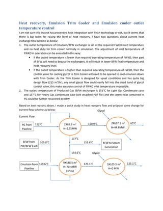
Based on two reasons above, I made a quick study in heat recovery flow and propose some change for
current flow scheme as below:
Current Flow
BFW from
PW/BFW Exch
PG from
Pipeline
2X65.9 m2
H=2.75MW
2X657.1 m2
H=44.8MW
105.8°C
152°C 150.9°C 65°C
Glycol
153.6°C
137°C
BFW to Steam
Generation
9X548.5 m2
H=70.4MW
(3P3S)
Emulsion from
Pipeline
169.6°C 3X105.5 m2
H=0 MW
154.6°C
125.1°C 125.1°C
Glycol
2. Compared to current flow, proposed flow has some advantages list below:
1. The final BFW outlet temperature is 156.6°C, 3°C higher than current design without any heat
transfer increase (6699 m2
for current design vs. 6645.6 m2
for proposal). This means 5.3 MW
more heat gain in BFW heat recovery and same amount less glycol cooling duty, which account
for 5.9% of BFW heat recovery.
2. This solves FWKO feed temperature unsteady control problem.
3. It eliminates the requirement for two control valves (one flow rate adjustment for BFW through
Emulsion/BFW exchangers and one bypass flow control) and maximizes the heat recovery.
In current design, 40°C cooling glycol is used as Trim Cooler cooling medium to cool emulsion above
120°C. The potential problem with it is the low wall temperature on the tubes of Trim Cooler and it will
cause emulsion density to layer and promote rag layer buildup in FWKO. I am thinking to add a medium
level cooling glycol, say glycol at 75°C or 80°C, to be used as emulsion and PW Coolers. Thus, the wall
temperature can be raised and rag layer build-up problem can be relieved to some extent. More
importantly, some hot cooling glycol in lower temperature can directly be used as cooling medium,
rather than being sent to air cooler cooled to 40°C. The advantage for this is that it reduces the cooling
duty of air cooler on one hand. On other hand, it raise the hot cooling glycol return temperature and this
hot cooling glycol either can be used as heating glycol or be cooled in air cooler with bigger heat transfer
temperature difference, so that the air cooler area can be reduced further.
Moreover, I found there is no direct temperature control to FWKO feed, the operating temperature of
FWKO is adjusted and controlled by TIC-0141 (which measures wet emulsion temperature in FWKO
outlet, then adjusting BFW bypass flow or cooling glycol flow). As it is known, FWKO has very big
capacity and the retention time of wet emulsion in FWKO is about 30 minutes. Any high temperature
PG from
Pipeline
3X505.2 m2
H=37.5MW
152°C 120.8°C 65°C
105.8°C
169.6°C
130.2°C
156.6°C
144°C 125.1°C
3X203.7 m2
H=10.1MW
6X623.4 m2
H=40.9MW
(3P2S)
3X259.5 m2
H=29.4 MW
BFW from
PW/BFW Exch
Emulsion from
Pipeline
BFW to Steam
Generation
3. and low temperature will not be detected by TIT-0141 and TIT-0143 immediately (30 minutes delay for
complete detection though they can measure diluted temperature some time later). This control is not
sensitive and accurate for operating temperature control in FWKO). As my understanding, though the
operating temperature in Treaters is important, it does not mean the temperature in FWKO can be
ignored. On the contrary, the gravity separation is more sensitive to temperature change and
temperature control is more important in FWKO than in Treaters. On the other hand, if the temperature
in FWKO is well controlled, then the temperature in Treaters will be more steadily controlled as the
amount of diluent added to FWKO and Treaters are comparatively fixed.
This is my preliminary consideration, I am not sure it is reasonable and feasible or not.
Which is better, One FWKO or more?
One FWKO is used in current design, it may save some investment, but it may not be better considering
the turndown ratio, potential Rag layer problem and emulsion flow in pipeline during steaming and early
production. As literature shown, typically 3:1 to 4:1 turndown is still the practical limit on heavy oil
equipment turndown, cooling and low flow zones will cause emulsion density layering and interface rag
layer builder-up, so the bigger FWKO is not always better. Another issue with one bigger FWKO is sand
collection in low point of pipeline which will be brought out with low flow during steaming and early
production as emulsion flow is required above a critical flow so that sand carried with emulsion could
not be settled down. The bigger design flow, the more serious sand settles down during low flow.
Heating glycol return from Combustion Air Heater
Based on simulation, the heating glycol return temperature is 25°C in winter (the temperature would be
around 40°C in summer based on 15°C approach temperature). This way, is it necessary to mix this part
heating glycol return with cooling glycol and heating glycol from other sources to pull inlet temperature
of air cooler and LMTD down? Why not it is used directly as cooling medium?
PSV relieve destination and Flare Header sizing
In this project, it seems all PSV outlets are connected to flares. As other project did, relieves from some
PSVs were not connected to HP Flare, like water or steam relief, it can be relieved to safety place near
equipment and then liquid can be collected in sump and vapour is vent to air without any harm to
environment. I am not sure if there is any regulation to rule out these kinds relieves.
Another issue regarding flare system is the size of HP Knock-out Drum. The governing case for HP flare
header and HP Flare Knockout sizing is wet emulsion relief from FWKO when PW outlet in FWKO is
blocked out, thus a 24” header and a huge HP Flare Knockout Drum (15’ID x 80’ S/S, very close to size of
FWKO) are designed to handle the relief for the case. A CHD Vessel at same size is designed as spare HP
Flare Knock-out Drum. As FWKO has two equal size PSVs, one with lower set pressure designed for fire
case relief and outlet block-out case and another with higher set pressure designed for outlet block-out
case only. Two PSVs share the total relief load of governing case. In current design, both PSVs are
relieved to HP Flare Knockout Drum and HP Flare Knock-out Drum is designed to store relief liquid for
governing case. I have been exploring the possibility to connect the PSV for both fire case and liquid
relief case to HP Flare Knock-out Drum and connect to another PSV to CHD Vessel, let two vessels share
4. the total liquid load to reduce the sizes of both HP Flare Knock-out Drum and CHD Vessel. I am not sure
whether this is practical and feasible or not.