RLS type indoor SF6 load break switch(Disconnector)
•
1 j'aime•590 vues

Indoor SF6 Gas Load break switch, disconnector, from 11kV up to 36kV.

Recommandé
Contenu connexe
Tendances
Tendances (20)
Similaire à RLS type indoor SF6 load break switch(Disconnector)
Similaire à RLS type indoor SF6 load break switch(Disconnector) (20)
Dernier
Dernier (20)
RLS type indoor SF6 load break switch(Disconnector)
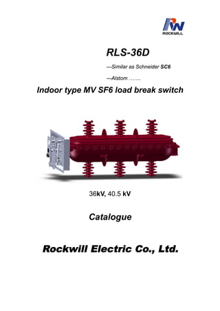
- 1. RLS-36D ---Similar as Schneider SC6 ---Alstom ……. Indoor type MV SF6 load break switch 36kV, 40.5 kV Catalogue Rockwill Electric Co., Ltd.
- 2. ++++General RLS-36 an indoor high-voltage SF6 load switch, an switchgear with the rated voltage of 36kV/40.5kV, adopted with SF6 gas as an arc-extinguishing and insulation medium, including the three contactors for switching-on and switching-off and to-ground, and is characteristic in its small volume, its convenient installation and operation and its the great adaptability with surroundings. RLS-36 of an indoor high-voltage SF6 load switch and RLS-36 of SF6 load switch plus fuse combination can function to protect and control the electric equipments for power supply and transformer substations especially being suitable for ring net cabinet, cable branch cabinet and distribution switching substation. RLS-36 of an indoor high-voltage SF6 load switch and RLS-36 load switch plus fuse combination are complied with the standards of GB3804-1990, IEC60256-1,1997, GB16926, IEC60420 etc.. ++++Service environment a) Air temperature Maximum temperature: +40℃; Minimum temperature:-5℃ b) Humidity Monthly average humidity 95%; Daily average humidity 90% . c) Altitude above sea level Maximum installation altitude: 2500m d) Ambient air not apparently polluted by corrosive and flammable gas, vapor etc. e) No frequent violent shake ++++ Main technical specifications No Item Unit Parameter 1 Rated voltage kV 36 2 Rated frequency Hz 50/60 3 Rated current A 630 wet kV 954 1min Power frequency withstand voltage dry kV 110 5 Lightning impulse withstand voltage kV 185/215 6 Rated short circuit breaking current (peak) kA 50 7 Rated active load and close circuit breaking current A 50 8 Rated transferring current A 1000 9 Rated short circuit making current (peak) kA 50 10 Rated cable(line) charging breaking current A 50 and 10 11 Cable charge breaking current in earthing fault A 20 12 Rated withstand current (peak) kA 50 13 Short time withstand current (2s) kA 20 14 Mechanism life times 2000 Note: For short circuit breaking and peak current is based on Fuse plus combination.
- 3. ++++Outline dimension & installation sizes Matching dimension of SF6 load break switch-fuse combination Fig 1) SF6 load break switch without upper cubicle Dimenssion view of load break switch Fig 2) Whole Load break switch outline ++++Primary circuit loop of load break switch Primary loop of FLN36-36 indoor load break switch and its combination is sealed in a epikote casted insulate unit by APG technology, this insulate unit has features of good insulating property, dust and dirts proof, insulate unit contains upper and lower insulate covers, inside charged 1.5bars pressure SF6 gas, the partial siding of lower cover is very thin, it's a protective measure and will burst out in the malfunction, the over pressed gas is released to protect the equipment.
- 4. ***SF6 load break switch and its fuse combination has open,close and earth three working position. a) Closed Position b) Open Position c) Earthing Position Fig 1) Working position schematic ++++Arc extinction RLS-36 load break switch adopts SF6 gas as the medium of arc extinction, when switch on and off, arc occurs and will spin under the magnetic field effect ion by the permanent magnet, cooled by the SF6 gas and extricated finally. This indoor SF6 load break switch and its fuse combination works with spring type operating mechanisms A and K,FLN36-36 load break switch equipped with the K spring operating mechanism is applied as the incoming control unit, while that equipped with A mechanism is applied as the outgoing protective unit and transformer unit. 1) "K" Type Spring Operating Mechanism Working principle of K type spring operating mechanism is spring press and release( see fig 1. it's in off position) A) Earthing operation Driven by the handle, upper crank arm 4 rotates and presses spring 2 to store energy, when the max energy reached continue rotate the crank arm, the energy storage spring starts to release energy and drive the upper trigger, enables the connecting bar to drive the crank arm, crank arm rotates and drives the moving contactor for earthing. B) Switch on operation Driven by the handle, lower crank arm 1 rotates, presses spring 2 to store energy, when the energy released, it drives the trigger 8,enables connecting bar to drive the crank arm, crank arm rotates and drives the moving contactor and load break switch turns on. C) Switch off operation Rotate the main shaft crank arm counterclockwise by the handle, release the energy storage spring and the load break switch turns off. 2) "A" Type Spring Mechanism Working principle of A type mechanism is same as K type, in addition, it has fuse striker unbuckle function. For A type mechanism, electromagnetic unbuckle is also available on customers requirement.(see fig 2) A) Switch on operation
- 5. Driven by the handle, lower crank arm 1 rotates to presse switch on spring 12 and switch off spring 8 at the same time, to provide sufficient energy required by switching off. when the lower crank arm 1 buckles the pin and drives trigger to move, it makes the lower roller wheel unbuckled, and release the switch on spring and load break switch turns on. B) Switch off operation Press the switch off button or push the unbuckle pin 2 by the fuse striker, release the spring and load switch turns off. C) Earthing operation Earthing operation of A type mechanism is same as that of K type. 3) K type and A type operating mechanism can be operated manually or motorized on request. ***Notice: only when the load break turns off, can turning on and earthing operation be done. 1-lower crank arm 2-energy storage spring 3-guider bar 4-upper crank arm 5-upper trigger 6-pull spring 7-main shaft crank arm 8-lower trigger Fig 1: K type spring operating mechanism 1-lower crankshaft 2-unbuckle pin 3-cam 4-lower roller wheel 5-upper roller wheel 6-upper crankshaft 7-upper guider bar 8-switch off spring 9-energy storage crank arm 10-main shaft crank arm 11-lower guider bar Fig 2: A type mechanism ( switch on position) 12-switch on spring
- 6. ++++Operating Mechanism & Interlock ****Mechanism interlock RLS-36 indoor type medium voltage SF6 load break switch and its fuse combination has below interlocks: A) When load break switch turns on, earthing operation can't be done B) When earthing switch turns on, load break switch turns on/off operation can't be done C) Interlock outlet of mishandling pretension is equipped Mechanism interlock diagram
- 7. ++++Installation, Maintenance & Service. ****Installation, Adjustment RLS-36 type load break switch has been strictly tested before outgoing from the factory, and fully meet the technical standards, must carefully read the installation manual and prepare as below before the installation and adjustment. Check the external appearance, any damage product is not allowed to use. Clean the equipment and get rid of the dust and dirt may caused by the transportation or other causes. After installation, be sure the load break switch is turned off, insert the handle to the earthing operating hole in the up part of operating panel, rotate the handle clockwise in 180o to earth the switch, rotate counterclockwise in 180o to switch off the earth. For switching on, turns off the load break switch firstly, insert the handle to the load break switch operating hole in the lower part of panel and turn on the load switch. From the switch on to switch off, for K type mechanism, insert the handle to the load switch operating hole and rotate it in 180 o to switch off; for A type mechanism, press the "switch off" button to switch off the load break switch, observe from the winder to confirm it, check whether the on/off indication plate works properly. Notice: only when the load break turns off, can turning on and earthing operation be done ! ++++Maintenance & Service On condition of installing in environment as this manual required and normal operations, product guaranteed to be fault free for 10 years and has a running life of 25 years, but regular check per 6 months is required. Keep the external appearance away from dust ,dirt and damp. Lubricate and operate the mechanism for 3-5 times, check whether it acts properly. Check with the pressure meter regularly, in case of meter data lower than 0.01MPa, should reload gas. When the malfunction happens in the load break switch and fuse combination, and one of the three phase immediately, gas charging should be done by professional personnel from or trained by the manufacturer. uses burns out, all three fuses should be replaced at one time, must earth the switch before the replacement. ++++Matters need attention It is NOT allowed to disassembly the self-sealed valve in front of switch( connecting end of meter). It is NOT allowed to unload the seal screws on switch at any time.
- 8. ++++Ordering Instructions ****Ordering instructions: 1. Belowing terms should be marked while ordering: Model number, product name and quantity. Model of operating mechanism ( A,K ). Provide the rated voltage specification if motorization operating is required. For load break switch + fuse combination, fuse model and specification is required. Other special requirements. 2. Documents with product from manufacturer: Certificate of qualification. Testing report for products. Packing list. Other technical documents. Notice: All technical specification same as SC6. Except the installation sizes. Tel: 0086-577-27869966, 27869968, 27869969 Fax: 0086-577-27869967 Add: No 1,Fazhan Road, Wengyang Industrial Zone,Yueqing,Zhejiang, 325604 E-mail:rockwill.sale@gmail.com(Sales) rockwill.tech@gmail.com(Technic)