SlideShare une entreprise Scribd logo
1  sur  24
GEARLESS TRANSMISSION SYSTEM SEMINAR REPORT 2016
1
Chapter 1
1. INTRODUCTION
1.1 Gearless transmission System Working principle:-
Here is a wonderful mechanism that carries force through a 90ºbend.Translating rotational
motion around an axis usually involves gears, which can quickly become complicated,
inflexible and clumsy-looking, often ugly. So, instead of using gears, this technology
elegantly converts rotational motion using a set of cylindrical bars, bent to 90º, in a clever,
simple and smooth process that translates strong rotational force even in restricted spaces .A
gearless transmission is provided for transmitting rotational velocity from an input connected to
three bent links. Both the input shaft and the housing have rotational axes. The rotational axis of the
input shaft is disposed at an angle of 90 degree with respect to the rotational axis of the
housing. As a result, rotation of the input shaft results in a processional motion of the axis of
the bent link. The rotary and reciprocating motion of bent link transmit rotation of prime
mover to 90 degree without any gear system to an output shaft without gears .The transmission includes
an input shaft.
Fig.1
GEARLESS TRANSMISSION SYSTEM SEMINAR REPORT 2016
2
CONCEPT DRAWING OF MACHINE
Fig. 2
GEARLESS TRANSMISSION SYSTEM SEMINAR REPORT 2016
3
1.2 WORKING
The Gearless transmission or El-bow mechanism is a device for transmitting motion at any
fixed angle between the driving and driven shaft. The synthesis of this mechanism would
reveal that it comprises of a number of pins would be between 3 to 8 the more the pins the smoother
the operation. These pins slide inside hollow cylinders thus formatting a sliding pair. Our
mechanism has 3 such sliding pairs. These cylinders are placed in a Hollow pipe and are
fastened at 120* to each other. This whole assembly is mounted on brackets wooden table.
Power is supplied by an electric motor. The working of the mechanism is understood by the
diagram. An unused form of transmission of power on shaft located at an angle. Motion is
transmitted from driving to the driven shaft through the roads which are bent to conform to
the angles between the shafts. These roads are located at in the holes equally spaced around a
circle and they are free to slide in & out as the shaft revolves. This type of drive is especially
suitable where quite operation at high speed is essential but only recommended for high duty.
The operation of this transmission will be apparent by the action of one rod. During a
revolution. If we assume that driving shaft “A” is revolving as indicated by arrow the driven
shaft B will rotate counter clockwise. As shaft A turns through half revolution C shown in the
inner and most effective driving position slides out of both shafts A & B The first half
revolution and rod “C” then will be at the top then during he remaining half this rod “C” slide
in wards until it again reaches to inner most position shown in Fig. in the meanwhile the other
roads have of course passed through the same cycle of movements all rods are successively
sliding inwards and outwards.
Although this transmission is an old one many mechanics are skeptical about its operation,
however it is not only practicable but has proved satisfactory for various applications when
the drive is for shafts which are permanently located at given angle. Although this illustration
shows a right angle transmission this drive can be applied also to shafts located at
intermediate angle between 0* and 90*.In making this transmission, it is essential to have the holes for a
given rod located accurately in the same holes must be equally spaced in radial and
circumferential directions, be parallel to each rod should be bent to at angle at which the shaft
are to be located. If the holes drilled in the ends of the shafts have “blind” or closed ends,
there ought to be a small vent at the bottom of each rod hole for the escape of air compressed
by the pumping action of the rods.
GEARLESS TRANSMISSION SYSTEM SEMINAR REPORT 2016
4
1.3 APPLICATION
The featured product has its widest application as an extension for a socket wrench. Here the
design makes it easy to reach fasteners in the automotive and other mechanical industries, where direct
access to bolts and screws is often limited. However, the possible applications for this
technology extend into numerous fields. Just think of the possibilities for power transmission
in push bikes, toysand hand-cranked equipment, or for movement transmission in store and
outdoor signage.
1. Driving for all kinds four faced tower clocks. The elbow mechanism was first use in
the year 1685 for the famous London tower clock named bigben.
2. The mechanism is invariable used for multiple spindle drilling operation called the
gang drilling.
3. Used for angular drilling between 0 to 90 degree position.
4. Lubrication pump for C.N.C. lathe machines.
5. The mechanism is very useful for a reaching a drive at a clumsy location.
6. Air blower for electronic and computer machine.
7. The mechanism has found a very usefully use in electronic and computer technology
for multiple.
8. The elbow mechanism is used for movement of periscope in submarines,
9. The year 1685 for the famous London tower clock.
GEARLESS TRANSMISSION SYSTEM SEMINAR REPORT 2016
5
Chapter 2
COMPARISON
2.1 COMPARISON OF GEARED DRIVE WITH GEARLESS DRIVE
The gearless drive is capable of transmitting motion at any fixed angle between 0* to 90*.
The desired effect is also possible with help of bevel gearless differ to a great extent not only
in their manufacturing method or working principle but also in other aspects etc. the aspects
have been discussed below.
I) MANUFACTURING METHODS:-
Bevel gears, which are straight teeth or spiral teeth are manufactured on special purposes
machines like Gearless machines. These required large amount of calculation and every pair
or set of gear are made together and there is no interchangeability. The gearless drive has this
advantage that it can be machined and manufactured on conventional machines it provide complete
freedom of interchangeability.
II) WORKING PRINCIPLE:-
A gear comprises of a frustum of a cone with teeth out on its periphery. The driving gear mounted on the input
shaft meshes with the driven gearand thus provides motion at right angle to the input shaft .The working of
the gearless drive has been explained in the earlier chapter and it obviously very different from the
above.
III) CAUSE OF FAILURE:-
Starting with the principle that failure Id the result of the stress i.e. condition more severe than the
material can with stand. The various type of failures such as pitting, corrosion, erosion, fatigue etc.
Cause the wearing of the gear tooth resulting in the tooth leads to the replacement of the entire
gear set, which is very expensive. The effect of pitting, erosion, corrosion etc. will be present in the
gearless drive also but the effect of these will be not be as severe as in the case of
geareddrive, failure will take place in the piston e.g. Either bending or crack Of the pins, but
the main advantage is that only particular pin will have to be replaced instead of case of
failure.
GEARLESS TRANSMISSION SYSTEM SEMINAR REPORT 2016
6
IV) MATERIAL:-
The material chosen for any component must
(a) Be easily available.
(b) Be capable of being processed in the desired examinations and have the necessary
physical properties. The gears generally fail due to bending, fatigue and impact and
the gears are also responsible for the failure of the components in the gears have to
very carefully determine since it may lead to pitting.
V) LUBRICATION AND COOLING:-
A few open gears drives are lubricated by grease but gear units are usually totally enclosed and oil
lubricated. The arrangement for lubrication is simple and easy, since it requires only a leak
proof housing in which the gears are placed and oil is filled. This lubricating also acts as cooling medium.
The heat generated and it then spreads to otherareas. In the gearless drive lubrication and cooling
plays a very major role. The efficiency of the mechanism is affected by lubrication. Although
the system of lubrication and cooling complex as discussed in the next chapter but gives good
result. Due to sliding contract, between pins and cylinders, heat generated is more and thus
effective cooling is amust.
VI) TORQUE TRANSMITTUNG CAPACITY:-
The gear drive is capable of transmitting very high torque ascompared to the gearless drive which is ment only
for low torque applications.
GEARLESS TRANSMISSION SYSTEM SEMINAR REPORT 2016
7
VII) LIFE AND EFFICIENCY:-
Designed life represents the total period of operation, regardless of any variations of torque or
speed, which may occur during that the time industrial. The geared drive is capable of giving
an efficiency of about 40% and certain errors like backlash, hunting etc. cannot be
eliminated.
VIII) Comparison of this drive with gear drive infinite no of speed can be
available which cannot toeasily possible in gearbox.
IX) Optimum machining is important which require exact machining speed for particular
operation which is very difficult to gain for gear drive but can easily available by this drives
increase the following.
1)Tool life
2) Productively
3) Energy saving.
X) The different speed at eight angle ( 0 to 90) is possible which is not easily possible in gear
drive.
XI) Efficiency can be increased by increasing no of pins, by precise machining, selecting
suitable material and proper lubrication.
GEARLESS TRANSMISSION SYSTEM SEMINAR REPORT 2016
8
Chapter 3
3.1 SELECTION OF MATERIAL
The proper selection of material for the different part of a machine is the main objective in the
fabrication of machine. For a design engineer it is must that he be familiar with the effect, which the
manufacturing process and heat treatment have on the properties of materials. The Choice of
material for engineering purposes depends upon the following factors:
1. Availability of the materials.
2. Suitability of materials for the working condition in service.
3. The cost of materials.
4. Physical and chemical properties of material.
5. Mechanical properties of material.
The mechanical properties of the metals are those, which are associated with the ability of the
material to resist mechanical forces and load. We shall now discuss these properties as
follows:
1. Strength : It is the ability of a material to resist the externally applied forces
2. Stress: Without breaking or yielding. The internal resistance offered by apart to an
externally applied force is called stress.
3. Stiffness: It is the ability of material to resist deformation under stresses. The
Modules of elasticity of the measure of stiffness.
GEARLESS TRANSMISSION SYSTEM SEMINAR REPORT 2016
9
4. Elasticity: It is the property of a material to regain its original shape after deformation
when the external forces are removed. This property is desirable for material used in tools
and machines. It may be noted that steel is more elastic than rubber.
5. Plasticity: It is the property of a material, which retain the deformation produced under
load permanently. This property of material is necessary for forging, in stamping images on coins
and in ornamental work.
6. Ductility: It is the property of a material enabling it to be drawn into wire with the
application of a tensile force. A ductile material must be both strong and plastic. The ductility
is usually measured by the terms, percentage elongation and percent reduction in area. The
ductile materials commonly used in engineering practice are mild steel, copper, aluminium ,
nickel, zinc, tin and lead.
7. Brittleness: It is the property of material opposite to ductile. It is the property of breaking
of a material with little permanent distortion. Brittle materials when subjected to tensile loads
snap off without giving any sensible elongation. Cast iron is a brittle material.
8. Malleability: It is a special case of ductility, which permits material to be rolled or
hammered into thin sheets, a malleable material should be plastic but it is not essential to be
so strong. The malleable materials commonly used in engineering practice are lead, soft steel,
wrought iron, copper and aluminium.
9. Toughness: It is the property of a material to resist the fracture due to high impact loads
like hammer blows. The toughness of the material decreases when it is heated. It is measured by the
amount of absorbed after being stressed up to the point of fracture. This property is desirable in
parts subjected toshock animpact loads.
10. Resilience: It is the property of a material to absorb energy and to resist rock and impact
loads. It is measured by amount of energy absorbed per unit volume with in elastic limit. This
property is essential for spring material.
GEARLESS TRANSMISSION SYSTEM SEMINAR REPORT 2016
10
11. Creep: When a part is subjected to a constant stress at high temperature for long period
of time, it will undergo a slow and permanent deformation called creep. This property is
considered in designing internal combustion engines, boilers and turbines.
12.Hardness: It is a very important property of the metals and has a wide verity of meanings .It
embraces many different properties such as resistance to wear scratching, deformation and
mach inability etc. It also means the ability of the metal to cut another metal. The hardness is
usually expressed in numbers, which are dependent on the method of making the test. The
hardness ofametal may bedetermined bythe following test
a) Brinell hardness test
b) Rockwell hardness test
c)Vickers hardness (also called diamond pyramid) test and
d) Share scaleroscope.
Fig. 3
GEARLESS TRANSMISSION SYSTEM SEMINAR REPORT 2016
11
Chapter 4
RAW MATERIAL AND STANDARD MATERIAL
Table-1
1 FRAME Ms 1 C section 75x 40x 4 mm
2 MOTER STD 1 0.25 hp 1440 rpm
3
SHAFT
Ms 2 Dia 20mm x 350mm
4
HOUSING
Ms 2 Dia 95 mm x 62 mm
5
BENT LINK
Ms 3 Dia 10 mm x 240 mm
6 PULLEY CI 2 Dia 45 & 250 mm
7
PEDESTAL
BEARING
CI 4 P204
8 BELT Leather 1 a-56
9
ANGEL
MS 1 35 x 35 x 5 mm
10
NUT BOLT
WASHER
MS 10 M10
11 WELDING ROD -
12 COLOUR -
GEARLESS TRANSMISSION SYSTEM SEMINAR REPORT 2016
12
Chapter 5
5.1 MACHINE DESIGN
The subject of MACHINE DESIGN deals with the art of designing machine of structure. A
machine is a combination of resistance bodies with successfully constrained relative motions
which is used for transforming other forms of energy into mechanical energy or transmitting
and modifying available design is to create new and better machines or structures and
improving the existing ones such that it will convert and control motions either with or
without transmitting power. It is the practical application of machinery to the design and
construction of machine and structure. In order to design simple component satisfactorily, a
sound knowledge of applied science is essential. In addition, strength and properties of
materials including some metrological are of prime importance. knowledge of theory of
machine and other branch of applied mechanics is also required in order to know the velocity.
Acceleration and inertia force of the various links in motion, mechanics of machinery involve
the design.
5.2 CONCEPT IN M.D.P.
Consideration in Machine Design When a machine is to be designed the following points to
be considered: -
i) Types of load and stresses caused by the load.
ii) Motion of the parts and kinematics of machine. This deals with the
iii) Type of motion i.e. reciprocating , Rotary and oscillatory.
iv) Selection of material & factors like strength, durability, weight, corrosion resistant,
weld ability, machine ability are considered.
v) Form and size of the components.
vi) Frictional resistances and ease of lubrication.
vii) Convience and economical in operation.
viii) Use of standard parts.
ix) Facilities available for manufacturing.
x) Cost of making the machine.
xi) Number of machine or product are manufactured
GEARLESS TRANSMISSION SYSTEM SEMINAR REPORT 2016
13
5.3 GENERAL PROCEDURE IN MACHINE DESIGN
The general steps to be followed in designing the machine are as followed:
i) Preparation of a statement of the problem.
ii) Purpose of the machine.
iii) Selection of groups of mechanism for the desire motion.
iv) Calculation of the force and energy on each machine member.
v) Selection ofmaterial.
vi) Determining the size of component drawing and sending for manufacture.
vii) Preparation of component drawing and sending for manufacture.
viii) Manufacturing and assembling the machine.
Testing of the machine and for functioning
Power ofmotor = ¼ H.P=746x.25=186.5N- m/s
Rpm ofmotor =1440rpm
Power ofmotor = P= 186.5watt.
P= 2πN TP /60
Where, N = Rpm of motor = 1440
T = Torque transmitted
186.5 = 2π×140×T/60
T =1.23N-m
T=1238N-mm
5.4 DESIGNING OF SHAFT
BENDING:
The material forces that are developed on any cross section of the shaft give rise to stresses at
every point. The internal or resisting moment gives rise to so called bending stresses.
TORSION:
When the shaft is twisted by the couple such that the axis of the shaft and the axis of the couple
coincides, the shaft is subjected to pure torsion and the stresses at any point of cross section is torsion
or shear stresses.
GEARLESS TRANSMISSION SYSTEM SEMINAR REPORT 2016
14
COMBINED BENDING AND TORSION:
In practice the shaft in general are subjected to combination of the above Two types of
stresses. The bending stresses may be due to following:
1. Weight of belt.
2. Pull of belts.
3. Eccentric Mounting.
4. Misalignment The torsional movement on the other hand may be due to direct or indirect
twisting. Thus any cross-section of the shaft is subjected simultaneously of both bending
stresses and torsional stresses.
Following stresses are normally adopted in shaft design
Max tensile stress = 60 N/mm2
Max shear stress =40N/mm2
Shaft design on basic of study:-
Considering 25 % overload
Tmax= 1238x1.25=1.525x10 3N-mm
The shaft is subject to pure torsional stress
Weknow T= 3. 14/16xfs xd3
15250 = 3. 14/ 16 x 70x d3
D =10.20mm
Taking factor of safety = 2
D = 10 x2=20mm
Same torque is transmitted to bent link shaft
Sotorque oneachshaft =T/3 = 15250 /3=5083N mm
T= 3. 14/16xfs xd3
5083=3. 14/ 16 x 70x d3
D =7.17 mm
Taking factor of safety =1.4
D =7x 1 .4 = 9.8 =10mm
GEARLESS TRANSMISSION SYSTEM SEMINAR REPORT 2016
15
Chapter 6
6.1 COST ESTIMATION
Cost estimation may be defined as the process of forecasting the expenses that must be
incurred to manufacture a product. These expenses take into a consideration all expenditure
involved in a design and manufacturing with all related services facilities such as pattern
making, tool, making as well as a portion of the general administrative and selling costs.
6.1.1 PURPOSE OFCOST ESTIMATING:
1. To determine the selling price of a product for a quotation or contract so as to ensure a
reasonable profit to the company.
2. Check the quotation supplied by vendors.
3. Determine the most economical process or material to manufacture the product.
4. To determine standards of production performance that may be used to control the cost.
6.1.2 THE BUDGET ESTIMATION IS OF TWO TYPES:
1 .material cost
2 .Machining cost
6.2 MATERIALCOST ESTIMATION:
Material cost estimation gives the total amount required to collect the raw material which has to be
processed or fabricated to desired size and functioning of the components.
These materials are divided into two categories.
1.Material for fabrication:
In this the material in obtained in raw condition and is manufactured or processed to finished
size for proper functioning of the component.
2.Standard purchased parts:
This includes the parts which was readily available in the market like Allen screws etc. A list
is forecast by the estimation stating the quality, size and standard parts, the weight of raw
material and cost per kg. for the fabricated parts.
GEARLESS TRANSMISSION SYSTEM SEMINAR REPORT 2016
16
MACHINING COST ESTIMATION:
This cost estimation is an attempt to forecast the total expenses that may include to manufacture apart
from material cost. Cost estimation of manufactured parts can be considered as judgment on
and after careful consideration which includes labour, material and factory services required
to produce the required part.
6.3 SPECIFICATION & MANUFACTURING OF PARTS
MANUFACTURING PROCESS :
The following are the various manufacturing process used in mechanical engineering.
1) PRIMARY SHAPING PROCESS:
The process used for the preliminary shaping of the machine component is known as primary
shaping process.
2) MACHINE PROCESS :
The process used for giving final shape to the machine component,according to planned
dimensions is known as machining process. The common operation drilling, boring etc.
3) SURFACE FINISHING PROCESS:
The process used to provide a good shape surface finish for the Machine components are
known as surface finishing processes. The common operation used for the process are
polishing, buffing, lapping etc.
4) JOINING PROCESS :
The proces used for joining machine components are known as joining process. The common
operation used for this process are soldering, brazing, welding etc.
GEARLESS TRANSMISSION SYSTEM SEMINAR REPORT 2016
17
5) PROCESS AFFECTING CHANGE IN PROPERTIES:
These are intended to import specific properties to material e.g. heat treatment, hot working,
cold rolling etc.
COMPONENT:- FRAME CHANNEL
MATERIAL:- M.S. CHANNEL
MATERIAL SPECIFICATION:- I.S.L.C.40X.75X5
Table -2 (Material specification)
SR
NO
DISCRIPTION
OF
OPERATION
MACHINE
USED
CUTTING MEASUREMENT TIME
1 Cutting the
channel in to
length of 1000
mm long
Gas cutting
machine
Gas cutter Steel rule 15 min.
2 Cutting the
channel in to
length of 480
mm long
Gas cutting
machine
Gas cutter Steel rule 15 min.
3 Filling
operation can
be performed
on cutting side
and bring it in
perpendicular
c.s.
Bench vice File Try square 15 min.
4 Weld the
channels to the
required size as
per the
drawing
Electric arc
welding
machine
................. Try square 20 min
5 Drilling the
frame at
required points
as per the
drawing
Radial drill
machine
Twist drill Vernier calliper 10 min
GEARLESS TRANSMISSION SYSTEM SEMINAR REPORT 2016
18
Name of part: pin
Material : bright steel
Quantity: 3
Table-3 (Housing Assembly)
Sr.
no.
Detail
operation
m/c used Tool used Accs Mea.inst
Name of part: housing
Material : bright steel
Quantity: 2
1 Marking on
shaft
- - - Scale
2 Cutting as per
dwg
Power
hack saw
Hock saw
blade
Jig &
fixtures
Scale
3 Facing both
side of shaft
Lathe
machine
Single
point
cutting
tool
Chuck Vernier
calliper
4 Turning as per
dwg size
- - - -
5 Bending Gas
cutting
Right
angle
Vice -
6 Filling on both
end
Flate file Vice -
GEARLESS TRANSMISSION SYSTEM SEMINAR REPORT 2016
19
Chapter 7
POSSIBLE IMPROVEMENTS AND ADVANCES
The project designed and manufactured by us although is only model and has not
undergone any extensive research or study but we are quite confident that it is
possible to improve it’s efficiency to a considerable extent by improving the
manufacturing techniques and also by corporative certain modifications. This
device can also be used for various other applications besides just transmitting
motion at desired angle those applications have discussed in detailing the
following: -
7.1 METHOD OF IMPROVING EFFICIENCY: -
Manufacturing of improving efficiency: -
The main motion is transmitted with the help of a sliding pair which formed between pin &
the cylinder. These pins have to be lapped and cleaned and it should be capable of
providing complete interchangeability similarly with the cylinder, they too have to
be hone or lapped so a to providesmoothsurface finish. This willresultinless frictionalloss
and loss heatgeneration.
7.2 LIBRICATION AND COOLING METHODS: -
Lubrication and cooling are a must in sliding members. One of the simple
techniques applied for lubrication can be to drill oil holes in the cylinder bod for
fill than up with oil. But this technique will not be very effective since theweight and use
of cylinders will increase.
GEARLESS TRANSMISSION SYSTEM SEMINAR REPORT 2016
20
7.3 MODIFICATION: -
One of the methods by which efficiency or performance can be enhanced is by
increasing the number ofpins. From theworkingof themechanism weknowthat thepin
at the inner most position is the drawing pin the pins the mechanism. Thus if the no.
required for the next pin to attain the inner most position is considerable reduced and
thus the performance of the mechanism &its life increases.
7.4 POSSIBLE ADVANCE:
We can also use this transmission system as,
1.As lubricating pump while transmitting power.
2.Steam engine (eliminating the crank of shaft & complicated valve system).
7.5 LUBRICATING PUMP :
The small change which have to incorporate for this purpose is to place
stationary disc attherearand it so fits with the cylinder that it avoids leak ages.
WORKING:
The slot position and length is so that adjusted that when pin is at inner most position
cylinder meshes with the suction port & suction of oil is started the sloter mains
open till pin given maximum outward stroke, after that cylinder enclosed by the
discs. Now the pin starts moving inwards and thus compression stroke
commences. The delivery slot location is so adjusted that after the completion
of 80 to 85% of compression stroke, the cylinder meshes with the delivery
stroke & thus the compressed fluid is discharged at high pressure. The delivery
slot length was such adjusted that remains in mesh with cylinder for 15to 20%
of compression for complete delivery of the compressed fluid. The suction slot
length is adjusted for complete outward stroke of pin.
GEARLESS TRANSMISSION SYSTEM SEMINAR REPORT 2016
21
ADVANTAGES
1) Mechanism is very simply dueto elimination of value mechanisms.
2) Mechanism is small & compact.
3) No crank & crank shaft are necessary.
4) Lesser vibration because the reciprocating force are perfectly balanced.
5) Smooth & high speed operation can be easily obtained bycauseofeliminationof
thevalue setting linkage.
DISADVANTAGES
1) It is only useful for small power generation.
2) It requires at least six cylinder piston pair.
3) Priming is always necessaryforstartingthe engine.
GEARLESS TRANSMISSION SYSTEM SEMINAR REPORT 2016
22
CONCLUSION
Some successful mechanical devices function smoothly however poor fly they
Are made while other does this only by virtue of a accurate construction &
fitting of their moving parts. This projects which looks very simple & easy to
construct was actually Very difficult to conceive & imagine without seeing an
actual one in practice. It is an event a fact in the creative mental process nit the
forces, which predominate among the schemes of the active tinkers. Motions
demands to be studied first &we have done that very thing. We find that while
acceptable analysis for existing mechanism can often be Made quite easily we
cannot without insight & imagination make effective synthesis of new
mechanism hence we are mould to present this our project gear less
transmission at 90*(El-bow mechanism) which we have managed to
successfully deviceafter long & hard inputin conceiving its working principle.
GEARLESS TRANSMISSION SYSTEM SEMINAR REPORT 2016
23
REFERENCE
Elaheh Hassanzadeh Toreh, Mehdi Shahmohammadi and Nazim Khamseh,
Kinematic and kinetic study of rescue robot by using Solidworks software,
Research Journal of Sciences, Engineering and Technology, Published May 20,
2013.
[2] Kuang Hua C., Motion Simulation and Mechanism Design with solidworks
Motion, SDC Publications, Schroff Development Corporation, File No. 978-1-
58503-669-1-1, 2011.
[3] Gadhia Utsav D., Quarter Model of Wagon-R car’s Rear Suspension,
analysised by using ADAMS, International Journal of Engineering Research &
Technology, Vol.1 Issue July 5, 2012.
[4] Assad Anis, Simulation of Slider Crank Mechanism using ADAMS
software,
International Journal of Engineering & Technology, Vol:12 No:04, August
2012.
[5] R. M. Jadeja, D. M. Chauhan, A Review on Design, Analysis and
Manufacturing of Spiral Bevel Gear, International Journal of Engineering
Research & Technology, Vol: 02 Issue 4 April 2013.
[6] A. A. Yazdani, J. Jin, G. Lepage Jupiter and G. Cozzonlino, Multibody
Dynamics Simulation of an Integrated Landing Gear System using MSC
ADAMS software, Users Conference Irvine, CA, May 7-8, 2013.
[7] Mohammad Ranjbarkohan, Mansour Rasekh, Abdul Hamid Hoseini,
Kamran Kheiralipour and Mohammad Reza Asadi, Kinematic and kinetic
analysis of slider-crank mechanism in otto linear four cylinder Z24 engine,
Journal of Mechanical Engineering Research Vol. 3(3), pp. 85-95, March 2011.
GEARLESS TRANSMISSION SYSTEM SEMINAR REPORT 2016
24

Contenu connexe

Tendances

Gearless angular power transmission system
Gearless angular power transmission systemGearless angular power transmission system
Gearless angular power transmission systemranjith13215003
 
Gear finishing processes
Gear finishing processesGear finishing processes
Gear finishing processesMechbytes
 
Mechanics of machines 1
Mechanics of machines 1Mechanics of machines 1
Mechanics of machines 1Rohit Singla
 
Module 4 gear trains
Module 4 gear trainsModule 4 gear trains
Module 4 gear trainstaruian
 
Epicyclic gear train
Epicyclic gear train Epicyclic gear train
Epicyclic gear train kamallalu
 
Presentation on Spur Gear
Presentation on Spur GearPresentation on Spur Gear
Presentation on Spur GearSaikat Biswas
 
Design of Helical Gear box
Design of Helical Gear boxDesign of Helical Gear box
Design of Helical Gear boxAMIR92671
 
Propeller shaft & universal joint
Propeller shaft & universal jointPropeller shaft & universal joint
Propeller shaft & universal jointdeep388
 
Report of design and development of multi purpose mechanical machine
Report of design and development of multi purpose mechanical machine Report of design and development of multi purpose mechanical machine
Report of design and development of multi purpose mechanical machine Jitendra Jha
 
STEERING GEAR MECHANISMS (kinematics of machines)
STEERING GEAR MECHANISMS (kinematics of machines)STEERING GEAR MECHANISMS (kinematics of machines)
STEERING GEAR MECHANISMS (kinematics of machines)Jeet Amrutiya
 
Automobile Engineering- Unit-3-Transmission system of Automobile (gear box)
Automobile Engineering- Unit-3-Transmission system of Automobile (gear box)Automobile Engineering- Unit-3-Transmission system of Automobile (gear box)
Automobile Engineering- Unit-3-Transmission system of Automobile (gear box)Dr.S.SURESH
 

Tendances (20)

Gearless transmission
Gearless transmissionGearless transmission
Gearless transmission
 
Gearless mechanism
Gearless mechanismGearless mechanism
Gearless mechanism
 
Gearless angular power transmission system
Gearless angular power transmission systemGearless angular power transmission system
Gearless angular power transmission system
 
Gears And its types
Gears And its typesGears And its types
Gears And its types
 
Gear finishing processes
Gear finishing processesGear finishing processes
Gear finishing processes
 
Mechanics of machines 1
Mechanics of machines 1Mechanics of machines 1
Mechanics of machines 1
 
Module 4 gear trains
Module 4 gear trainsModule 4 gear trains
Module 4 gear trains
 
Gear
GearGear
Gear
 
Gears & its types.
Gears & its types.Gears & its types.
Gears & its types.
 
Epicyclic gear train
Epicyclic gear train Epicyclic gear train
Epicyclic gear train
 
universal joint
universal jointuniversal joint
universal joint
 
Presentation on Spur Gear
Presentation on Spur GearPresentation on Spur Gear
Presentation on Spur Gear
 
Cnc machine centre
Cnc machine centreCnc machine centre
Cnc machine centre
 
Design of Helical Gear box
Design of Helical Gear boxDesign of Helical Gear box
Design of Helical Gear box
 
Propeller shaft & universal joint
Propeller shaft & universal jointPropeller shaft & universal joint
Propeller shaft & universal joint
 
7 steering mechanisms
7 steering mechanisms7 steering mechanisms
7 steering mechanisms
 
Report of design and development of multi purpose mechanical machine
Report of design and development of multi purpose mechanical machine Report of design and development of multi purpose mechanical machine
Report of design and development of multi purpose mechanical machine
 
STEERING GEAR MECHANISMS (kinematics of machines)
STEERING GEAR MECHANISMS (kinematics of machines)STEERING GEAR MECHANISMS (kinematics of machines)
STEERING GEAR MECHANISMS (kinematics of machines)
 
Automobile Engineering- Unit-3-Transmission system of Automobile (gear box)
Automobile Engineering- Unit-3-Transmission system of Automobile (gear box)Automobile Engineering- Unit-3-Transmission system of Automobile (gear box)
Automobile Engineering- Unit-3-Transmission system of Automobile (gear box)
 
Balancing of reciprocating masses
Balancing of reciprocating massesBalancing of reciprocating masses
Balancing of reciprocating masses
 

En vedette

En vedette (20)

Gearless drive report 2014 lst
Gearless drive report 2014 lstGearless drive report 2014 lst
Gearless drive report 2014 lst
 
gearlesstransmissionfinalppt-150322153503-conversion-gate01 (2)
gearlesstransmissionfinalppt-150322153503-conversion-gate01 (2)gearlesstransmissionfinalppt-150322153503-conversion-gate01 (2)
gearlesstransmissionfinalppt-150322153503-conversion-gate01 (2)
 
final project
final projectfinal project
final project
 
MECHANICAL PROJECT
MECHANICAL PROJECTMECHANICAL PROJECT
MECHANICAL PROJECT
 
Power transmission(ppt)
Power transmission(ppt)Power transmission(ppt)
Power transmission(ppt)
 
Automatic transmission system ppt
Automatic transmission system pptAutomatic transmission system ppt
Automatic transmission system ppt
 
DOC of Crank shaft
DOC of Crank shaftDOC of Crank shaft
DOC of Crank shaft
 
Final Project Report
Final Project ReportFinal Project Report
Final Project Report
 
NoSQL Matters BCN 2013. Sprayer Low Latency, Reliable, Mutichannel Messaging
NoSQL Matters BCN 2013. Sprayer Low Latency, Reliable, Mutichannel MessagingNoSQL Matters BCN 2013. Sprayer Low Latency, Reliable, Mutichannel Messaging
NoSQL Matters BCN 2013. Sprayer Low Latency, Reliable, Mutichannel Messaging
 
Enoch's project
Enoch's projectEnoch's project
Enoch's project
 
Carton Clamp Model KS-Z
Carton Clamp Model KS-ZCarton Clamp Model KS-Z
Carton Clamp Model KS-Z
 
final project
final projectfinal project
final project
 
Presentation 2 student z
Presentation 2 student zPresentation 2 student z
Presentation 2 student z
 
Reliance jio 4G & Volte
Reliance jio 4G & VolteReliance jio 4G & Volte
Reliance jio 4G & Volte
 
90 Degree Side Mirrors
90 Degree Side Mirrors90 Degree Side Mirrors
90 Degree Side Mirrors
 
foot step power generation
foot step power generationfoot step power generation
foot step power generation
 
Mechanical project @sris
Mechanical project @srisMechanical project @sris
Mechanical project @sris
 
Animation
AnimationAnimation
Animation
 
mechanism
mechanismmechanism
mechanism
 
Reva Swot Analysis
Reva   Swot AnalysisReva   Swot Analysis
Reva Swot Analysis
 

Similaire à ROHIT SEMINAR FINAL

Zero Turn Radius Presentation - Team Panache
Zero Turn Radius Presentation - Team PanacheZero Turn Radius Presentation - Team Panache
Zero Turn Radius Presentation - Team PanacheSiddhesh Ozarkar
 
Two speed gear box mini project
Two speed gear box mini projectTwo speed gear box mini project
Two speed gear box mini projectAravind Ganesh
 
gearlessprojectreport-180308122039.pdf
gearlessprojectreport-180308122039.pdfgearlessprojectreport-180308122039.pdf
gearlessprojectreport-180308122039.pdfMohittechnical
 
gearless power transmission using elbow mechanism
gearless power transmission using elbow mechanismgearless power transmission using elbow mechanism
gearless power transmission using elbow mechanismkanchan102849
 
1.1 introduction of gear
1.1 introduction of gear1.1 introduction of gear
1.1 introduction of gearKiran Wakchaure
 
Project Motorized Scotch Yoke Mechanism
Project Motorized Scotch Yoke MechanismProject Motorized Scotch Yoke Mechanism
Project Motorized Scotch Yoke MechanismNAUMAN NAEEM
 
Design and Fabrication of Automated Motorized Mechanical Jack
Design and Fabrication of Automated Motorized Mechanical JackDesign and Fabrication of Automated Motorized Mechanical Jack
Design and Fabrication of Automated Motorized Mechanical JackIRJET Journal
 
IRJET- Design and Analysis of Chain Drive Power Transmission from Station...
IRJET-  	  Design and Analysis of Chain Drive Power Transmission from Station...IRJET-  	  Design and Analysis of Chain Drive Power Transmission from Station...
IRJET- Design and Analysis of Chain Drive Power Transmission from Station...IRJET Journal
 
Iai linear servo_actuator_catalog
Iai linear servo_actuator_catalogIai linear servo_actuator_catalog
Iai linear servo_actuator_catalogElectromate
 
IRJET- Structural Analysis of Wobble Plate Engine Configuration
IRJET- Structural Analysis of Wobble Plate Engine ConfigurationIRJET- Structural Analysis of Wobble Plate Engine Configuration
IRJET- Structural Analysis of Wobble Plate Engine ConfigurationIRJET Journal
 
IRJET- Design, Development and Manufacturing of Tangential Feed for a CNC Gea...
IRJET- Design, Development and Manufacturing of Tangential Feed for a CNC Gea...IRJET- Design, Development and Manufacturing of Tangential Feed for a CNC Gea...
IRJET- Design, Development and Manufacturing of Tangential Feed for a CNC Gea...IRJET Journal
 
IRJET- Design and Fabrication of Universal Fixture for Engine of Bikes
IRJET- Design and Fabrication of Universal Fixture for Engine of BikesIRJET- Design and Fabrication of Universal Fixture for Engine of Bikes
IRJET- Design and Fabrication of Universal Fixture for Engine of BikesIRJET Journal
 
Unit II Solved Question Bank - Robotics Engineering -
Unit II Solved Question Bank -  Robotics Engineering -Unit II Solved Question Bank -  Robotics Engineering -
Unit II Solved Question Bank - Robotics Engineering -Sanjay Singh
 
IRJET - Design and Development of Axial Feed using Recirculating Ball Screw f...
IRJET - Design and Development of Axial Feed using Recirculating Ball Screw f...IRJET - Design and Development of Axial Feed using Recirculating Ball Screw f...
IRJET - Design and Development of Axial Feed using Recirculating Ball Screw f...IRJET Journal
 
Toroidal Drive System for Vehicle Transmission Control
Toroidal Drive System for Vehicle Transmission ControlToroidal Drive System for Vehicle Transmission Control
Toroidal Drive System for Vehicle Transmission Controlijsrd.com
 
INTERNAL GEAR PUMP
INTERNAL GEAR PUMPINTERNAL GEAR PUMP
INTERNAL GEAR PUMPSuchit Moon
 

Similaire à ROHIT SEMINAR FINAL (20)

Zero Turn Radius Presentation - Team Panache
Zero Turn Radius Presentation - Team PanacheZero Turn Radius Presentation - Team Panache
Zero Turn Radius Presentation - Team Panache
 
Two speed gear box mini project
Two speed gear box mini projectTwo speed gear box mini project
Two speed gear box mini project
 
gearlessprojectreport-180308122039.pdf
gearlessprojectreport-180308122039.pdfgearlessprojectreport-180308122039.pdf
gearlessprojectreport-180308122039.pdf
 
gearless power transmission using elbow mechanism
gearless power transmission using elbow mechanismgearless power transmission using elbow mechanism
gearless power transmission using elbow mechanism
 
1.1 introduction of gear
1.1 introduction of gear1.1 introduction of gear
1.1 introduction of gear
 
Project Motorized Scotch Yoke Mechanism
Project Motorized Scotch Yoke MechanismProject Motorized Scotch Yoke Mechanism
Project Motorized Scotch Yoke Mechanism
 
Design and Fabrication of Automated Motorized Mechanical Jack
Design and Fabrication of Automated Motorized Mechanical JackDesign and Fabrication of Automated Motorized Mechanical Jack
Design and Fabrication of Automated Motorized Mechanical Jack
 
Operation Manual For Valve Repairing Grinder VRM-PM800B
Operation Manual For Valve Repairing Grinder VRM-PM800BOperation Manual For Valve Repairing Grinder VRM-PM800B
Operation Manual For Valve Repairing Grinder VRM-PM800B
 
IRJET- Design and Analysis of Chain Drive Power Transmission from Station...
IRJET-  	  Design and Analysis of Chain Drive Power Transmission from Station...IRJET-  	  Design and Analysis of Chain Drive Power Transmission from Station...
IRJET- Design and Analysis of Chain Drive Power Transmission from Station...
 
Agnee crane duty helical gear box
Agnee crane duty helical gear boxAgnee crane duty helical gear box
Agnee crane duty helical gear box
 
Iai linear servo_actuator_catalog
Iai linear servo_actuator_catalogIai linear servo_actuator_catalog
Iai linear servo_actuator_catalog
 
IRJET- Structural Analysis of Wobble Plate Engine Configuration
IRJET- Structural Analysis of Wobble Plate Engine ConfigurationIRJET- Structural Analysis of Wobble Plate Engine Configuration
IRJET- Structural Analysis of Wobble Plate Engine Configuration
 
IRJET- Design, Development and Manufacturing of Tangential Feed for a CNC Gea...
IRJET- Design, Development and Manufacturing of Tangential Feed for a CNC Gea...IRJET- Design, Development and Manufacturing of Tangential Feed for a CNC Gea...
IRJET- Design, Development and Manufacturing of Tangential Feed for a CNC Gea...
 
Gear drive SYSTEM
Gear drive SYSTEMGear drive SYSTEM
Gear drive SYSTEM
 
Lathe
LatheLathe
Lathe
 
IRJET- Design and Fabrication of Universal Fixture for Engine of Bikes
IRJET- Design and Fabrication of Universal Fixture for Engine of BikesIRJET- Design and Fabrication of Universal Fixture for Engine of Bikes
IRJET- Design and Fabrication of Universal Fixture for Engine of Bikes
 
Unit II Solved Question Bank - Robotics Engineering -
Unit II Solved Question Bank -  Robotics Engineering -Unit II Solved Question Bank -  Robotics Engineering -
Unit II Solved Question Bank - Robotics Engineering -
 
IRJET - Design and Development of Axial Feed using Recirculating Ball Screw f...
IRJET - Design and Development of Axial Feed using Recirculating Ball Screw f...IRJET - Design and Development of Axial Feed using Recirculating Ball Screw f...
IRJET - Design and Development of Axial Feed using Recirculating Ball Screw f...
 
Toroidal Drive System for Vehicle Transmission Control
Toroidal Drive System for Vehicle Transmission ControlToroidal Drive System for Vehicle Transmission Control
Toroidal Drive System for Vehicle Transmission Control
 
INTERNAL GEAR PUMP
INTERNAL GEAR PUMPINTERNAL GEAR PUMP
INTERNAL GEAR PUMP
 

Plus de Rohit kumar vidyarthi

PROJECT REPORTCOMMON BENDING TOOL DESIGN FOR TWO SHEET METAL COMPONENTS (LEF...
PROJECT REPORTCOMMON BENDING TOOL DESIGN  FOR TWO SHEET METAL COMPONENTS (LEF...PROJECT REPORTCOMMON BENDING TOOL DESIGN  FOR TWO SHEET METAL COMPONENTS (LEF...
PROJECT REPORTCOMMON BENDING TOOL DESIGN FOR TWO SHEET METAL COMPONENTS (LEF...Rohit kumar vidyarthi
 
icecreamproject-presentation-130207124007-phpapp01AS - Copy
icecreamproject-presentation-130207124007-phpapp01AS - Copyicecreamproject-presentation-130207124007-phpapp01AS - Copy
icecreamproject-presentation-130207124007-phpapp01AS - CopyRohit kumar vidyarthi
 
ENTERPRENEURESHIP PROJECT ON FABRICATION SHOP
ENTERPRENEURESHIP PROJECT ON FABRICATION SHOPENTERPRENEURESHIP PROJECT ON FABRICATION SHOP
ENTERPRENEURESHIP PROJECT ON FABRICATION SHOPRohit kumar vidyarthi
 

Plus de Rohit kumar vidyarthi (6)

PROJECT REPORTCOMMON BENDING TOOL DESIGN FOR TWO SHEET METAL COMPONENTS (LEF...
PROJECT REPORTCOMMON BENDING TOOL DESIGN  FOR TWO SHEET METAL COMPONENTS (LEF...PROJECT REPORTCOMMON BENDING TOOL DESIGN  FOR TWO SHEET METAL COMPONENTS (LEF...
PROJECT REPORTCOMMON BENDING TOOL DESIGN FOR TWO SHEET METAL COMPONENTS (LEF...
 
ICE CREAM EDP PROJECT REPORT2
ICE CREAM EDP PROJECT REPORT2ICE CREAM EDP PROJECT REPORT2
ICE CREAM EDP PROJECT REPORT2
 
ICE CREAM EDP PROJECT REPORT1
ICE CREAM EDP PROJECT REPORT1ICE CREAM EDP PROJECT REPORT1
ICE CREAM EDP PROJECT REPORT1
 
icecreamproject-presentation-130207124007-phpapp01AS - Copy
icecreamproject-presentation-130207124007-phpapp01AS - Copyicecreamproject-presentation-130207124007-phpapp01AS - Copy
icecreamproject-presentation-130207124007-phpapp01AS - Copy
 
ENTERPRENEURESHIP PROJECT ON FABRICATION SHOP
ENTERPRENEURESHIP PROJECT ON FABRICATION SHOPENTERPRENEURESHIP PROJECT ON FABRICATION SHOP
ENTERPRENEURESHIP PROJECT ON FABRICATION SHOP
 
EDP REPORT
EDP REPORTEDP REPORT
EDP REPORT
 

ROHIT SEMINAR FINAL

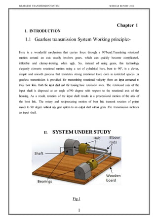
  • 1. GEARLESS TRANSMISSION SYSTEM SEMINAR REPORT 2016 1 Chapter 1 1. INTRODUCTION 1.1 Gearless transmission System Working principle:- Here is a wonderful mechanism that carries force through a 90ºbend.Translating rotational motion around an axis usually involves gears, which can quickly become complicated, inflexible and clumsy-looking, often ugly. So, instead of using gears, this technology elegantly converts rotational motion using a set of cylindrical bars, bent to 90º, in a clever, simple and smooth process that translates strong rotational force even in restricted spaces .A gearless transmission is provided for transmitting rotational velocity from an input connected to three bent links. Both the input shaft and the housing have rotational axes. The rotational axis of the input shaft is disposed at an angle of 90 degree with respect to the rotational axis of the housing. As a result, rotation of the input shaft results in a processional motion of the axis of the bent link. The rotary and reciprocating motion of bent link transmit rotation of prime mover to 90 degree without any gear system to an output shaft without gears .The transmission includes an input shaft. Fig.1
  • 2. GEARLESS TRANSMISSION SYSTEM SEMINAR REPORT 2016 2 CONCEPT DRAWING OF MACHINE Fig. 2
  • 3. GEARLESS TRANSMISSION SYSTEM SEMINAR REPORT 2016 3 1.2 WORKING The Gearless transmission or El-bow mechanism is a device for transmitting motion at any fixed angle between the driving and driven shaft. The synthesis of this mechanism would reveal that it comprises of a number of pins would be between 3 to 8 the more the pins the smoother the operation. These pins slide inside hollow cylinders thus formatting a sliding pair. Our mechanism has 3 such sliding pairs. These cylinders are placed in a Hollow pipe and are fastened at 120* to each other. This whole assembly is mounted on brackets wooden table. Power is supplied by an electric motor. The working of the mechanism is understood by the diagram. An unused form of transmission of power on shaft located at an angle. Motion is transmitted from driving to the driven shaft through the roads which are bent to conform to the angles between the shafts. These roads are located at in the holes equally spaced around a circle and they are free to slide in & out as the shaft revolves. This type of drive is especially suitable where quite operation at high speed is essential but only recommended for high duty. The operation of this transmission will be apparent by the action of one rod. During a revolution. If we assume that driving shaft “A” is revolving as indicated by arrow the driven shaft B will rotate counter clockwise. As shaft A turns through half revolution C shown in the inner and most effective driving position slides out of both shafts A & B The first half revolution and rod “C” then will be at the top then during he remaining half this rod “C” slide in wards until it again reaches to inner most position shown in Fig. in the meanwhile the other roads have of course passed through the same cycle of movements all rods are successively sliding inwards and outwards. Although this transmission is an old one many mechanics are skeptical about its operation, however it is not only practicable but has proved satisfactory for various applications when the drive is for shafts which are permanently located at given angle. Although this illustration shows a right angle transmission this drive can be applied also to shafts located at intermediate angle between 0* and 90*.In making this transmission, it is essential to have the holes for a given rod located accurately in the same holes must be equally spaced in radial and circumferential directions, be parallel to each rod should be bent to at angle at which the shaft are to be located. If the holes drilled in the ends of the shafts have “blind” or closed ends, there ought to be a small vent at the bottom of each rod hole for the escape of air compressed by the pumping action of the rods.
  • 4. GEARLESS TRANSMISSION SYSTEM SEMINAR REPORT 2016 4 1.3 APPLICATION The featured product has its widest application as an extension for a socket wrench. Here the design makes it easy to reach fasteners in the automotive and other mechanical industries, where direct access to bolts and screws is often limited. However, the possible applications for this technology extend into numerous fields. Just think of the possibilities for power transmission in push bikes, toysand hand-cranked equipment, or for movement transmission in store and outdoor signage. 1. Driving for all kinds four faced tower clocks. The elbow mechanism was first use in the year 1685 for the famous London tower clock named bigben. 2. The mechanism is invariable used for multiple spindle drilling operation called the gang drilling. 3. Used for angular drilling between 0 to 90 degree position. 4. Lubrication pump for C.N.C. lathe machines. 5. The mechanism is very useful for a reaching a drive at a clumsy location. 6. Air blower for electronic and computer machine. 7. The mechanism has found a very usefully use in electronic and computer technology for multiple. 8. The elbow mechanism is used for movement of periscope in submarines, 9. The year 1685 for the famous London tower clock.
  • 5. GEARLESS TRANSMISSION SYSTEM SEMINAR REPORT 2016 5 Chapter 2 COMPARISON 2.1 COMPARISON OF GEARED DRIVE WITH GEARLESS DRIVE The gearless drive is capable of transmitting motion at any fixed angle between 0* to 90*. The desired effect is also possible with help of bevel gearless differ to a great extent not only in their manufacturing method or working principle but also in other aspects etc. the aspects have been discussed below. I) MANUFACTURING METHODS:- Bevel gears, which are straight teeth or spiral teeth are manufactured on special purposes machines like Gearless machines. These required large amount of calculation and every pair or set of gear are made together and there is no interchangeability. The gearless drive has this advantage that it can be machined and manufactured on conventional machines it provide complete freedom of interchangeability. II) WORKING PRINCIPLE:- A gear comprises of a frustum of a cone with teeth out on its periphery. The driving gear mounted on the input shaft meshes with the driven gearand thus provides motion at right angle to the input shaft .The working of the gearless drive has been explained in the earlier chapter and it obviously very different from the above. III) CAUSE OF FAILURE:- Starting with the principle that failure Id the result of the stress i.e. condition more severe than the material can with stand. The various type of failures such as pitting, corrosion, erosion, fatigue etc. Cause the wearing of the gear tooth resulting in the tooth leads to the replacement of the entire gear set, which is very expensive. The effect of pitting, erosion, corrosion etc. will be present in the gearless drive also but the effect of these will be not be as severe as in the case of geareddrive, failure will take place in the piston e.g. Either bending or crack Of the pins, but the main advantage is that only particular pin will have to be replaced instead of case of failure.
  • 6. GEARLESS TRANSMISSION SYSTEM SEMINAR REPORT 2016 6 IV) MATERIAL:- The material chosen for any component must (a) Be easily available. (b) Be capable of being processed in the desired examinations and have the necessary physical properties. The gears generally fail due to bending, fatigue and impact and the gears are also responsible for the failure of the components in the gears have to very carefully determine since it may lead to pitting. V) LUBRICATION AND COOLING:- A few open gears drives are lubricated by grease but gear units are usually totally enclosed and oil lubricated. The arrangement for lubrication is simple and easy, since it requires only a leak proof housing in which the gears are placed and oil is filled. This lubricating also acts as cooling medium. The heat generated and it then spreads to otherareas. In the gearless drive lubrication and cooling plays a very major role. The efficiency of the mechanism is affected by lubrication. Although the system of lubrication and cooling complex as discussed in the next chapter but gives good result. Due to sliding contract, between pins and cylinders, heat generated is more and thus effective cooling is amust. VI) TORQUE TRANSMITTUNG CAPACITY:- The gear drive is capable of transmitting very high torque ascompared to the gearless drive which is ment only for low torque applications.
  • 7. GEARLESS TRANSMISSION SYSTEM SEMINAR REPORT 2016 7 VII) LIFE AND EFFICIENCY:- Designed life represents the total period of operation, regardless of any variations of torque or speed, which may occur during that the time industrial. The geared drive is capable of giving an efficiency of about 40% and certain errors like backlash, hunting etc. cannot be eliminated. VIII) Comparison of this drive with gear drive infinite no of speed can be available which cannot toeasily possible in gearbox. IX) Optimum machining is important which require exact machining speed for particular operation which is very difficult to gain for gear drive but can easily available by this drives increase the following. 1)Tool life 2) Productively 3) Energy saving. X) The different speed at eight angle ( 0 to 90) is possible which is not easily possible in gear drive. XI) Efficiency can be increased by increasing no of pins, by precise machining, selecting suitable material and proper lubrication.
  • 8. GEARLESS TRANSMISSION SYSTEM SEMINAR REPORT 2016 8 Chapter 3 3.1 SELECTION OF MATERIAL The proper selection of material for the different part of a machine is the main objective in the fabrication of machine. For a design engineer it is must that he be familiar with the effect, which the manufacturing process and heat treatment have on the properties of materials. The Choice of material for engineering purposes depends upon the following factors: 1. Availability of the materials. 2. Suitability of materials for the working condition in service. 3. The cost of materials. 4. Physical and chemical properties of material. 5. Mechanical properties of material. The mechanical properties of the metals are those, which are associated with the ability of the material to resist mechanical forces and load. We shall now discuss these properties as follows: 1. Strength : It is the ability of a material to resist the externally applied forces 2. Stress: Without breaking or yielding. The internal resistance offered by apart to an externally applied force is called stress. 3. Stiffness: It is the ability of material to resist deformation under stresses. The Modules of elasticity of the measure of stiffness.
  • 9. GEARLESS TRANSMISSION SYSTEM SEMINAR REPORT 2016 9 4. Elasticity: It is the property of a material to regain its original shape after deformation when the external forces are removed. This property is desirable for material used in tools and machines. It may be noted that steel is more elastic than rubber. 5. Plasticity: It is the property of a material, which retain the deformation produced under load permanently. This property of material is necessary for forging, in stamping images on coins and in ornamental work. 6. Ductility: It is the property of a material enabling it to be drawn into wire with the application of a tensile force. A ductile material must be both strong and plastic. The ductility is usually measured by the terms, percentage elongation and percent reduction in area. The ductile materials commonly used in engineering practice are mild steel, copper, aluminium , nickel, zinc, tin and lead. 7. Brittleness: It is the property of material opposite to ductile. It is the property of breaking of a material with little permanent distortion. Brittle materials when subjected to tensile loads snap off without giving any sensible elongation. Cast iron is a brittle material. 8. Malleability: It is a special case of ductility, which permits material to be rolled or hammered into thin sheets, a malleable material should be plastic but it is not essential to be so strong. The malleable materials commonly used in engineering practice are lead, soft steel, wrought iron, copper and aluminium. 9. Toughness: It is the property of a material to resist the fracture due to high impact loads like hammer blows. The toughness of the material decreases when it is heated. It is measured by the amount of absorbed after being stressed up to the point of fracture. This property is desirable in parts subjected toshock animpact loads. 10. Resilience: It is the property of a material to absorb energy and to resist rock and impact loads. It is measured by amount of energy absorbed per unit volume with in elastic limit. This property is essential for spring material.
  • 10. GEARLESS TRANSMISSION SYSTEM SEMINAR REPORT 2016 10 11. Creep: When a part is subjected to a constant stress at high temperature for long period of time, it will undergo a slow and permanent deformation called creep. This property is considered in designing internal combustion engines, boilers and turbines. 12.Hardness: It is a very important property of the metals and has a wide verity of meanings .It embraces many different properties such as resistance to wear scratching, deformation and mach inability etc. It also means the ability of the metal to cut another metal. The hardness is usually expressed in numbers, which are dependent on the method of making the test. The hardness ofametal may bedetermined bythe following test a) Brinell hardness test b) Rockwell hardness test c)Vickers hardness (also called diamond pyramid) test and d) Share scaleroscope. Fig. 3
  • 11. GEARLESS TRANSMISSION SYSTEM SEMINAR REPORT 2016 11 Chapter 4 RAW MATERIAL AND STANDARD MATERIAL Table-1 1 FRAME Ms 1 C section 75x 40x 4 mm 2 MOTER STD 1 0.25 hp 1440 rpm 3 SHAFT Ms 2 Dia 20mm x 350mm 4 HOUSING Ms 2 Dia 95 mm x 62 mm 5 BENT LINK Ms 3 Dia 10 mm x 240 mm 6 PULLEY CI 2 Dia 45 & 250 mm 7 PEDESTAL BEARING CI 4 P204 8 BELT Leather 1 a-56 9 ANGEL MS 1 35 x 35 x 5 mm 10 NUT BOLT WASHER MS 10 M10 11 WELDING ROD - 12 COLOUR -
  • 12. GEARLESS TRANSMISSION SYSTEM SEMINAR REPORT 2016 12 Chapter 5 5.1 MACHINE DESIGN The subject of MACHINE DESIGN deals with the art of designing machine of structure. A machine is a combination of resistance bodies with successfully constrained relative motions which is used for transforming other forms of energy into mechanical energy or transmitting and modifying available design is to create new and better machines or structures and improving the existing ones such that it will convert and control motions either with or without transmitting power. It is the practical application of machinery to the design and construction of machine and structure. In order to design simple component satisfactorily, a sound knowledge of applied science is essential. In addition, strength and properties of materials including some metrological are of prime importance. knowledge of theory of machine and other branch of applied mechanics is also required in order to know the velocity. Acceleration and inertia force of the various links in motion, mechanics of machinery involve the design. 5.2 CONCEPT IN M.D.P. Consideration in Machine Design When a machine is to be designed the following points to be considered: - i) Types of load and stresses caused by the load. ii) Motion of the parts and kinematics of machine. This deals with the iii) Type of motion i.e. reciprocating , Rotary and oscillatory. iv) Selection of material & factors like strength, durability, weight, corrosion resistant, weld ability, machine ability are considered. v) Form and size of the components. vi) Frictional resistances and ease of lubrication. vii) Convience and economical in operation. viii) Use of standard parts. ix) Facilities available for manufacturing. x) Cost of making the machine. xi) Number of machine or product are manufactured
  • 13. GEARLESS TRANSMISSION SYSTEM SEMINAR REPORT 2016 13 5.3 GENERAL PROCEDURE IN MACHINE DESIGN The general steps to be followed in designing the machine are as followed: i) Preparation of a statement of the problem. ii) Purpose of the machine. iii) Selection of groups of mechanism for the desire motion. iv) Calculation of the force and energy on each machine member. v) Selection ofmaterial. vi) Determining the size of component drawing and sending for manufacture. vii) Preparation of component drawing and sending for manufacture. viii) Manufacturing and assembling the machine. Testing of the machine and for functioning Power ofmotor = ¼ H.P=746x.25=186.5N- m/s Rpm ofmotor =1440rpm Power ofmotor = P= 186.5watt. P= 2πN TP /60 Where, N = Rpm of motor = 1440 T = Torque transmitted 186.5 = 2π×140×T/60 T =1.23N-m T=1238N-mm 5.4 DESIGNING OF SHAFT BENDING: The material forces that are developed on any cross section of the shaft give rise to stresses at every point. The internal or resisting moment gives rise to so called bending stresses. TORSION: When the shaft is twisted by the couple such that the axis of the shaft and the axis of the couple coincides, the shaft is subjected to pure torsion and the stresses at any point of cross section is torsion or shear stresses.
  • 14. GEARLESS TRANSMISSION SYSTEM SEMINAR REPORT 2016 14 COMBINED BENDING AND TORSION: In practice the shaft in general are subjected to combination of the above Two types of stresses. The bending stresses may be due to following: 1. Weight of belt. 2. Pull of belts. 3. Eccentric Mounting. 4. Misalignment The torsional movement on the other hand may be due to direct or indirect twisting. Thus any cross-section of the shaft is subjected simultaneously of both bending stresses and torsional stresses. Following stresses are normally adopted in shaft design Max tensile stress = 60 N/mm2 Max shear stress =40N/mm2 Shaft design on basic of study:- Considering 25 % overload Tmax= 1238x1.25=1.525x10 3N-mm The shaft is subject to pure torsional stress Weknow T= 3. 14/16xfs xd3 15250 = 3. 14/ 16 x 70x d3 D =10.20mm Taking factor of safety = 2 D = 10 x2=20mm Same torque is transmitted to bent link shaft Sotorque oneachshaft =T/3 = 15250 /3=5083N mm T= 3. 14/16xfs xd3 5083=3. 14/ 16 x 70x d3 D =7.17 mm Taking factor of safety =1.4 D =7x 1 .4 = 9.8 =10mm
  • 15. GEARLESS TRANSMISSION SYSTEM SEMINAR REPORT 2016 15 Chapter 6 6.1 COST ESTIMATION Cost estimation may be defined as the process of forecasting the expenses that must be incurred to manufacture a product. These expenses take into a consideration all expenditure involved in a design and manufacturing with all related services facilities such as pattern making, tool, making as well as a portion of the general administrative and selling costs. 6.1.1 PURPOSE OFCOST ESTIMATING: 1. To determine the selling price of a product for a quotation or contract so as to ensure a reasonable profit to the company. 2. Check the quotation supplied by vendors. 3. Determine the most economical process or material to manufacture the product. 4. To determine standards of production performance that may be used to control the cost. 6.1.2 THE BUDGET ESTIMATION IS OF TWO TYPES: 1 .material cost 2 .Machining cost 6.2 MATERIALCOST ESTIMATION: Material cost estimation gives the total amount required to collect the raw material which has to be processed or fabricated to desired size and functioning of the components. These materials are divided into two categories. 1.Material for fabrication: In this the material in obtained in raw condition and is manufactured or processed to finished size for proper functioning of the component. 2.Standard purchased parts: This includes the parts which was readily available in the market like Allen screws etc. A list is forecast by the estimation stating the quality, size and standard parts, the weight of raw material and cost per kg. for the fabricated parts.
  • 16. GEARLESS TRANSMISSION SYSTEM SEMINAR REPORT 2016 16 MACHINING COST ESTIMATION: This cost estimation is an attempt to forecast the total expenses that may include to manufacture apart from material cost. Cost estimation of manufactured parts can be considered as judgment on and after careful consideration which includes labour, material and factory services required to produce the required part. 6.3 SPECIFICATION & MANUFACTURING OF PARTS MANUFACTURING PROCESS : The following are the various manufacturing process used in mechanical engineering. 1) PRIMARY SHAPING PROCESS: The process used for the preliminary shaping of the machine component is known as primary shaping process. 2) MACHINE PROCESS : The process used for giving final shape to the machine component,according to planned dimensions is known as machining process. The common operation drilling, boring etc. 3) SURFACE FINISHING PROCESS: The process used to provide a good shape surface finish for the Machine components are known as surface finishing processes. The common operation used for the process are polishing, buffing, lapping etc. 4) JOINING PROCESS : The proces used for joining machine components are known as joining process. The common operation used for this process are soldering, brazing, welding etc.
  • 17. GEARLESS TRANSMISSION SYSTEM SEMINAR REPORT 2016 17 5) PROCESS AFFECTING CHANGE IN PROPERTIES: These are intended to import specific properties to material e.g. heat treatment, hot working, cold rolling etc. COMPONENT:- FRAME CHANNEL MATERIAL:- M.S. CHANNEL MATERIAL SPECIFICATION:- I.S.L.C.40X.75X5 Table -2 (Material specification) SR NO DISCRIPTION OF OPERATION MACHINE USED CUTTING MEASUREMENT TIME 1 Cutting the channel in to length of 1000 mm long Gas cutting machine Gas cutter Steel rule 15 min. 2 Cutting the channel in to length of 480 mm long Gas cutting machine Gas cutter Steel rule 15 min. 3 Filling operation can be performed on cutting side and bring it in perpendicular c.s. Bench vice File Try square 15 min. 4 Weld the channels to the required size as per the drawing Electric arc welding machine ................. Try square 20 min 5 Drilling the frame at required points as per the drawing Radial drill machine Twist drill Vernier calliper 10 min
  • 18. GEARLESS TRANSMISSION SYSTEM SEMINAR REPORT 2016 18 Name of part: pin Material : bright steel Quantity: 3 Table-3 (Housing Assembly) Sr. no. Detail operation m/c used Tool used Accs Mea.inst Name of part: housing Material : bright steel Quantity: 2 1 Marking on shaft - - - Scale 2 Cutting as per dwg Power hack saw Hock saw blade Jig & fixtures Scale 3 Facing both side of shaft Lathe machine Single point cutting tool Chuck Vernier calliper 4 Turning as per dwg size - - - - 5 Bending Gas cutting Right angle Vice - 6 Filling on both end Flate file Vice -
  • 19. GEARLESS TRANSMISSION SYSTEM SEMINAR REPORT 2016 19 Chapter 7 POSSIBLE IMPROVEMENTS AND ADVANCES The project designed and manufactured by us although is only model and has not undergone any extensive research or study but we are quite confident that it is possible to improve it’s efficiency to a considerable extent by improving the manufacturing techniques and also by corporative certain modifications. This device can also be used for various other applications besides just transmitting motion at desired angle those applications have discussed in detailing the following: - 7.1 METHOD OF IMPROVING EFFICIENCY: - Manufacturing of improving efficiency: - The main motion is transmitted with the help of a sliding pair which formed between pin & the cylinder. These pins have to be lapped and cleaned and it should be capable of providing complete interchangeability similarly with the cylinder, they too have to be hone or lapped so a to providesmoothsurface finish. This willresultinless frictionalloss and loss heatgeneration. 7.2 LIBRICATION AND COOLING METHODS: - Lubrication and cooling are a must in sliding members. One of the simple techniques applied for lubrication can be to drill oil holes in the cylinder bod for fill than up with oil. But this technique will not be very effective since theweight and use of cylinders will increase.
  • 20. GEARLESS TRANSMISSION SYSTEM SEMINAR REPORT 2016 20 7.3 MODIFICATION: - One of the methods by which efficiency or performance can be enhanced is by increasing the number ofpins. From theworkingof themechanism weknowthat thepin at the inner most position is the drawing pin the pins the mechanism. Thus if the no. required for the next pin to attain the inner most position is considerable reduced and thus the performance of the mechanism &its life increases. 7.4 POSSIBLE ADVANCE: We can also use this transmission system as, 1.As lubricating pump while transmitting power. 2.Steam engine (eliminating the crank of shaft & complicated valve system). 7.5 LUBRICATING PUMP : The small change which have to incorporate for this purpose is to place stationary disc attherearand it so fits with the cylinder that it avoids leak ages. WORKING: The slot position and length is so that adjusted that when pin is at inner most position cylinder meshes with the suction port & suction of oil is started the sloter mains open till pin given maximum outward stroke, after that cylinder enclosed by the discs. Now the pin starts moving inwards and thus compression stroke commences. The delivery slot location is so adjusted that after the completion of 80 to 85% of compression stroke, the cylinder meshes with the delivery stroke & thus the compressed fluid is discharged at high pressure. The delivery slot length was such adjusted that remains in mesh with cylinder for 15to 20% of compression for complete delivery of the compressed fluid. The suction slot length is adjusted for complete outward stroke of pin.
  • 21. GEARLESS TRANSMISSION SYSTEM SEMINAR REPORT 2016 21 ADVANTAGES 1) Mechanism is very simply dueto elimination of value mechanisms. 2) Mechanism is small & compact. 3) No crank & crank shaft are necessary. 4) Lesser vibration because the reciprocating force are perfectly balanced. 5) Smooth & high speed operation can be easily obtained bycauseofeliminationof thevalue setting linkage. DISADVANTAGES 1) It is only useful for small power generation. 2) It requires at least six cylinder piston pair. 3) Priming is always necessaryforstartingthe engine.
  • 22. GEARLESS TRANSMISSION SYSTEM SEMINAR REPORT 2016 22 CONCLUSION Some successful mechanical devices function smoothly however poor fly they Are made while other does this only by virtue of a accurate construction & fitting of their moving parts. This projects which looks very simple & easy to construct was actually Very difficult to conceive & imagine without seeing an actual one in practice. It is an event a fact in the creative mental process nit the forces, which predominate among the schemes of the active tinkers. Motions demands to be studied first &we have done that very thing. We find that while acceptable analysis for existing mechanism can often be Made quite easily we cannot without insight & imagination make effective synthesis of new mechanism hence we are mould to present this our project gear less transmission at 90*(El-bow mechanism) which we have managed to successfully deviceafter long & hard inputin conceiving its working principle.
  • 23. GEARLESS TRANSMISSION SYSTEM SEMINAR REPORT 2016 23 REFERENCE Elaheh Hassanzadeh Toreh, Mehdi Shahmohammadi and Nazim Khamseh, Kinematic and kinetic study of rescue robot by using Solidworks software, Research Journal of Sciences, Engineering and Technology, Published May 20, 2013. [2] Kuang Hua C., Motion Simulation and Mechanism Design with solidworks Motion, SDC Publications, Schroff Development Corporation, File No. 978-1- 58503-669-1-1, 2011. [3] Gadhia Utsav D., Quarter Model of Wagon-R car’s Rear Suspension, analysised by using ADAMS, International Journal of Engineering Research & Technology, Vol.1 Issue July 5, 2012. [4] Assad Anis, Simulation of Slider Crank Mechanism using ADAMS software, International Journal of Engineering & Technology, Vol:12 No:04, August 2012. [5] R. M. Jadeja, D. M. Chauhan, A Review on Design, Analysis and Manufacturing of Spiral Bevel Gear, International Journal of Engineering Research & Technology, Vol: 02 Issue 4 April 2013. [6] A. A. Yazdani, J. Jin, G. Lepage Jupiter and G. Cozzonlino, Multibody Dynamics Simulation of an Integrated Landing Gear System using MSC ADAMS software, Users Conference Irvine, CA, May 7-8, 2013. [7] Mohammad Ranjbarkohan, Mansour Rasekh, Abdul Hamid Hoseini, Kamran Kheiralipour and Mohammad Reza Asadi, Kinematic and kinetic analysis of slider-crank mechanism in otto linear four cylinder Z24 engine, Journal of Mechanical Engineering Research Vol. 3(3), pp. 85-95, March 2011.
  • 24. GEARLESS TRANSMISSION SYSTEM SEMINAR REPORT 2016 24