1. North South University
Physics 108 (Lab Manual)
Experiment No: 1
Name of the Experiment: Verification of Ohm’s law by measuring resistance in series and
parallel circuits.
Objective:
To measure resistance in series and parallel circuit and show that it satisfies Ohm’s law.
Equipment:
1. Resistors R1, R2
2. DC Voltage Source
3. Connecting Wires
4. Graph Paper
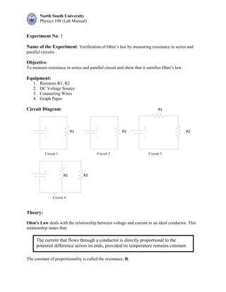
Circuit Diagram:
Theory:
Ohm's Law deals with the relationship between voltage and current in an ideal conductor. This
relationship states that:
The constant of proportionality is called the resistance, R.
R1 R2
R1
R1
R2
R2
Circuit 1 Circuit 2 Circuit 3
Circuit 4
The current that flows through a conductor is directly proportional to the
potential difference across its ends, provided its temperature remains constant.
2. North South University
Physics 108 (Lab Manual)
Ohm's Law is given by: V = I x R
Where, V = voltage in volts (V)
I = current in amps (A)
R = resistance in ohms ( )
To solve for any one quantity given the other two, first arrange the letters E, I, and R in a triangle
like this:
If two of the three quantities are known, then to determine the unknown
quantity, eliminate it from the triangle. The position of the two remaining
shows the relationship.
Series circuits
A series circuit is a circuit in which resistors are arranged in a chain, so the current is the same
through each resistor. The total resistance of the circuit is found by simply adding up the
resistance values of the individual resistors:
equivalent resistance of resistors in series : R = R1 + R2 + R3 + ...
Parallel circuits
A parallel circuit is a circuit in which the resistors are arranged with their heads connected
together, and their tails connected together. The current in a parallel circuit breaks up. The
voltage across each resistor in parallel is the same.
The total resistance of a set of resistors in parallel is found by adding up the reciprocals of the
resistance values, and then taking the reciprocal of the total:
Equivalent resistance of resistors in parallel: 1 / R = 1 / R1 + 1 / R2 + 1 / R3 +...
Procedure:
1. Connect R1 to the DC Voltage Source (as shown in circuit 1)
2. Set the value of DC Voltage Source to 0V and measure current across R1
3. Continue the process for 2V, 4V and 6V respectively
4. Plot I-V graph in a graph paper
5. Find R1 which is the gradient of the straight line
6. Connect circuit 2, 3 and 4 respectively
7. Conitune the same process to find R2, Rseries and Rparallel
8. Verify if the resistance found from circuit 3 and 4 follow the equations of series and
parallel resistance
3. North South University
Physics 108 (Lab Manual)
Data and Result:
R1: R2
V
(Volts)
Theor
etical
value
I
(A)
R from
Ohm's
Law
(Ω)
Avg
R
(Ω)
R from
slope
(Ω)
V
(Volts)
Theor
etical
value
I
(A)
R from
Ohm's
Law (Ω
Avg
R
(Ω)
R from
slope
(Ω)
0 0
2 2
4 4
6 6
Rseries
Rparall
al
V
(Volts)
Theor
etical
value
I
(A)
R from
Ohm's
Law
(Ω)
Avg
R
(Ω)
R from
slope
(Ω)
V
(Volts)
Theor
etical
value
I
(A)
R from
Ohm's
Law
(Ω)
Avg
R
(Ω)
R from
slope
(Ω)
0 0
2 2
4 4
6 6
Report:
1. Data sheet.
2. 4 I-V graphs for R1, R2, Rseries and Rparallel.
3. Discussion and comparison.
4. Calculate the percentage of error between the values of R.