
Recommandé
Contenu connexe
Tendances
Tendances (20)
En vedette
Similaire à Networking Ethernet
Similaire à Networking Ethernet (20)
Dernier
Dernier (20)
Networking Ethernet
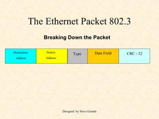
- 1. The Ethernet Packet 802.3 Destination Address Source Address Type Data Field CRC - 32 Breaking Down the Packet
- 2. The Ethernet Packet 802.3 Destination Address Source Address Type Data Field CRC - 32 Breaking Down the Packet 02 60 8C 01 02 04 Card Vendor Node ID 3COM 02 60 8C 01 02 04 The Node that will receive the packet
- 3. The Ethernet Packet 802.3 Destination Address Source Address Type Data Field CRC - 32 Breaking Down the Packet 02 60 8C 04 05 06 Card Vendor Node ID 3COM 02 60 8C 01 02 04 The Node that is transmitting the packet 02 60 8C 04 05 06
- 4. The Ethernet Packet 802.3 Destination Address Source Address Type Data Field CRC - 32 Breaking Down the Packet 08 00 02 60 8C 01 02 04 ID of Protocol (TCP/IP) 02 60 8C 04 05 06 08 00
- 5. The Ethernet Packet 802.3 Destination Address Source Address Type Data Field CRC - 32 Breaking Down the Packet The Data Field is an area that contains both the header and the user data 02 60 8C 01 02 04 The first 30 bytes of the IPX Structure is referred to as the header 02 60 8C 04 05 06 08 00
- 6. The IPX Data Field User Data 546 Bytes Header = 30 Bytes Checksum (2 BYTES) Length (2 BYTES) Transport Control (1 BYTE) Packet Type = 1 (1 BYTE) Destination Network (4 BYTES) Destination Node (6 BYTES) Destination Socket = 0453 (2 BYTES) Source Network (4 BYTES) Source Node (6 BYTES) Source Socket (2 BYTES)
- 7. The Ethernet Packet 802.3 Breaking Down the Packet Checksum (2 BYTES) The checksum contains 16 bits which check the integrity of the packet If the feature is disabled, the contents will read FFFF Destination Address Source Address Type Data Field CRC - 32 02 60 8C 01 02 04 02 60 8C 04 05 06 08 00
- 8. The Ethernet Packet 802.3 Breaking Down the Packet Checksum (2 BYTES) Length (2 BYTES) The length Min 30 Bytes Max 576 - 30 bytes Note: With LAN communication the number may be as high as the transmission medium allows. 1500 - Ethernet 1496 - 802.3 4472 - 4 Mbs Token Ring Destination Address Source Address Type Data Field CRC - 32 02 60 8C 01 02 04 02 60 8C 04 05 06 08 00
- 9. The Ethernet Packet 802.3 Breaking Down the Packet Checksum (2 BYTES) Length (2 BYTES) Transport Control (1 BYTE) The Transport Control Initially set to 0 Provides the maximum number of hops Note: As the data traverses through the network the number of hops from router to router is counted. If the number goes higher than 15 the packet is discarded Destination Address Source Address Type Data Field CRC - 32 02 60 8C 01 02 04 02 60 8C 04 05 06 08 00
- 10. The Ethernet Packet 802.3 Breaking Down the Packet Checksum (2 BYTES) Length (2 BYTES) Transport Control (1 BYTE) Packet Type = 1 (1 BYTE) The Packet Type Provides a description about the data within the data field Destination Address Source Address Type Data Field CRC - 32 02 60 8C 01 02 04 02 60 8C 04 05 06 08 00
- 11. The Ethernet Packet 802.3 Breaking Down the Packet Checksum (2 BYTES) Length (2 BYTES) Transport Control (1 BYTE) Packet Type = 1 (1 BYTE) Destination Network (4 BYTES) The length Min 30 Bytes Max 576 - 30 bytes Destination Address Source Address Type Data Field CRC - 32 02 60 8C 01 02 04 02 60 8C 04 05 06 08 00
- 12. The Ethernet Packet 802.3 Breaking Down the Packet Checksum (2 BYTES) Length (2 BYTES) Transport Control (1 BYTE) Packet Type = 1 (1 BYTE) Destination Network (4 BYTES) Destination Node (6 BYTES) The length Min 30 Bytes Max 576 - 30 bytes Destination Address Source Address Type Data Field CRC - 32 02 60 8C 01 02 04 02 60 8C 04 05 06 08 00
- 13. The Ethernet Packet 802.3 Breaking Down the Packet Checksum (2 BYTES) Length (2 BYTES) Transport Control (1 BYTE) Packet Type = 1 (1 BYTE) Destination Network (4 BYTES) Destination Node (6 BYTES) Destination Socket = 0453 (2 BYTES) The length Min 30 Bytes Max 576 - 30 bytes Destination Address Source Address Type Data Field CRC - 32 02 60 8C 01 02 04 02 60 8C 04 05 06 08 00
- 14. The Ethernet Packet 802.3 Breaking Down the Packet Checksum (2 BYTES) Length (2 BYTES) Transport Control (1 BYTE) Packet Type = 1 (1 BYTE) Destination Network (4 BYTES) Destination Node (6 BYTES) Destination Socket = 0453 (2 BYTES) Source Network (4 BYTES) The length Min 30 Bytes Max 576 - 30 bytes Destination Address Source Address Type Data Field CRC - 32 02 60 8C 01 02 04 02 60 8C 04 05 06 08 00
- 15. The Ethernet Packet 802.3 Breaking Down the Packet Checksum (2 BYTES) Length (2 BYTES) Transport Control (1 BYTE) Packet Type = 1 (1 BYTE) Destination Network (4 BYTES) Destination Node (6 BYTES) Destination Socket = 0453 (2 BYTES) Source Network (4 BYTES) Source Node (6 BYTES) The length Min 30 Bytes Max 576 - 30 bytes Destination Address Source Address Type Data Field CRC - 32 02 60 8C 01 02 04 02 60 8C 04 05 06 08 00
- 16. The Ethernet Packet 802.3 Breaking Down the Packet The length Min 30 Bytes Max 576 - 30 bytes Destination Address Source Address Type Data Field CRC - 32 02 60 8C 01 02 04 02 60 8C 04 05 06 08 00 Checksum (2 BYTES) Length (2 BYTES) Transport Control (1 BYTE) Packet Type = 1 (1 BYTE) Destination Network (4 BYTES) Destination Node (6 BYTES) Destination Socket = 0453 (2 BYTES) Source Network (4 BYTES) Source Node (6 BYTES) Source Socket (2 BYTES)
- 17. The Ethernet Packet 802.3 Destination Address Source Address Type Data Field CRC - 32
- 18. The Ethernet Packet 802.3 Destination Address Source Address Type Data Field CRC - 32 The address of the immediate recipient of the message
- 19. The Ethernet Packet 802.3 Destination Address Source Address Type Data Field CRC - 32 The address of the sender of the packet
- 20. The Ethernet Packet 802.3 Destination Address Source Address Type Data Field CRC - 32 The type of data within the packet TCP/IP, Apple Talk, XNS etc.
- 21. The Ethernet Packet 802.3 Destination Address Source Address Type Data Field CRC - 32 Contains the upper layer of software headers and the user data
- 22. The Ethernet Packet 802.3 Destination Address Source Address Type Data Field CRC - 32 Contains the CRC so packet integrity can be analyzed by the algorithm
- 23. Ethernet CSMA/CD Carrier Sense Multiple Access With Collision Detection
- 24. Ethernet Mediums Thick Net = 10BASE5 Thin Net = 10Base2 UTP = 10 BASE T
- 25. Ethernet Mediums Wiring Categories for UTP = Unshielded Twisted Pair Category 3 up to 10 Mbps Category 4 up to 20 Mbps Category 5 up to 100 Mbps UTP = 10 BASE T
- 26. Ethernet WS-B WS-A Both stations listen for the carrier. After detecting that the line is clear:
- 27. Ethernet Collision Both Packets A&B try to contend for the line at the same time resulting in: WS-B WS-A A B
- 28. The Seven Layer OSI Application Presentation Session Transport Network Data Physical
- 29. The Seven Layer OSI Application Presentation Session Transport Network Data Physical Protocol describing the transmission method over the physical media Ethernet over 10BaseT
- 30. The Seven Layer OSI Application Presentation Session Transport Network Data Physical Construction and Reconstruction of the Packet
- 31. The Seven Layer OSI Application Presentation Session Transport Network Data Physical Finds the most efficient route SPX/IPX & TCP/IP
- 32. The Seven Layer OSI Application Presentation Session Transport Network Data Physical Performs Error Checking
- 33. The Seven Layer OSI Application Presentation Session Transport Network Data Physical Establishes the logical communication between two nodes on the network
- 34. The Seven Layer OSI Application Presentation Session Transport Network Data Physical Reformats, Decodes or Compresses the information for presentation to the Session or Application Layer
- 35. The Seven Layer OSI Application Presentation Session Transport Network Data Physical Communication and interface to the network segment of the Application Program Excel, Word, Etc.
- 36. Workstation 1 Workstation 2 T S P A N D T S P A N D Cable Physical T S P A N D Datalink T S P A N Network T S P A Transport S P A Session P A Presentation A Application T S P A N D Cable Physical T S P A N D Datalink T S P A N Network T S P A Transport S P A Session P A Presentation A Application T S P A N D
- 37. Bridges The function of a bridge is to join two networks and pass only packets that belong on a specific network. In other words the bridge acts a packet Filtering device. A B
- 41. Token Ring
- 42. Token Ring The packet circulates around the ring until it finds its destination station The Information is placed in the packet and sent from the originating to the destination station Station 1 Station 2 Station 3 Station 4