1. 0
0
1
1
2
2
3
3
4
4
5
5
6
6
7
7
8
8
9
9
10
10
11
11
12
12
13
13
14
14
A A
B B
C C
D D
E E
F F
G G
H H
I I
J J
PS
311.201 Vrms
60 Hz
0°
R2
16.224
A2
9.615 A
+ -
L1
50.31365mH
XWM3
V I
C1
80.761 F
A4
0 A
+
-
A3
9.615 A
+
-
S1
XWM4
V I
R4
0.01
R1
10
U1
240 V
+
-
U2
96.155 V
+ -
XWM5
V I
C2
48 F
R3
0.01
S2
A1
9.616 A
+
-
A
B
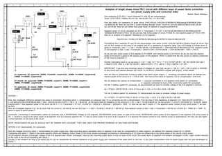
S1 oppenned; S2 oppenned: XWM3: P=2424W, cosphi=0.81; XWM5: P=1500W, cosphi=0.65;
XWM4: P=1500W, cosphi=0.65.
S1 closed; S2 oppenned: XWM3: P=2002W, cosphi=1; XWM5: P=1588W, cosphi=1;
XWM4: P=1588W, cosphi=0.65.
S1 oppenned; S2 closed: XWM3: P=2424W, cosphi=1; XWM5: P=1500W, cosphi=0.65;
XWM4: P=1500W, cosphi=0.65.
Analysis of single phase mixed RLC circuit with different ways of power factor correction
(on power supply side and consumer side)
Author: Samir Ahmadov
First analysing of R1-R2-L1 circut (Switches S1 and S2 are disconnected):
Given: U=311.201V, f=60Hz, R1=10 Om, R2=16.224 Om, L1= 50.31365
First lets define full impedance of given circuit: Z=R1+R2+jXL1=26,224+18.96799=32.365e^jarctg(18.96799/26.224)=
=32.365e^j35.88. Now we can find a current flowing through circuit: I=U/Z=311.201/(32.365e^j35.88)=9.615e^-j35.88
So, phi=35.88. Here we can define that power factor of network is cosphi=cos35.88=0.81.
Apparent power of circuit calculated as S=U x I*(reversed) = 311.201 x 9.615e^j35.88=2992e^j35.88=2992cos35.88+
+j2992sin35.88=2424+j1753.6. So we can see thar Active power of circuit P=2424 W, and reactive power Q=1753.6 VAR
Now let us analyse A-B segment. Resistance of A-B segment:
Zab=R2+jXL=16.224+j18.96799=24.96e^jarctg(18.96799/16.224)=24.96e^j49.458
Concidering that if switches S1 and S2 are disconnected, then same current I=9.615e^-j38.88 is flowing trough all circuit, then
we can find voltage on A-B point (if we imagine that R1 is resistance of supplying cable, then A-B Voltage is voltage which is
given to consumer). Uab = I x Zab = 9.615e^-j38.88 x 24.96e^j49.458 = 240e^j(49.458-35.88)=240e^j13.578. Apparent power
of A-B segment is Sab = Uab x I*(reversed) = 240e^j13.578 x 9.615e^j38.88 = 2307.6e^j49.458 = 1500 + j1753.6.
As we can see, active power of A-B segment is P=1500W, and reactive power is Q=1743.6. As we can see that reactive
power of full circuit is equal to the reactive power of A-B segment. Which is means that the only source of reactive component
of the circuit is inductive L1.
Another interresting issue is: as we know U = Ur1 + Uab; Ur1 = R1 x I = 10 x 9.615e^-j38.88 = 96.15e^-j38.88 and Uab =
= 240e^j13.578. Then U = 96.15e^-j35.88 + 240e^j13.578 = 77.9 - j56.34 + 233.3 +j56.34 = 311.201
IMPORTANT: if we sum only numerical values of voltages Ur1 and Uab, we get U = 96.15 + 240 = 336.15 which is WRONG.
At any circuit with reactive element WE HAVE TO ALWAYS CONSIDER complex part (e^jphi) of the values!
Now we have to compencate circuite to make power factor equal cosphi = 1. According calculations above we defined that
reactive power of the circuit is Q = 1753.6 VAR. We have to find value of Capacitor (C) for compencation. Q=E^2/Xc;
We wil analyze two options of compencation: 1. capacitor connected to A-B segment (only switch S1 connected);
2. capacitor connected to input of the circuit (only switch S2 connected)
For the 1 method (switch S1 connected, S2 disconnected) we have to concider voltage of the A-B segment in formula:
Xc = E^2/Q = 240^2/1753.6 = 32.8; C=1/(w x Xc) = 1/(2 x 3.14 x 60 x 32.8) = 80 mkF
For the 2 method (switch S2 connected, S1 disconnected) we have to consider voltage of power supply:
Xc = E^2/Q = 311.201^2/1753.6 = 55.23; C=1/(w x Xc) = 1/(2 x 3.14 x 60 x 55.23) = 48 mkF
OPTION 1
Now, lets investigate difference between two ways of connection. According option 1, compensation at consumer side, S1 is connected and S2 is disconnected. First we have to find resistance of segment A-B. Zab=(16.224+j18.96799) x
x (-j32.845)/(16.224+j18.96799-j32.845) = (623 - j532.9)/(16.224-j13.877) = 38.4 - j0 = 38.4e^-j0. At the same time full resistance of the circuit is Z = R1 + Zab = 10+38.4=48.4e^-j0. So full current I = U/Z=311.201/48.4e^-j0 = 6.43e^j0, where
cosphi=cos0=1. Now apparent power of the circuit will be S = U x I*(reversed) = 311.201 x 6.43e^-j0 = 2002e^j0 = 2002cos0 + j2002sin0 = 2002 + j0. Now we can see if cosphi = 1, the apparent power consist of only active power P, as soon
as Q=0.
Now we investigate segment A-B. As we know that full current is I=6.43e^j0, we can find Uab = I x Zab = 6.43e^j0 x 38.5e^-j0 = 246.9e^-j0. Now apparent power is Sab = Uab x I*(reversed) = 246.9e^-j0 x 6.43e^-j0 = 1588e^-j0 = 1588 + j0,
which is equal to active power P.
Conclusion: Connecting of compensation system at consumer side is INCREASING Voltage on A-B segment, DECREASING active power on input of the circuit, INCREASING active power of A-B segment! In this segment A-B active power of
R2 - L1 branch is equal to the active power of all segment A-B. It is because segment R4 - C1 has no active power P as soon as it is equal to 0. It is because this branch consist of only reactive power Q (capacitance). We also can see higher
current reduction on the input of the circuit
NOTE: RESISTANCES R4 and R3 SHOULD NOT BE TAKKEN INTO ACCOUNT. THEY ARE USED FOR PROPER WORKING OF MULTISIM SOFTWARE.
OPTION 2 (S1 disconnected, S2 connected):
Now lets analyze according option 2 compenstation at power supply side. Here according above calculated value of capacitor to be used for compensation to make cosphi=1 we defined that capacitor should be C= 48mkF.
Comparing with option 1, option 2 has some specifics which are following: Active Power of full circuit remain unchanged (connecting or disconnecting of C2 does not influencing to the active power of the circuit), active power
of A-B segment remains unchanged, voltage of the A-B segment also remain unchanged. Here we are improving power factor of only on input of the circuit. But power factor of segment A-B ramains unchanged (=0.65). Lower current reduction
on the input of the circuit comparing with option 1.
Actually in real situation we have to be aware that R1 can be represented as internal resistance of the power supply plus resistance of the cable which is very low.. In this case compensation even on power supply side can give advantages of
Option 1.