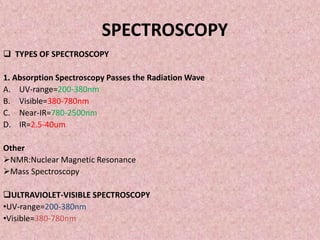
SlideShare une entreprise Scribd logo
1  sur  68
SPECTROSCOPY
 TYPES OF SPECTROSCOPY
1. Absorption Spectroscopy Passes the Radiation Wave
A. UV-range=200-380nm
B. Visible=380-780nm
C. Near-IR=780-2500nm
D. IR=2.5-40um
Other
NMR:Nuclear Magnetic Resonance
Mass Spectroscopy
ULTRAVIOLET-VISIBLE SPECTROSCOPY
•UV-range=200-380nm
•Visible=380-780nm
It is used to measure the multiple bonds or atomic conjugation within the
molecule. The UV-Visible region is subdivided as below
• Vacuum UV: 100-200 nm
• Near UV: 200 to 400 nm
• Visible region: 400 to 750 nm
1. Basics of UV Light Absorption:
 UV Light Absorption Ultraviolet/visible spectroscopy involves the absorption
of ultraviolet/visible light by a molecule causing the promotion of an electron
from a ground electronic state to an excited electronic state Absorption of this
relatively high-energy light causes electronic excitation.
 The easily accessible part of this region (wavelengths of 200 to 800 nm) shows
absorption only if conjugated pi-electron systems are present.
2. Electromagnetic Spectrum
3.Electronic spectroscopy
 When molecule absorb the energy , it results in electronic transition.
 Electron promotion will be from the highest occupied molecular orbital
(HOMO) to the lowest unoccupied molecular orbital (LUMO) and the
resulting species is called an excited state.
Types of Transitions:
Types of Transitions There are several types of electronic transitions
available to a molecule including:
• σ to σ * (alkanes)
• σ to π * (carbonyl compounds)
• π to π * (alkenes, carbonyl compounds, alkynes, Azo compounds)
• ή to σ * (oxygen, nitrogen, sulfur, and halogen compounds)
• ή to π * (carbonyl compounds)
4. Electronic transactions involved
σ * (anti-bonding)
σ *
ή σ * σ
E
π * (anti-bonding)
ή π * π *
ή (non-bonding)
π π * π σ *
π (bonding)
σ π *
σ (bonding)
σ σ * Transitions:
 σ σ * Transitions an electron in a bonding σ orbital is excited to the
corresponding antI bonding orbital. The energy required is large.
 For example, alkanes as methane (which has only C-H bonds, and can only
undergo σ σ * transitions) shows an absorbance maximum at 125 nm.
Absorption maxima .
 Due to σ σ * transitions are not seen in typical UV-Visible spectra (200 -
700 nm). σ bonds are very strong and requires higher energy of vacuum
UV.
ή σ * Transitions:
ή σ * Transitions Saturated compounds containing atoms with lone pairs (non-
bonding electrons) are capable of ή σ * as transitions. These transitions
usually need less energy than σ σ * transitions.
 They can be initiated by light whose wavelength is in the range 150 - 250 nm.
The number of organic functional groups with n σ * peaks in the UV region is
small.
 These transitions are involved in saturated compound with one hetero atom
with unshared pair of electron i.e. saturated halides, ethers, aldehide,
ketones, amines etc.
 These transitions are sensitive to hydrogen bonding e.g. alcohol and ethers
which absorbs at wavelength shorter than 185 nm therefore used as a solvent
in UV.
π π * Transitions:
 π π * Transitions For molecules that possess π bonding as in alkenes, alkynes,
aromatics, acyl compounds or nitriles, energy that is available can promote
electrons from a π Bonding molecular orbital to a π Antibonding molecular
orbital ( π * ). This is called a π π * transition.
 The absorption peaks for these transitions fall in an experimentally
convenient region of the spectrum (200 - 700 nm).
 These transitions need an unsaturated group in the molecule to provide
the π electrons.
ή π * Transitions:
 ή π * Transitions Even lone pairs that exist on Oxygen atoms and Nitrogen
atoms may be promoted from their non-bonding molecular orbital to a π
antibonding molecular orbital within the molecule. This is called an ή π *
transition
 These are available in compounds with unsaturated centers. e.g. Alkenes.
They requires lowest energy as compare to others.
Terminology
Chromaphore:
 A covalently bonded unsaturated group responsible for electronic
absorption.
 These are group of atoms that absorbs light whether or not a color is thereby
produced. Eg c=c, c=o, No2 etc
 A compound containing chromaphore is called chromogen. There are two
types of chromaphore .
 Independent chromaphore: single chromaphore is sufficient to import color
to the compound e.g. Azo group
 Dependent chromaphore: When more than one chromaphore is required to
produce color. Eg acetone having 1 kentone group is colorless where as
diacetyl having two kentone groups is yellow.
Auxochrome:
 A saturated group with non bonding electron when attached to chromaphore
alters both wavelengths as well as intensity of absorption. Eg OH, NH2, NHR etc.
 A group which extends the conjugation of a chromaphore by sharing of
nonbonding electrons.
•
Bathochromic group:
 The group which deepens the colour of chromaphore is called bathochromic
group. Eg. Primary, secondary and tertiary amino groups.
 Bathochromic shift: (Red shift) shift of lambda max to longer side or less
energy is called bathochromic shift or read shift. This is due to substitution or
solvent effect.
Hypsochromic shift:
 (Blue shift) shift of lambda max to shorter side and higher energy is called
hypsochromic or blue shift. Eg solvent effect. That may be increase or
decrease absorption intensity.
SOME SPECTRUMS OF ORGANIC ANALYTES
Instrumentation:
 A beam of light from a visible and/or UV light source (colored red) is separated
into its component wavelengths by a prism or diffraction grating.
 Each monochromatic (single wavelength) beam in turn is split into two equal
intensity beams by a half-mirrored device.
 One beam, the sample beam (colored magenta), passes through a small
transparent container (cuvette) containing a solution of the compound being
studied in a transparent solvent.
 The other beam, the reference (colored blue), passes through an identical
cuvette containing only the solvent.
 The intensities of these light beams are then measured by electronic detectors
and compared. The intensity of the reference beam, which should have
suffered little or no light absorption, is defined as I0 . The intensity of the
sample beam is defined as I . Over a short period of time, the spectrometer
automatically scans all the component wavelengths.
Solvent effect: :
 Different compounds may have very different absorption maxima and
absorbances.
 Intensely absorbing compounds must be examined in dilute solution, so that
significant light energy is received by the detector, and this requires the use of
completely transparent (non-absorbing) solvents.
 The most commonly used solvents are water, ethanol, hexane and
cyclohexane. Solvents having double or triple bonds, or heavy atoms (e.g. S, Br
& I) are generally avoided.
Choice of Solvent:
 First criteria for good solvent are that it does not absorb uv-radiation in the
same region. As the substance whose o-absorptivity is not meaning that it
does not absorb radiation.
 Example: The solvent do not contain conjugated system H2O, ETHANOL (95%),
HEXANE,.
 Second criteria for absorption if it on fine structure on absorption band. Non-
polar solvent (not contain) do not make H-bond with the solute (organic
solvent) and spectrum of solvent is approximate to gases state (steam is
puriest form), in which fine structure often observe. In molar solvent the H-
bonding forms a solute-solvent complex and fine structure may disappear.
 It should contain polar system and conjugated form.
UV-Visible spectrum:
 UV-Visible spectrum A spectrum is a plot of the intensity of energy detected
versus the wavelength
 In case of single band of wavelength, < 220nm usually indicate ή- σ * (amine
NH3), alcohol, ether and thiols .
 Exception: ή- π * (cyano group).it can identify because of its weak transition
absorbtivity 100 (ether, alcohols and amines).which is further identify by IR.
 A single band of low absorbtivity,10-100,at 250-360nm,indicate ή- π *
transition ,indicate(CN,C=O,COOH,COR,N=N,C=N,NO2).
 Two bands of medium intensity, absorbtivity 1000-10.000 both with Lambda
(λ) above 200nm indicates aromatic system.(polynuclear aromatic substance a
3rd band appear near 200nm.where it cannot be observe.
 Bands of high intensity, absorbtivity, 10,000-20,000 appear above
210nm.Generally represent alpha-beta unsaturated ketones, dienes, and
polyene.
 Simple ketones,acids,esters,amides and other compounds containing both π
system and unsaturated electron pairs shows two absorption.
 Compounds that are highly colored, exhibit their spectra in visible region,
unlikely to contain long chain conjugated system or polycyclic aromatic system
chromaphore.
 If an organic compound does not absorb uv-visible radiation, it means that the
compounds do not contain conjugated double bonds.
 If an organic compound absorbs uv-vis radiation, it means that the compound
contains a carbonyl group or conjugated double bonds.for example,
conjugated dienes, carbonyl compounds and aromatic compounds all absorb
in the uv-vis region.
APPLICATIONS
 Qualitative and quantitative analysis.
 SOURCE; deuterium lamp, hydrogen lamp.
 VISIBLE –SPECTROSCOPY
 Tungstun tamp,
 IR-SPECTROSCOPY
• RANGE=2.5u-40um
• SOURCE=Zarconium-oxide,
• Rare earth oxide
• , nearst and global.
 IR- radiation is weak; it does supply sufficient energy for bonds in the
molecules to vibrate by stretching or bending.
 As the molecules is subjected to the individual wavelength in the 5000-
667cm-1 range,
 Since different bonds and functional groups at different wavelength, an
infrared spectrum is used to determine the structure of organic molecules.
 For example, carbon-carbon triple-bond is stronger than a carbon-carbon
double bond and requires a shorter wavelength (greater energy) to
stretch).The same consideration apply to carbon-oxygen and carbon-nitrogen
bonds.
An infrared spectrum studied in two section
i. Functional group region
ii. Fingerprint region
i.Functional group region
The area from 5000cm-1-1300cm-1 is called the functional group region. The
bands in this region are particularly useful in determining the type of functional
groups percentage in the molecule.
ii.Finger print region
The area from 1300cm-1 to 667cm-1 is called the fingerprint region. A peak by
peak match of unknown spectrum with the spectrum of the suspected
compound in this region can be used, much like a fingerprint to confirm its
identity.
IR-SPECTRUM
EXAMPLES
METHANOL
BUTANONE
ISOBUTYLAMINE
INSTRUMENTATION
The instrument that determines the absorption IR spectrum of a compound is called IR
spectrophotometer.
TYPES: there are two types.
i. Dispersive –IR spectrometer
ii. Fourier transform Ir spectrometer
Both of these instrument travel spectra of compound in the common range of 4000-
400cm-1.
DIR-spectrometer :
The instrument produce a beam of IR radiation from a hot wire (IR source).The beam of
by means of mirror divided into two parallel beam of equal intensity radiation,
•Beam sample analysis
•Reference
 Both beams can pass through monochromatic, which disperse each into
continuous spectrum of frequencies or IR-light by beam chopper. Which is a
rotating chamber that passes the two beams alternately through a diffracting
gratting serve as prism which varies of frequency or range?
 The thermo-couple detector senses the ratio between the sample and the
reference that what beam has bean absorbed by the sample and which
uneffective.
 After the singnal from the detector is amplifies the recorder cause the
resulting specterum of sample on chart.
 The IR-chart is recorded as a frequency of the IR-radiation charges by the
rotation of the diffraction gratting.
 Disperive spectrum is recorded in frequency domain, It is common to plot
frequency is live transmission.This is recorded as percentage transmitter from
detector from record the ratio of intensity of two beam therefore.
%T=is/ir x100 Is=sample beam intensity Ir=intensity of reference
SAMPLE PREPARATION
 To obtain the IR-spectrum compound is dissolved in a solvent or diluents .This
solution is then will replace in sample beam by pure solvent beam in a
identical beam.
 The instrument automatically subtracts the spectrum of solvent from that of
sample. The instrument also cancel the effect of IR spectrum NO2, CO2.If pure
liquid is analyzed the sample is varyingly in a sample beam and nothing is
inserted in a reference beam.
 When the spectrum of liquid is obtain. The effects of atmospheric gas
automatically cancel, since they are present in both beams.
FTIR-SPECTROSCOPY
 The most common IR-spectrometer are design to consist of optical pathway,
produce a pattern called interferofram,(broader instrument optical
pathway)There is optical pathway to analyses IR interferogram .
 The interferogram is a complex signal but it’s waves like pattern contain all
frequency that make up the IR-spectrum.
 Interferogram is plot of intensity vs. time, called time domain spectrum.
FTIR-SPECTRUM
In chemical analysis, frequency domain spectrum is preferred over time
domain spectrum is a plot of intensity vs. frequency vs. time.
OPEARTION OR WORKING OF FTIR
 Computer interferogram FTIR instrument operate in a single mode to
obtain spectrum .first interferogram of the background being recorded
by example (co2).
 This background interferogram subjected to Fourier transformer which
yield a spectrum of background., then sample is placed into the beam
spectrum is obtain resulting from Fourier transform of interferogram .
 The spectra contain absorption of sample and background and now where
automatical subtract spectrum of background from the sample which identical to
dispersive spectrum.
PREPARATION OF SAMPLE
 To determine the IR-spectrum of compound sample is placed in holder or cell as
must be constructed from ionic substance (NACL), KBr.
 Glass or plastic absorb Irradiation, so it should be not.
 KBr plates are expensive then NACL, and useful in the range of 4000-400cm-1.
 NACL is useful in the range 4000-659cm-1 and band with frequency less than this
value will not be observe ,since only a few band appear bellow 650cm-1.NACL.
LIQUID
 A drop of liquid is placed between a pair of polished and NACL and KBR plot refer
to as salt plates, where plots are squeeze gently a this liquid film are formed
between them. Spectrum of obtain is know next spectrum since solvent.
 Salt plates are water soluble, so analyzing compound must be free from water;
the pair of plate is inserted, into a holder, which fixed into a spectrometer.
SOLIDS
 Following common methods to grounded sample mix with powder KBr melts
and seal the compound into a matrix results in FTIR plot or disc should be
transport, which can be inserted into holder in IR-spectrometer.
 ADVANTAGE: In case of wood plates for disc the spectrum have no interfering
band, since KBr transport down to 4000cm-1.
 DISADVATNTAGE: KBr through absorb water which may interfere with the
spectrum.
METHOD
NUJOL MULL METHOD
 This method is involve straining the compound with mineral oil,nojol to create a
suspension off finely ground sample in mineral oil dispersed in mineral oil. The
thick suspension MULL place between the salt plates then it analyses in the
spectrometer.
 Disadvantage: Mineral oil obscure band over shallow band that may present in
the analyzing compound.
METHOD
DISSLOUTION IN ORGANIC SOLVENT
 It may be used with solid which dissolve in organic solvent, must commonly
CCL4.In case of mineral oil some region of spectrum are it also bind with
solvent. It is also observed in organic solvent (especially at 785cm-1).
 Although it is possible to cancel out the solvent from the spectrum of sample
by computer.
 NUCLEAR MAGNETIC RESONANCE (NMR) SPECTROSCOPY
 Nuclear magnetic resonance spectroscopy involves absorption of
electromagnetic radiation in the radio frequency region.
 Absorption of radio waves in the presence of magnetic field is accompanied by
a special type of nuclear transition, and for this reason we call this type of
spectroscopy nuclear magnetic resonance (NMR) spectroscopy.
 The nuclei of certain atoms behave as if they are spinning chages.Any spinning
charge creates a magnetic field and behaves as if it were a tiny bar magnet, Of
the three most common in organic compound, only the hydrogen nucleus
proton behaves in this manner.
 When a proton in an organic molecule is placed in a strong magnetic field, it
can align with the field or against it
 In the more stable low-energy state, it is aligned with the magnetic field. (Up
field).that appears toward left on chart paper...
 If energy is supplied in the form of radio waves of exactly the right frequency,
radiation will be absorbed and the nucleus will flip and align against the applied
magnetic field in the less stable higher energy state(downfield) .that appear
right on chart paper.
The chemical shift and shielding (POSITION OF SIGNALS)
 Chemical Shift (Position of Signals) The utility of NMR is that all protons do not
show resonance at same frequency because, it is surrounded by particular no.
of valence electrons which vary from atom to atom so, they exist in slightly
different electronic environment from one another.
 Position of signals in spectrum help us to know nature of protons i.e. aromatic,
aliphatic, acetylinic, vinylic, adjacent to electron releasing or withdrawing
group.
 . When the sample absorb the energy ,however reorientation of the nucleus
spin induces a RF signal in the plane of the detector coil, and the instrument
respond by recording this as a resonance signal or peak. As the field is increases
linearly, the pen travel across the recording chart, AQ pen travel left to right.
 A magnetic field is increases. Highly shield protons appear right of this chart,
(UP FIELD). And deshielded appear to the left. (DOWN FIELD) This is
continuous spectrum instrument because in which magnetic field in the
continuous fashion up field and downfield.
Spin-Spin Splitting in NMR Spectrum
 Peaks are often split into multiple peaks due to magnetic interactions between non-
equivalent protons on adjacent carbons; the process is called Spin-spin
Splitting/Coupling.
 Spin-spin splitting: It occurs only between nonequivalent protons on the same
carbon or adjacent carbons.
 Peak: The units into which an NMR signal is split; doublet, triplet, quartet, multiplet,
etc.
 Signal splitting: Splitting of an NMR signal into a set of peaks by the influence of
neighboring nonequivalent hydrogen.
 Signal coupling: An interaction in which the nuclear spins of adjacent atoms influence
each other and lead to the splitting of NMR signals.
Equivalent Protons
 These equivalent protons do not split each other.
 Protons bonded to the same carbon will split each other only if they are
not equivalent. Equivalent protons have the same chemical shift.
 Equivalent protons have same chemical shift without splitting occurs.
Non-equivalent Protons
 If Ha and Hb are not equivalent, the splitting is observed.
 Nonequivalent protons on adjacent carbons have magnetic fields that may
align with or oppose the external field.
 This magnetic coupling causes the proton to absorb slightly downfield
when the external field is reinforced and slightly up field when the
external field is opposed.
 All possibilities exist, so signal is split.
 Non equivalent protons have different chemical shift with splitting occurs
 Bonds. 43Splitting is not generally observed between protons separated
by more than three bonds
 Non equivalent protons have different chemical shift with splitting occur.
 Splitting is not observed between protons separated by more than three σ
– bonds .
INSTRUMENTATION
CONTINOUSE-WAVE SPECTROMETER.
 It is the basic elements of a classical 60-MHz NMR spectrometer. The sample is
dissolved in a solvent containing no interfering protons (usually CCl4, CDCl3),
and a small amount of TMS is added to serve as an internal reference.
 The sample cell is in small is a small cylindrical glass tube that suspended in the
gap between the faces of the pole pieces of the magnet, The sample is spin
around its axis to ensure that all parts of the solution experience a relatively
uniform magnetic field.
 Also in the magnet gap is a coil attached to 60-MHz radiofrequency generator.
This coil supplies the electromagnetic energy used to change the spin
orientation of the proton .perpendicular to the RF oscillator coil is detector coil,
When no absorption of energy is take place ,the detector coil pick up non of the
energy given off by the RF oscillatory coil .
 When the sample absorb the energy ,however reorientation of the nucleus spin
induces a RF signal in the plane of the detector coil, and the instrument
respond by recording this as a resonance signal or peak. As the field is increases
linearly, the pen travel across the recording chart,AQ pen travel left to right .
 A magnetic field is increases. Highly shield protons appear right of this chart,(UP
FIELD). And deshielded appear to the left.(DOWN FIELD) This is continuous
spectrum instrument because in which magnetic field in the continuous fashion up
field and downfield.
 The peak is calculated from frequency difference from TMS, It’s called frequency
domain spectrum. When peak is generating it ring with Cw spectrum...
 CW-type of NMR spectrometer is use that excite the nuclei of the isotope under
observation one type at a time. And H1 nuclei type of proton (phenyl, vinyl,
methyl,) is excited individually and is resonance peak is observed and recorded
independently. They excite one time individually, all other are not observed until all
of the type have come into resonance.
PULSE FOURIER TRANSFORM (FT) INSTRUMENT
 FT-transform NMR instrument is modern type of instrument that excite the
magnetic nuclei simultaneously,
 E.g. isotope of the hydrogen nuclei resonance at the same time.
 The magnetic field uses a short (1-10micro-sec) 90MHz).This high power burst is
called pulse.
 Then these nuclei emitted electromagnetic radiation, it is called free induced
decay (FID). It is time domain frequency instrument.
SPECTRAL ANALYSIS
ALKANE
ALKENE
 SPECTROMETRY
MASS SPECTROSCOPY
The mass spectrum of a compound helps to establish the structure of a new
compound in several different ways:
1) It can give the exact molecular mass. by ionizing it and analyzing its mass using a
magnetic field.
2) It can give a molecular formula or it can reveal the presence of certain structural
units in a molecule.
TERMINOLGIES
M= Molecular ion, the ion that spectrometer analyze. This is the molecule
comprised of lowest +, - atomic mass isotopes.
M/Z=Mass to charge ratio of an analyte ion .if we are asked to find the m/Z ratio
for butane, what would we do?
BUTANE
 Sometime a molecule distegrated during the process forming a fragment
ion.
 Since we desined (M) as the molecules with lowest mass atomic isotopes,
we can identify fragment easily.
 By studying many mass spectra we learn that this ratio can be used to
determine the carbon count of analyte.
 Exampe: if the relative abundance of the m+1 peak is 5.3% compared to M
peak, how many carbons are in the molecule?
 RA=5.3%/1.1=4.8 (5 carbon are in the analyte molecule),
M+2 RULE
 NITRGEN RULE
 When m/z is M is even number in formula.
 When m/z Is M is odd number in formula.
 HYDROGEN RULE
 For a molecule with “C” and “N” the max number of monovalent atom
(hydrogen + halogen) in the formula.
2C+N+2
 DBE= double bond equivalent=C-H/2+N/2+1
INTERPRETATION OF MASS SPECTRUM
• 79Br=50.695
• 81Br=49.31%
ELEMENTS AND THEIR ISOTOPES WITH THEIR RELATIVE ABUDANCE
MS INSTRUMENTATION
Each kind of ion has a particular ratio of mass to charge, i.e. m/e ratio(value). For
most ions, the charge is one and thus, m/e ratio is simply the molecular mass of
the ion.
SAMPLE VAPORIZATION
The basic aspect of organic mass spectrometry consist of bombarding the vapour of
an organic compound with a beam of energetic electron accelerated from a
filament to an energy of 70 eV to form positively charged ions (molecular ions).The
heating coil is steam the sample and vaporize it.
IONIZATION
 The molecules are ionised and broken up into many fragments, some of which
are positive ions. In this technique, molecules are bombarded with a beam of
energetic electrons.
 There is electrode are place, that are positive, negative and double negative
charged. Same charge repel to each other where different charge attract to
each other. In this way regulate the movement of ions.
 Mass spectroscopy deals with the examination of the characteristics
fragments (ions) arising from the breakdown of organic molecules.
 The deflection of ions, however, depends on its mass, charge and velocity.
The various positive ions, thus formed, can be accelerated and deflected by
magnetic or electric fields. This fragmentation may result in the formation of
an even- electron ion and radical.
DEFLACTION
 The deflection is less for a heavy particle as compared to that of a light one. -
The more the ion is charged, the more it gets deflected.
 Though organic mass spectrometry is routinely used along with IR, NMR and
UV for structure determination, its basic theory is different from the others.
DETECTION OF IONS
 When an ion hits the metal box, its charge is neutralized by an electron jumping
from the metal on to the ion the beam of ions passing through the machine is
detected electrically. Only ion stream B makes it right through the machine to
the ion detector.
 The other ions collide with the walls where they will pick up electrons and be
neutralized. They get removed from the mass spectrometer by the vacuum
pump.
APMLIFIER
A flow of electrons in the wire is detected as an electric current which can be
amplified and recorded. The more ions arriving, the greater the current.
SPECTRUM
A mass spectrum is the plot of relative abundance of ions against their
mass/charge ratio.
spectroscpy slides sidra

Contenu connexe

Tendances

Factors affecting uv visible spectroscopy
Factors affecting uv visible spectroscopyFactors affecting uv visible spectroscopy
Factors affecting uv visible spectroscopy
wadhava gurumeet
 
Uv visible Spectroscopy
Uv visible SpectroscopyUv visible Spectroscopy
Uv visible Spectroscopy
knowledge1995
 

Tendances (20)

UV Spectroscopy
UV SpectroscopyUV Spectroscopy
UV Spectroscopy
 
Fragmentation Pattern in Mass Spectra
Fragmentation Pattern in Mass SpectraFragmentation Pattern in Mass Spectra
Fragmentation Pattern in Mass Spectra
 
Factors affecting vibrational frequencies in IR
Factors affecting vibrational frequencies in IRFactors affecting vibrational frequencies in IR
Factors affecting vibrational frequencies in IR
 
Uv-visible spectroscopy
Uv-visible spectroscopyUv-visible spectroscopy
Uv-visible spectroscopy
 
IR SPECTROSCOPY
IR SPECTROSCOPYIR SPECTROSCOPY
IR SPECTROSCOPY
 
Factors affecting uv visible spectroscopy
Factors affecting uv visible spectroscopyFactors affecting uv visible spectroscopy
Factors affecting uv visible spectroscopy
 
Uv visible Spectroscopy
Uv visible SpectroscopyUv visible Spectroscopy
Uv visible Spectroscopy
 
New ppt of uv visible
New ppt of uv visibleNew ppt of uv visible
New ppt of uv visible
 
UV SPECTROSCOPY [ULTRA-VIOLET SPECTROSCOPY]
UV SPECTROSCOPY [ULTRA-VIOLET SPECTROSCOPY]UV SPECTROSCOPY [ULTRA-VIOLET SPECTROSCOPY]
UV SPECTROSCOPY [ULTRA-VIOLET SPECTROSCOPY]
 
Phosphine as ligand by Dr Geeta Tewari
Phosphine as ligand by Dr Geeta TewariPhosphine as ligand by Dr Geeta Tewari
Phosphine as ligand by Dr Geeta Tewari
 
Uv spectroscopy
Uv spectroscopyUv spectroscopy
Uv spectroscopy
 
Infrared spectroscopy
Infrared spectroscopy Infrared spectroscopy
Infrared spectroscopy
 
Nuclear overhauser effect
Nuclear overhauser effectNuclear overhauser effect
Nuclear overhauser effect
 
Uv spectroscopy
Uv spectroscopyUv spectroscopy
Uv spectroscopy
 
Uv spectroscopy
Uv spectroscopyUv spectroscopy
Uv spectroscopy
 
Coupling vibration in IR(Infra Red) spectroscopy and their significance.
Coupling vibration in IR(Infra Red) spectroscopy and their significance.Coupling vibration in IR(Infra Red) spectroscopy and their significance.
Coupling vibration in IR(Infra Red) spectroscopy and their significance.
 
Photochemistry
PhotochemistryPhotochemistry
Photochemistry
 
Coupling constant
Coupling constantCoupling constant
Coupling constant
 
UV spectroscopy
UV spectroscopyUV spectroscopy
UV spectroscopy
 
Fluorimetry phosphorimetry
Fluorimetry phosphorimetryFluorimetry phosphorimetry
Fluorimetry phosphorimetry
 

En vedette

An introduction to UV-IR spectroscopy
An introduction to UV-IR spectroscopyAn introduction to UV-IR spectroscopy
An introduction to UV-IR spectroscopy
Daruosh Shafiee
 
MolecularSpectroscopyPortfolio
MolecularSpectroscopyPortfolioMolecularSpectroscopyPortfolio
MolecularSpectroscopyPortfolio
Keegan McHose
 

En vedette (20)

Ultravoilet spectroscopy
Ultravoilet spectroscopyUltravoilet spectroscopy
Ultravoilet spectroscopy
 
U.V Spectroscopy.
U.V Spectroscopy.U.V Spectroscopy.
U.V Spectroscopy.
 
UV visible Spectroscoy - How to used UV Spectrophotometer
UV visible Spectroscoy - How to used UV SpectrophotometerUV visible Spectroscoy - How to used UV Spectrophotometer
UV visible Spectroscoy - How to used UV Spectrophotometer
 
UV ray spectrophotometer
UV ray spectrophotometerUV ray spectrophotometer
UV ray spectrophotometer
 
I R spectroscopy & its application
I R spectroscopy & its application I R spectroscopy & its application
I R spectroscopy & its application
 
An introduction to UV-IR spectroscopy
An introduction to UV-IR spectroscopyAn introduction to UV-IR spectroscopy
An introduction to UV-IR spectroscopy
 
Presentation1
Presentation1Presentation1
Presentation1
 
Uv visible spectrphotometery
Uv visible spectrphotometeryUv visible spectrphotometery
Uv visible spectrphotometery
 
spectroscopy sidra
spectroscopy sidraspectroscopy sidra
spectroscopy sidra
 
Absorbance and emission
Absorbance and emissionAbsorbance and emission
Absorbance and emission
 
Uv vis-instrument-1
Uv vis-instrument-1Uv vis-instrument-1
Uv vis-instrument-1
 
MolecularSpectroscopyPortfolio
MolecularSpectroscopyPortfolioMolecularSpectroscopyPortfolio
MolecularSpectroscopyPortfolio
 
Basics of uv spectroscopy
Basics of uv spectroscopyBasics of uv spectroscopy
Basics of uv spectroscopy
 
05 uv visible spectroscopy-uv-vis-292557
05 uv visible spectroscopy-uv-vis-29255705 uv visible spectroscopy-uv-vis-292557
05 uv visible spectroscopy-uv-vis-292557
 
UV / VIS
UV / VIS UV / VIS
UV / VIS
 
ABSORPTION SPECTROPHOTOMETRY
ABSORPTION SPECTROPHOTOMETRYABSORPTION SPECTROPHOTOMETRY
ABSORPTION SPECTROPHOTOMETRY
 
Spectroscopy uv vis
Spectroscopy uv visSpectroscopy uv vis
Spectroscopy uv vis
 
UV VISIBLE REFLECTANCESPECTROSCOPY AND APPLICATION
UV VISIBLE REFLECTANCESPECTROSCOPY AND APPLICATION UV VISIBLE REFLECTANCESPECTROSCOPY AND APPLICATION
UV VISIBLE REFLECTANCESPECTROSCOPY AND APPLICATION
 
Wade12 ir ms
Wade12 ir msWade12 ir ms
Wade12 ir ms
 
Uv visible-spectroscopy
Uv visible-spectroscopy Uv visible-spectroscopy
Uv visible-spectroscopy
 

Similaire à spectroscpy slides sidra

Chapter 8-Spectroscopy.pptx
Chapter 8-Spectroscopy.pptxChapter 8-Spectroscopy.pptx
Chapter 8-Spectroscopy.pptx
AkshatGoel35
 

Similaire à spectroscpy slides sidra (20)

Uv visible sprctroscopy ppt
Uv visible sprctroscopy pptUv visible sprctroscopy ppt
Uv visible sprctroscopy ppt
 
Ultraviolet and visible spectroscopy
Ultraviolet and visible spectroscopyUltraviolet and visible spectroscopy
Ultraviolet and visible spectroscopy
 
Uv visible spectroscopy absorption methods (2)
Uv visible spectroscopy absorption methods (2)Uv visible spectroscopy absorption methods (2)
Uv visible spectroscopy absorption methods (2)
 
uv-spectrum PPT...pptx
uv-spectrum PPT...pptxuv-spectrum PPT...pptx
uv-spectrum PPT...pptx
 
UV visible spectroscopy.pptx
UV visible spectroscopy.pptxUV visible spectroscopy.pptx
UV visible spectroscopy.pptx
 
UV visible spectroscopy.pptx
UV visible spectroscopy.pptxUV visible spectroscopy.pptx
UV visible spectroscopy.pptx
 
uv-visiblespectroscopy final.pptx
uv-visiblespectroscopy final.pptxuv-visiblespectroscopy final.pptx
uv-visiblespectroscopy final.pptx
 
BASIC THEORY OF UV VISIBLE SPECTROSCOPY.pptx
BASIC THEORY OF UV VISIBLE SPECTROSCOPY.pptxBASIC THEORY OF UV VISIBLE SPECTROSCOPY.pptx
BASIC THEORY OF UV VISIBLE SPECTROSCOPY.pptx
 
UV Visible spectroscopy, introduction, principles, applications
UV Visible spectroscopy, introduction, principles, applicationsUV Visible spectroscopy, introduction, principles, applications
UV Visible spectroscopy, introduction, principles, applications
 
UV- VISIBLE-NIR spectroscopy-IIT DHANBAD
UV- VISIBLE-NIR spectroscopy-IIT DHANBADUV- VISIBLE-NIR spectroscopy-IIT DHANBAD
UV- VISIBLE-NIR spectroscopy-IIT DHANBAD
 
Lec.2 woodward fishers rule 13.02.17
Lec.2   woodward fishers rule 13.02.17Lec.2   woodward fishers rule 13.02.17
Lec.2 woodward fishers rule 13.02.17
 
Uvspectroscopyup
UvspectroscopyupUvspectroscopyup
Uvspectroscopyup
 
Uv visible spectroscopy ppt
Uv visible spectroscopy pptUv visible spectroscopy ppt
Uv visible spectroscopy ppt
 
Spectroscopy of uv visible
Spectroscopy of uv visibleSpectroscopy of uv visible
Spectroscopy of uv visible
 
UV spectrometery; woodward fischer rule
UV spectrometery; woodward fischer ruleUV spectrometery; woodward fischer rule
UV spectrometery; woodward fischer rule
 
Uvspectroscopyup 140119003106-phpapp01
Uvspectroscopyup 140119003106-phpapp01Uvspectroscopyup 140119003106-phpapp01
Uvspectroscopyup 140119003106-phpapp01
 
uv.pptx
uv.pptxuv.pptx
uv.pptx
 
Chapter 8-Spectroscopy.pptx
Chapter 8-Spectroscopy.pptxChapter 8-Spectroscopy.pptx
Chapter 8-Spectroscopy.pptx
 
Uv visible spectroscopy
Uv visible spectroscopyUv visible spectroscopy
Uv visible spectroscopy
 
Introduction to molecular spectroscopy
Introduction to molecular spectroscopyIntroduction to molecular spectroscopy
Introduction to molecular spectroscopy
 

spectroscpy slides sidra

  • 1. SPECTROSCOPY  TYPES OF SPECTROSCOPY 1. Absorption Spectroscopy Passes the Radiation Wave A. UV-range=200-380nm B. Visible=380-780nm C. Near-IR=780-2500nm D. IR=2.5-40um Other NMR:Nuclear Magnetic Resonance Mass Spectroscopy ULTRAVIOLET-VISIBLE SPECTROSCOPY •UV-range=200-380nm •Visible=380-780nm
  • 2. It is used to measure the multiple bonds or atomic conjugation within the molecule. The UV-Visible region is subdivided as below • Vacuum UV: 100-200 nm • Near UV: 200 to 400 nm • Visible region: 400 to 750 nm 1. Basics of UV Light Absorption:  UV Light Absorption Ultraviolet/visible spectroscopy involves the absorption of ultraviolet/visible light by a molecule causing the promotion of an electron from a ground electronic state to an excited electronic state Absorption of this relatively high-energy light causes electronic excitation.  The easily accessible part of this region (wavelengths of 200 to 800 nm) shows absorption only if conjugated pi-electron systems are present.
  • 4. 3.Electronic spectroscopy  When molecule absorb the energy , it results in electronic transition.  Electron promotion will be from the highest occupied molecular orbital (HOMO) to the lowest unoccupied molecular orbital (LUMO) and the resulting species is called an excited state. Types of Transitions: Types of Transitions There are several types of electronic transitions available to a molecule including: • σ to σ * (alkanes) • σ to π * (carbonyl compounds) • π to π * (alkenes, carbonyl compounds, alkynes, Azo compounds) • ή to σ * (oxygen, nitrogen, sulfur, and halogen compounds) • ή to π * (carbonyl compounds)
  • 5. 4. Electronic transactions involved σ * (anti-bonding) σ * ή σ * σ E π * (anti-bonding) ή π * π * ή (non-bonding) π π * π σ * π (bonding) σ π * σ (bonding)
  • 6. σ σ * Transitions:  σ σ * Transitions an electron in a bonding σ orbital is excited to the corresponding antI bonding orbital. The energy required is large.  For example, alkanes as methane (which has only C-H bonds, and can only undergo σ σ * transitions) shows an absorbance maximum at 125 nm. Absorption maxima .  Due to σ σ * transitions are not seen in typical UV-Visible spectra (200 - 700 nm). σ bonds are very strong and requires higher energy of vacuum UV. ή σ * Transitions: ή σ * Transitions Saturated compounds containing atoms with lone pairs (non- bonding electrons) are capable of ή σ * as transitions. These transitions usually need less energy than σ σ * transitions.
  • 7.  They can be initiated by light whose wavelength is in the range 150 - 250 nm. The number of organic functional groups with n σ * peaks in the UV region is small.  These transitions are involved in saturated compound with one hetero atom with unshared pair of electron i.e. saturated halides, ethers, aldehide, ketones, amines etc.  These transitions are sensitive to hydrogen bonding e.g. alcohol and ethers which absorbs at wavelength shorter than 185 nm therefore used as a solvent in UV. π π * Transitions:  π π * Transitions For molecules that possess π bonding as in alkenes, alkynes, aromatics, acyl compounds or nitriles, energy that is available can promote electrons from a π Bonding molecular orbital to a π Antibonding molecular orbital ( π * ). This is called a π π * transition.
  • 8.  The absorption peaks for these transitions fall in an experimentally convenient region of the spectrum (200 - 700 nm).  These transitions need an unsaturated group in the molecule to provide the π electrons. ή π * Transitions:  ή π * Transitions Even lone pairs that exist on Oxygen atoms and Nitrogen atoms may be promoted from their non-bonding molecular orbital to a π antibonding molecular orbital within the molecule. This is called an ή π * transition  These are available in compounds with unsaturated centers. e.g. Alkenes. They requires lowest energy as compare to others.
  • 9. Terminology Chromaphore:  A covalently bonded unsaturated group responsible for electronic absorption.  These are group of atoms that absorbs light whether or not a color is thereby produced. Eg c=c, c=o, No2 etc  A compound containing chromaphore is called chromogen. There are two types of chromaphore .  Independent chromaphore: single chromaphore is sufficient to import color to the compound e.g. Azo group  Dependent chromaphore: When more than one chromaphore is required to produce color. Eg acetone having 1 kentone group is colorless where as diacetyl having two kentone groups is yellow.
  • 10. Auxochrome:  A saturated group with non bonding electron when attached to chromaphore alters both wavelengths as well as intensity of absorption. Eg OH, NH2, NHR etc.  A group which extends the conjugation of a chromaphore by sharing of nonbonding electrons. •
  • 11. Bathochromic group:  The group which deepens the colour of chromaphore is called bathochromic group. Eg. Primary, secondary and tertiary amino groups.  Bathochromic shift: (Red shift) shift of lambda max to longer side or less energy is called bathochromic shift or read shift. This is due to substitution or solvent effect.
  • 12. Hypsochromic shift:  (Blue shift) shift of lambda max to shorter side and higher energy is called hypsochromic or blue shift. Eg solvent effect. That may be increase or decrease absorption intensity.
  • 13. SOME SPECTRUMS OF ORGANIC ANALYTES
  • 14.
  • 15.
  • 16. Instrumentation:  A beam of light from a visible and/or UV light source (colored red) is separated into its component wavelengths by a prism or diffraction grating.  Each monochromatic (single wavelength) beam in turn is split into two equal intensity beams by a half-mirrored device.  One beam, the sample beam (colored magenta), passes through a small transparent container (cuvette) containing a solution of the compound being studied in a transparent solvent.  The other beam, the reference (colored blue), passes through an identical cuvette containing only the solvent.  The intensities of these light beams are then measured by electronic detectors and compared. The intensity of the reference beam, which should have suffered little or no light absorption, is defined as I0 . The intensity of the sample beam is defined as I . Over a short period of time, the spectrometer automatically scans all the component wavelengths.
  • 17.
  • 18. Solvent effect: :  Different compounds may have very different absorption maxima and absorbances.  Intensely absorbing compounds must be examined in dilute solution, so that significant light energy is received by the detector, and this requires the use of completely transparent (non-absorbing) solvents.  The most commonly used solvents are water, ethanol, hexane and cyclohexane. Solvents having double or triple bonds, or heavy atoms (e.g. S, Br & I) are generally avoided. Choice of Solvent:
  • 19.  First criteria for good solvent are that it does not absorb uv-radiation in the same region. As the substance whose o-absorptivity is not meaning that it does not absorb radiation.  Example: The solvent do not contain conjugated system H2O, ETHANOL (95%), HEXANE,.  Second criteria for absorption if it on fine structure on absorption band. Non- polar solvent (not contain) do not make H-bond with the solute (organic solvent) and spectrum of solvent is approximate to gases state (steam is puriest form), in which fine structure often observe. In molar solvent the H- bonding forms a solute-solvent complex and fine structure may disappear.  It should contain polar system and conjugated form. UV-Visible spectrum:  UV-Visible spectrum A spectrum is a plot of the intensity of energy detected versus the wavelength
  • 20.  In case of single band of wavelength, < 220nm usually indicate ή- σ * (amine NH3), alcohol, ether and thiols .  Exception: ή- π * (cyano group).it can identify because of its weak transition absorbtivity 100 (ether, alcohols and amines).which is further identify by IR.  A single band of low absorbtivity,10-100,at 250-360nm,indicate ή- π * transition ,indicate(CN,C=O,COOH,COR,N=N,C=N,NO2).  Two bands of medium intensity, absorbtivity 1000-10.000 both with Lambda (λ) above 200nm indicates aromatic system.(polynuclear aromatic substance a 3rd band appear near 200nm.where it cannot be observe.  Bands of high intensity, absorbtivity, 10,000-20,000 appear above 210nm.Generally represent alpha-beta unsaturated ketones, dienes, and polyene.  Simple ketones,acids,esters,amides and other compounds containing both π system and unsaturated electron pairs shows two absorption.
  • 21.  Compounds that are highly colored, exhibit their spectra in visible region, unlikely to contain long chain conjugated system or polycyclic aromatic system chromaphore.  If an organic compound does not absorb uv-visible radiation, it means that the compounds do not contain conjugated double bonds.  If an organic compound absorbs uv-vis radiation, it means that the compound contains a carbonyl group or conjugated double bonds.for example, conjugated dienes, carbonyl compounds and aromatic compounds all absorb in the uv-vis region. APPLICATIONS  Qualitative and quantitative analysis.  SOURCE; deuterium lamp, hydrogen lamp.  VISIBLE –SPECTROSCOPY  Tungstun tamp,
  • 22.  IR-SPECTROSCOPY • RANGE=2.5u-40um • SOURCE=Zarconium-oxide, • Rare earth oxide • , nearst and global.  IR- radiation is weak; it does supply sufficient energy for bonds in the molecules to vibrate by stretching or bending.  As the molecules is subjected to the individual wavelength in the 5000- 667cm-1 range,
  • 23.  Since different bonds and functional groups at different wavelength, an infrared spectrum is used to determine the structure of organic molecules.  For example, carbon-carbon triple-bond is stronger than a carbon-carbon double bond and requires a shorter wavelength (greater energy) to stretch).The same consideration apply to carbon-oxygen and carbon-nitrogen bonds.
  • 24. An infrared spectrum studied in two section i. Functional group region ii. Fingerprint region i.Functional group region The area from 5000cm-1-1300cm-1 is called the functional group region. The bands in this region are particularly useful in determining the type of functional groups percentage in the molecule. ii.Finger print region The area from 1300cm-1 to 667cm-1 is called the fingerprint region. A peak by peak match of unknown spectrum with the spectrum of the suspected compound in this region can be used, much like a fingerprint to confirm its identity.
  • 29.
  • 30.
  • 31.
  • 32. INSTRUMENTATION The instrument that determines the absorption IR spectrum of a compound is called IR spectrophotometer. TYPES: there are two types. i. Dispersive –IR spectrometer ii. Fourier transform Ir spectrometer Both of these instrument travel spectra of compound in the common range of 4000- 400cm-1. DIR-spectrometer : The instrument produce a beam of IR radiation from a hot wire (IR source).The beam of by means of mirror divided into two parallel beam of equal intensity radiation, •Beam sample analysis •Reference
  • 33.  Both beams can pass through monochromatic, which disperse each into continuous spectrum of frequencies or IR-light by beam chopper. Which is a rotating chamber that passes the two beams alternately through a diffracting gratting serve as prism which varies of frequency or range?  The thermo-couple detector senses the ratio between the sample and the reference that what beam has bean absorbed by the sample and which uneffective.  After the singnal from the detector is amplifies the recorder cause the resulting specterum of sample on chart.  The IR-chart is recorded as a frequency of the IR-radiation charges by the rotation of the diffraction gratting.  Disperive spectrum is recorded in frequency domain, It is common to plot frequency is live transmission.This is recorded as percentage transmitter from detector from record the ratio of intensity of two beam therefore.
  • 34. %T=is/ir x100 Is=sample beam intensity Ir=intensity of reference
  • 35. SAMPLE PREPARATION  To obtain the IR-spectrum compound is dissolved in a solvent or diluents .This solution is then will replace in sample beam by pure solvent beam in a identical beam.  The instrument automatically subtracts the spectrum of solvent from that of sample. The instrument also cancel the effect of IR spectrum NO2, CO2.If pure liquid is analyzed the sample is varyingly in a sample beam and nothing is inserted in a reference beam.  When the spectrum of liquid is obtain. The effects of atmospheric gas automatically cancel, since they are present in both beams. FTIR-SPECTROSCOPY  The most common IR-spectrometer are design to consist of optical pathway, produce a pattern called interferofram,(broader instrument optical pathway)There is optical pathway to analyses IR interferogram .
  • 36.  The interferogram is a complex signal but it’s waves like pattern contain all frequency that make up the IR-spectrum.  Interferogram is plot of intensity vs. time, called time domain spectrum. FTIR-SPECTRUM In chemical analysis, frequency domain spectrum is preferred over time domain spectrum is a plot of intensity vs. frequency vs. time. OPEARTION OR WORKING OF FTIR  Computer interferogram FTIR instrument operate in a single mode to obtain spectrum .first interferogram of the background being recorded by example (co2).  This background interferogram subjected to Fourier transformer which yield a spectrum of background., then sample is placed into the beam spectrum is obtain resulting from Fourier transform of interferogram .
  • 37.  The spectra contain absorption of sample and background and now where automatical subtract spectrum of background from the sample which identical to dispersive spectrum. PREPARATION OF SAMPLE  To determine the IR-spectrum of compound sample is placed in holder or cell as must be constructed from ionic substance (NACL), KBr.  Glass or plastic absorb Irradiation, so it should be not.  KBr plates are expensive then NACL, and useful in the range of 4000-400cm-1.  NACL is useful in the range 4000-659cm-1 and band with frequency less than this value will not be observe ,since only a few band appear bellow 650cm-1.NACL. LIQUID  A drop of liquid is placed between a pair of polished and NACL and KBR plot refer to as salt plates, where plots are squeeze gently a this liquid film are formed between them. Spectrum of obtain is know next spectrum since solvent.
  • 38.  Salt plates are water soluble, so analyzing compound must be free from water; the pair of plate is inserted, into a holder, which fixed into a spectrometer. SOLIDS  Following common methods to grounded sample mix with powder KBr melts and seal the compound into a matrix results in FTIR plot or disc should be transport, which can be inserted into holder in IR-spectrometer.  ADVANTAGE: In case of wood plates for disc the spectrum have no interfering band, since KBr transport down to 4000cm-1.  DISADVATNTAGE: KBr through absorb water which may interfere with the spectrum.
  • 39. METHOD NUJOL MULL METHOD  This method is involve straining the compound with mineral oil,nojol to create a suspension off finely ground sample in mineral oil dispersed in mineral oil. The thick suspension MULL place between the salt plates then it analyses in the spectrometer.  Disadvantage: Mineral oil obscure band over shallow band that may present in the analyzing compound. METHOD DISSLOUTION IN ORGANIC SOLVENT  It may be used with solid which dissolve in organic solvent, must commonly CCL4.In case of mineral oil some region of spectrum are it also bind with solvent. It is also observed in organic solvent (especially at 785cm-1).  Although it is possible to cancel out the solvent from the spectrum of sample by computer.
  • 40.  NUCLEAR MAGNETIC RESONANCE (NMR) SPECTROSCOPY  Nuclear magnetic resonance spectroscopy involves absorption of electromagnetic radiation in the radio frequency region.  Absorption of radio waves in the presence of magnetic field is accompanied by a special type of nuclear transition, and for this reason we call this type of spectroscopy nuclear magnetic resonance (NMR) spectroscopy.  The nuclei of certain atoms behave as if they are spinning chages.Any spinning charge creates a magnetic field and behaves as if it were a tiny bar magnet, Of the three most common in organic compound, only the hydrogen nucleus proton behaves in this manner.
  • 41.  When a proton in an organic molecule is placed in a strong magnetic field, it can align with the field or against it  In the more stable low-energy state, it is aligned with the magnetic field. (Up field).that appears toward left on chart paper...  If energy is supplied in the form of radio waves of exactly the right frequency, radiation will be absorbed and the nucleus will flip and align against the applied magnetic field in the less stable higher energy state(downfield) .that appear right on chart paper.
  • 42. The chemical shift and shielding (POSITION OF SIGNALS)  Chemical Shift (Position of Signals) The utility of NMR is that all protons do not show resonance at same frequency because, it is surrounded by particular no. of valence electrons which vary from atom to atom so, they exist in slightly different electronic environment from one another.  Position of signals in spectrum help us to know nature of protons i.e. aromatic, aliphatic, acetylinic, vinylic, adjacent to electron releasing or withdrawing group.  . When the sample absorb the energy ,however reorientation of the nucleus spin induces a RF signal in the plane of the detector coil, and the instrument respond by recording this as a resonance signal or peak. As the field is increases linearly, the pen travel across the recording chart, AQ pen travel left to right.  A magnetic field is increases. Highly shield protons appear right of this chart, (UP FIELD). And deshielded appear to the left. (DOWN FIELD) This is continuous spectrum instrument because in which magnetic field in the continuous fashion up field and downfield.
  • 43.
  • 44. Spin-Spin Splitting in NMR Spectrum  Peaks are often split into multiple peaks due to magnetic interactions between non- equivalent protons on adjacent carbons; the process is called Spin-spin Splitting/Coupling.  Spin-spin splitting: It occurs only between nonequivalent protons on the same carbon or adjacent carbons.  Peak: The units into which an NMR signal is split; doublet, triplet, quartet, multiplet, etc.  Signal splitting: Splitting of an NMR signal into a set of peaks by the influence of neighboring nonequivalent hydrogen.  Signal coupling: An interaction in which the nuclear spins of adjacent atoms influence each other and lead to the splitting of NMR signals.
  • 45. Equivalent Protons  These equivalent protons do not split each other.  Protons bonded to the same carbon will split each other only if they are not equivalent. Equivalent protons have the same chemical shift.  Equivalent protons have same chemical shift without splitting occurs.
  • 46.
  • 47. Non-equivalent Protons  If Ha and Hb are not equivalent, the splitting is observed.  Nonequivalent protons on adjacent carbons have magnetic fields that may align with or oppose the external field.  This magnetic coupling causes the proton to absorb slightly downfield when the external field is reinforced and slightly up field when the external field is opposed.  All possibilities exist, so signal is split.  Non equivalent protons have different chemical shift with splitting occurs  Bonds. 43Splitting is not generally observed between protons separated by more than three bonds
  • 48.
  • 49.  Non equivalent protons have different chemical shift with splitting occur.  Splitting is not observed between protons separated by more than three σ – bonds .
  • 50. INSTRUMENTATION CONTINOUSE-WAVE SPECTROMETER.  It is the basic elements of a classical 60-MHz NMR spectrometer. The sample is dissolved in a solvent containing no interfering protons (usually CCl4, CDCl3), and a small amount of TMS is added to serve as an internal reference.  The sample cell is in small is a small cylindrical glass tube that suspended in the gap between the faces of the pole pieces of the magnet, The sample is spin around its axis to ensure that all parts of the solution experience a relatively uniform magnetic field.  Also in the magnet gap is a coil attached to 60-MHz radiofrequency generator. This coil supplies the electromagnetic energy used to change the spin orientation of the proton .perpendicular to the RF oscillator coil is detector coil, When no absorption of energy is take place ,the detector coil pick up non of the energy given off by the RF oscillatory coil .  When the sample absorb the energy ,however reorientation of the nucleus spin induces a RF signal in the plane of the detector coil, and the instrument respond by recording this as a resonance signal or peak. As the field is increases linearly, the pen travel across the recording chart,AQ pen travel left to right .
  • 51.  A magnetic field is increases. Highly shield protons appear right of this chart,(UP FIELD). And deshielded appear to the left.(DOWN FIELD) This is continuous spectrum instrument because in which magnetic field in the continuous fashion up field and downfield.  The peak is calculated from frequency difference from TMS, It’s called frequency domain spectrum. When peak is generating it ring with Cw spectrum...  CW-type of NMR spectrometer is use that excite the nuclei of the isotope under observation one type at a time. And H1 nuclei type of proton (phenyl, vinyl, methyl,) is excited individually and is resonance peak is observed and recorded independently. They excite one time individually, all other are not observed until all of the type have come into resonance. PULSE FOURIER TRANSFORM (FT) INSTRUMENT  FT-transform NMR instrument is modern type of instrument that excite the magnetic nuclei simultaneously,  E.g. isotope of the hydrogen nuclei resonance at the same time.  The magnetic field uses a short (1-10micro-sec) 90MHz).This high power burst is called pulse.
  • 52.  Then these nuclei emitted electromagnetic radiation, it is called free induced decay (FID). It is time domain frequency instrument.
  • 54.
  • 56.
  • 57.  SPECTROMETRY MASS SPECTROSCOPY The mass spectrum of a compound helps to establish the structure of a new compound in several different ways: 1) It can give the exact molecular mass. by ionizing it and analyzing its mass using a magnetic field. 2) It can give a molecular formula or it can reveal the presence of certain structural units in a molecule. TERMINOLGIES M= Molecular ion, the ion that spectrometer analyze. This is the molecule comprised of lowest +, - atomic mass isotopes. M/Z=Mass to charge ratio of an analyte ion .if we are asked to find the m/Z ratio for butane, what would we do?
  • 58. BUTANE  Sometime a molecule distegrated during the process forming a fragment ion.  Since we desined (M) as the molecules with lowest mass atomic isotopes, we can identify fragment easily.  By studying many mass spectra we learn that this ratio can be used to determine the carbon count of analyte.  Exampe: if the relative abundance of the m+1 peak is 5.3% compared to M peak, how many carbons are in the molecule?  RA=5.3%/1.1=4.8 (5 carbon are in the analyte molecule),
  • 60.  NITRGEN RULE  When m/z is M is even number in formula.  When m/z Is M is odd number in formula.  HYDROGEN RULE  For a molecule with “C” and “N” the max number of monovalent atom (hydrogen + halogen) in the formula. 2C+N+2  DBE= double bond equivalent=C-H/2+N/2+1
  • 62.
  • 64. ELEMENTS AND THEIR ISOTOPES WITH THEIR RELATIVE ABUDANCE
  • 65. MS INSTRUMENTATION Each kind of ion has a particular ratio of mass to charge, i.e. m/e ratio(value). For most ions, the charge is one and thus, m/e ratio is simply the molecular mass of the ion. SAMPLE VAPORIZATION The basic aspect of organic mass spectrometry consist of bombarding the vapour of an organic compound with a beam of energetic electron accelerated from a filament to an energy of 70 eV to form positively charged ions (molecular ions).The heating coil is steam the sample and vaporize it. IONIZATION  The molecules are ionised and broken up into many fragments, some of which are positive ions. In this technique, molecules are bombarded with a beam of energetic electrons.  There is electrode are place, that are positive, negative and double negative charged. Same charge repel to each other where different charge attract to each other. In this way regulate the movement of ions.
  • 66.  Mass spectroscopy deals with the examination of the characteristics fragments (ions) arising from the breakdown of organic molecules.  The deflection of ions, however, depends on its mass, charge and velocity. The various positive ions, thus formed, can be accelerated and deflected by magnetic or electric fields. This fragmentation may result in the formation of an even- electron ion and radical. DEFLACTION  The deflection is less for a heavy particle as compared to that of a light one. - The more the ion is charged, the more it gets deflected.  Though organic mass spectrometry is routinely used along with IR, NMR and UV for structure determination, its basic theory is different from the others.
  • 67. DETECTION OF IONS  When an ion hits the metal box, its charge is neutralized by an electron jumping from the metal on to the ion the beam of ions passing through the machine is detected electrically. Only ion stream B makes it right through the machine to the ion detector.  The other ions collide with the walls where they will pick up electrons and be neutralized. They get removed from the mass spectrometer by the vacuum pump. APMLIFIER A flow of electrons in the wire is detected as an electric current which can be amplified and recorded. The more ions arriving, the greater the current. SPECTRUM A mass spectrum is the plot of relative abundance of ions against their mass/charge ratio.