

Recommandé
Contenu connexe
Tendances
Tendances (20)
Similaire à Study
Similaire à Study (20)
Dernier
Dernier (20)
Study
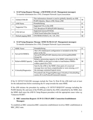
- 1. 1. S1AP Setup Request Message : eNBMME (S1AP- Management messages) To transfer information for a TNL (Transport Network Layer) association 1 Global-ENB-ID 2 eNB Name 3 Supported TAs 4 CSG Id List 5 Default paging DRX This information element is used to globally identify an eNB PLMN Identity, Macro eNB, Home eNB PrintableString Supported TAs in the eNB TAC,Broadcast PLMNs(PLMN Identity), Supported maxnoofCSGIds CSG(Closed Subscriber Group) Id ENUMERATED(32, 64, 128, 256) M O M M M 2. S1AP Setup Response Message :MMEeNB (S1AP- Management messages) To transfer information for a TNL (Transport Network Layer) association 1 MME Name 2 Served GUMMEIs 3 RelativeMMECapacity 4 CriticalityDiagnostics PrintableString The LTE related pool configuration is included on the first place in the list. Served PLMNs(PLMN Identity),Served GroupIDs(MME Group Id) Relative processing capacity of an MME with respect to the other MMEs in the pool in order to load-balance MMEs within a pool (0 to 255) Sent by the eNB or the MME when parts of a received message have not been comprehended or were missing, or if the message contained logical errors ProcedureCode,TriggeringMessage,Criticality,CriticalityDiag nostics-IE-List,ProtocolExtensionContainer O M M O If the S1 SETUP FAILURE messages include the Time To Wait IE the eNB shall wait at least for the indicated time before reinitiating the S1 setup towards the same MME. If the eNB initiates the procedure by sending a S1 SETUP REQUEST message including the PLMN Identity IEs and none of the PLMNs provided by the eNB is identified by the MME, then the MME shall reject the eNB S1 Setup Request procedure with the appropriate cause value e.g "Unknown PLMN". 3. RRC connection Request: UE E-UTRAN (RRC Connection Establishment Messages) To establish an RRC connection.RRC connection establishment involves SRB1 establishment at RRC_IDLE state. 1
- 2. Also used to transfer the initial NAS dedicated information/ message from the UE to E-UTRAN. UE sets the UE-Id, if upper layer provide S-TMSI-Temporary Mobile Subscriber Identity (The temporary UE identity provided by the MME which uniquely identifies the UE within the tracking area) then UE set the UE-Id as S-TMSI else UE will draw a random value and sets as UE-Id. 1 ue-Identity 2 establishmentCause 4. To identify the UE in the contention based access at RRC connection establishment s-TMSI, randomValue emergency, highPriorityAccess, mt-Access, mo-Signalling, mo-Data M M RRC Connection Setup: E-UTRAN UE (RRC Connection Establishment Messages) To establish an RRC connection setup involves SRB1 establishment at RRC_CONNECTED state. 2
- 3. MIB-Master Information Block (E UTRAN UE) Fixed schedule of 40msec RLC Mode-TM, Logical Channel: BCCH, Transport Channel: BCH, IDLE and CONNECTED Every 4 frames starting from SFN 0, SFN 4, SFN 8, SFN 12, SFN 16 (SFN mod 4) A limited number of most essential and most frequently transmitted parameters that are needed acquire other information from the cell. The MIB contains 1. DL bandwidth of the cell-n6, n15, n25, n50, n75, n100 (6 RB,15RB etc) 2. PHICH configuration a. PHICH-Duration-Normal, Extended b. PHICH-Resource-1/6,1/2,1,2 3. System Frame Number (SFN) 3
- 4. SIB1-System Information Block 1 (E UTRAN UE) Fixed schedule of 80msec RLC Mode-TM, Logical Channel: BCCH, Transport Channel: CONNECTED DL-SCH, IDLE and Every 8 frames starting from SFN 0, SFN 8, SFN 16 (SFN mod 8) Contains information relevant when evaluating if a UE is allowed to access a cell and defines the scheduling of other system information The SIB1 contains 1. CellAccessRelatedInfo a. PLMN-IdentityList- List of PLMN identities. The first listed PLMN-Identity is the primary PLMN b. TrackingAreaCode- A trackingAreaCode that is common for all the PLMNs listed c. CellIdentity- Identity of the cell d. CellBarred- 'barred’ means the cell is barred e. IntraFreqReselection- Used to control cell reselection to intra-frequency cells when the highest ranked cell is barred, or treated as barred by the UE f. csg-Indication- If set to TRUE the UE is only allowed to access the cell if the CSG identity matches an entry in the allowed CSG list that the UE has stored. g. csg-Identity- Identity of the Closed Subscriber Group within the primary PLMN the cell belongs to. This field is present in a CSG cell 2. cellSelectionInfo a. Q-RxLevMin b. q-RxLevMinOffset 3. p-Max- Maximum power value applicable for the cell. If this IE is absent, then the UE applies the maximum power according to the UE capability 4. freqBandIndicator- Operating frequency band of the cell 5. schedulingInfoList a. si-Periodicity- Periodicity of the SI-message in radio frames, such that rf8 denotes 8 radio frames, rf16 denotes 16 radio frames, and so on b. sib-MappingInfo- List of the SIBs mapped to this System Information message. There is no mapping information of SIB2; it is always present in the first System Information message listed in the schedulingInfoList list 6. tdd-Config-Present for only TDD if present for FDD UE shall delete this value 7. si-WindowLength- Common SI scheduling window for all SIs. Unit in milliseconds, where ms1 denotes 1 millisecond, ms2 denotes 2 milliseconds and so on. 8. systemInfoValueTag- Common for all SIBs other than MIB, SIB1, SIB10, SIB11 and SIB12. Change of MIB and SIB1 is detected by acquisition of the corresponding message 4
- 5. 5
- 6. SIB 2-System Information Block 2 (E UTRAN UE) Determine by 1st SI-160msec RLC Mode-TM, Logical Channel: BCCH, Transport Channel: CONNECTED DL-SCH, IDLE and Contains radio resource configuration information that is common for all UEs The SIB2 contains 1. ac-BarringInfo(Access Class) a. Emergency b. Mobile originating Signaling c. Mobile originating Data 2. RadioResourceConfigCommonSIB- The IE RadioResourceConfigCommonSIB is used to specify common radio resource configurations e.g., the random access parameters and the static physical layer parameters 3. UE-TimersAndConstants a. T300- RRCConnectionRequest-> RRCConnectionSetup or RRCConnectionReject b. T301- RRCConnectionReestabilshmentRequest-> RRCConnectionReestablishment or RRCConnectionReestablishmentReject and Goes to RRC_IDLE State c. T302- RRCConnectionReject-> RRC_CONNECTED and upon cell re-selection d. T303- Access barred while performing RRC connection establishment for mobile originating calls-> RRC_CONNECTED and upon cell re-selection e. T304- RRCConnectionReconfiguration-> successful completion of handover to EUTRA f. T305- RRC connection establishment for mobile originating signaling-> RRC_CONNECTED and upon cell re-selection g. T310- Upon detecting physical layer problems-> receiving N311 consecutive insync indications from lower layers h. T311- Initiating the RRC connection re-establishment procedure-> Selection of a suitable E-UTRA cell or a cell using another RAT i. T320- upon cell (re)selection to E-UTRA from another RAT with validity time configured for dedicated priorities-> RRC_CONNECTED, when PLMN selection is performed on request by NAS, or upon cell (re)selection to another RAT j. T321- Upon receiving measConfig including a reportConfig with the purpose set to reportCGI-> Upon acquiring the information needed to set all fields of cellGlobalId for the requested cell k. N310 Maximum number of consecutive "out-of-sync" indications received from lower layers l. N311 Maximum number of consecutive "in-sync" indications received from lower layers 6
- 7. 4. freqInfo a. ul-CarrierFreq b. ul-Bandwidth 5. MBSFN-SubframeConfigList 6. TimeAlignmentTimer Channels in LTE In order to carry information from one layer to other, or, from one entity to other entity. This is applicable to the Protocol stack or between UE and eNB. The Protocol Stack of UE and the associated channels are mentioned below: 7
- 8. UE Protocol Stack RLC uses Logical channels to transfer information to the MAC and lower layers; similarly, the MAC layer uses the Logical channels to transfer information to RLC and upper layers. MAC uses Transport channels to transfer information to the PHY and lower layers; similarly, the PHY layer uses the Transport channels to transfer information to MAC and upper layers. The PHY layer uses the Physical Channels in order to transfer information on the Air Interface. All the above channels have Downlink and Unlink purposes; which means that when the information is being transferred from the eNB to UE Downlink Channels are used. Similarily, Uplink channels are used when information is passed from UE to eNB. 8
- 9. The below table lists the LTE channels for DL and UL: Physical DL Channels Physical broadcast channel (PBCH) Physical control format indicator channel (PCFICH) Physical downlink control channel (PDCCH) Physical downlink shared channel (PDSCH) Physical multicast channel (PMCH) Physical Hybrid ARQ Indicator Channel (PHICH) Physical UL Channels Physical uplink control channel (PUCCH) Physical uplink shared channel (PUSCH) Physical random access channel (PRACH) Transport DL Channels Broadcast Channel (BCH) Downlink Shared Channel (DL-SCH) Paging Channel (PCH) Multicast Channel (MCH) Transport UL Channels Uplink Shared Channel (UL-SCH) Random Access Channel(s) (RACH) Logical Control Channels Broadcast Control Channel Paging Control Channel Common Control Channel Multicast Control Channel Dedicated Control Channel (DCCH) Logical Traffic Channels (BCCH) Dedicated Traffic Channel (DTCH) (PCCH) Multicast Traffic Channel (MTCH) (CCCH) (MCCH) Downlink Channels The below diagram depicts the association of LTE Downlink Channels: 9
- 10. LTE Downlink Channels Each channel has a specific role to play and the functions of each channel are mentioned below: 1. Downlink Logical Channels: a. b. c. d. e. f. g. PCCH: used for paging the UE BCCH: Used for broadcasting MIBs/SIBs CCCH: Common to multiple UE's DCCH: used to transmit dedicated control information for a particular UE DTCH: Dedicated Traffic for a particular UE MCCH: used for transmit information for Multicast reception MTCH: used to transmit Multicast data 2. Downlink Transport Channels: a. PCH: used for Paging b. BCH: used for MIB, get mapped to BCCH c. DL-SCH: used for SIB, data transfer d. MCH: used for transmitting MCCH information to set up multicast transmissions 3. Downlink Physical Channels: a. PBCH: used for transmitting MIB 10
- 11. b. PDSCH: for SIB, data c. PMCH: Multicast channel d. PHICH: for HARQ ack/nack status e. PDCCH: control channel (carries information to UE about the scheduling of PDSCH), UL grant, Indication for paging, carries HARQ ACK/NACK Uplink Channels The below diagram depicts the association of LTE Uplink Channels: LTE Uplink Channels 1. Uplink Transport Channels: a. b. RACH: used for the initial access to the network (RANDOM ACCESS Procedure) UL-SCH: used for UL data transfer 2. Uplink Physical Channels: a. b. c. PRACH: transmit RACH PUSCH: used for UL data PUCCH: used for control signaling requirements (SRs, HARQ) 11
- 12. L1-DL Control elements: 1. DCI- Downlink Control Indicator a. Which resource block carries data, what kind of demodulation scheme we have to use to decode data? b. Carried by PDCCH. c. The following formats will be used. Format 0 UL Grant. (Resource Allocation for PUSCH) Format 1 Transmission of PDSCH for SIMO operation Format 1A Resource Allocation for SIMO DL PDSCH and UL Power Control Format 1B Transmission control information of MIMO Rank 1 based compact resource assignment Format 1C Very compact type of resource allocation for PDSCH Format 1D Same as format 1B with additional information of power offset Format 2 DL MIMO Closed Loop and UL Power Control Format 2A DL MIMO Open Loop and UL Power Control Format 3 UL Power Control Only (for multiple UEs) Format 3A UL Power Control Only (for multiple UEs) 2. CFI- Control Format Indicator a. How many OFDM symbols are used for carrying PDCCH at each subframe b. Carried by PCFICH 1. CFI1 2. CFI2 3. CFI3 4. CFI4 -Reserved 3. HI-HARQ Indicator a. HARQ indicator is used indicate a positive acknowledgement (ACK) or negative acknowledgement (NACK) for data sent using the uplink shared channel. b. Carried by PHICH 1. HI= ‘0' represents a NACK 2. HI=‘1' represents an ACK. L1-UL Control elements: 1. CQI- Channel Quality Indicator a. Carrying the information on how good/bad the communication channel quality 12
- 13. b. The following factors will be used for calculating the Channel quality. 1. signal-to-noise ratio (SNR) 2. signal-to-interference plus noise ratio (SINR) 3. signal-to-noise plus distortion ratio (SNDR) c. CQI is carried by PUCCH or PUSCH depending on the situation as follows. 1. Carried by PUCCH : When there is no uplink data to be transmitted 2. Carried by PUSCH: When there is uplink data to be transmitted. d. The following tables mapping of 4-bit CQI with Modulation. 2. SR- Scheduling Request a. Scheduling radio resource for uplink transmission by the UE to the Enb b. UE send SR on PUCCH when regular BSR (Buffer status report) is triggered and UE does not have radio resource to transmit this BSR to eNB. c. Carried by PUCCH 3. HI- HARQ Indicator d. HARQ indicator is used indicate a positive acknowledgement (ACK) or negative acknowledgement (NACK) for data sent using the downlink shared channel. e. Carried by PUCCH 1. HI= ‘0' represents a NACK 2. HI=‘1' represents an ACK. 13