

Recommandé
Recommandé
Contenu connexe
Tendances
Tendances (20)
Similaire à Fvr e11 manual
Similaire à Fvr e11 manual (20)
Plus de Toàn Huỳnh
Plus de Toàn Huỳnh (20)
Dernier
Dernier (20)
Fvr e11 manual
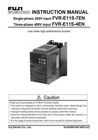
- 1. INSTRUCTION MANUAL Single-phase 200V input FVR-E11S-7EN Three-phase 400V input FVR-E11S-4EN Low noise high performance inverter Caution Thank you for purchasing our FVR-E11S series inverter. • This product is designed to drive a three-phase induction motor. Read through this instruction manual and be familiar with the handling method for correct use. • Improper handling blocks correct operation or causes a short life or failure. • Have this manual delivered to the final user of the product. Keep this manual in a safe place until the inverter is discarded. • For the usage of optional equipment, refer to the manuals for optional equipment. Fuji Electric Co., Ltd. Draft(INR-SI47-0627a-E)
- 2. i Introduction Safety precautions Read through this manual before starting installation, connection (wiring), operation, or maintenance and inspection for correct use. Be familiar with the knowledge about the device, information about safety, and all the precautions before starting operation. The safety precautions are classified into the following categories in this manual. !!!! WARNING Negligence of the description can cause dangers including deaths or serious injuries. !!!! CAUTION Negligence of the description can cause dangers including intermediate or slight injuries or material losses. Negligence of the description under the CAUTION title can cause serious results in certain circumstances. These safety precautions are important and must be observed at any time. Purposes !!!! WARNING • FVR-E11S is designed to drive a three-phase induction motor. Do not use it for single-phase motors or for other purposes. Otherwise fire could occur. • FVR-E11S may not be used for a life-support system or other purposes directly related to the human safety. • Though FVR-E11S is manufactured under strict quality control, install safety devices for applications where serious accidents or material losses are foreseen in relation to the failure of it. Otherwise an accident could occur. Installation !!!! WARNING • Install the inverter on a nonflammable material such as metal. Otherwise fire could occur. • Do not place flammable matter nearby. Otherwise fire could occur. !!!! CAUTION • Do not hold the cover during transportation. Otherwise the inverter may drop and cause injuries. • Do not allow lint, paper, wood chips, dust, metallic chips or other foreign matter in the inverter or do not allow them attached to the heat sink. Otherwise fire or an accident could occur. • Do not install or operate an inverter which is damaged or lacking parts. Otherwise fire, an accident or injuries could occur. Wiring !!!! WARNING • When connecting the inverter to the power supply, add a circuit breaker for circuit protection and earth leakage breaker in the path of power supply. Otherwise fire could occur. • Be sure to connect the grounding cable without fail. Otherwise electric shock or fire could occur. • Both screws of grounding terminals of FVR5.5/7.5E11S-4EN has to be tightened up securely even if one grounding terminal is not used. Otherwise electric shock or fire could occur. • Qualified electricians should carry out wiring. Otherwise electric shock could occur. • Perform wiring after checking that the power supply is turned off. Otherwise electric shock could occur. • Be sure to perform wiring after installing the main body of the inverter. Otherwise electric shock or injuries could occur.
- 3. ii !!!! CAUTION • Check that the number of phases and the rated voltage of the product agree with the number of phases and the voltage of the AC power supply. Otherwise fire or an accident could occur. • Do not connect the AC power cables to the output terminals (U, V, W). Otherwise fire or an accident could occur. • Do not connect a braking resistor directly to the DC terminals (P (+), N (-)). Otherwise fire or an accident could occur. • The inverter, motor and wiring generate electric noise. Take care of malfunction of the nearby sensors and devices. Otherwise an accident could occur. Operation !!!! WARNING • Be sure to install the terminal cover before turning the power on. Do not remove the cover during power application. Otherwise electric shock could occur. • Do not operate switches with wet hands. Otherwise electric shock could occur. • If the retry function has been selected, the inverter may automatically restart according to some causes after tripping. (Design the machine so that human safety is ensured after restarting.) Otherwise an accident could occur. • If the torque limit function has been selected, the inverter may operate at an acceleration/deceleration time or speed different from the set ones. Design the machine so that safety is ensured even in such cases. Otherwise an accident could occur. • The STOP key is only effective when function setting has been established to make the STOP key enable. Prepare an emergency stop switch separately. Otherwise an accident could occur. • If an alarm reset is made with the operation signal turned on, a sudden start will occur. Check that the operation signal is turned off in advance. Otherwise an accident could occur. • Do not touch the inverter terminals during power applies to the inverter even if the inverter stops. Otherwise electric shock could occur. !!!! CAUTION • Do not turn the main circuit power on or off to start or stop inverter operation. Otherwise failure could occur. • Do not touch the heat sink and braking resistor because they become very hot. Otherwise burns could occur. • Setting the inverter to high speeds is easy. Check the performance of the motor and machines before changing the setting. Otherwise injuries could occur. • The brake function of the inverter does not provide mechanical holding means. Injuries could occur.
- 4. iii Maintenance and inspection and parts replacement !!!! WARNING • Turn the power off and wait for at least five minutes before starting inspection. (Further, check that the charge lamp is unlit, and check the DC voltage across the P (+) and N (-) terminals to be lower than 25Vdc.) Otherwise electric shock could occur. • Maintenance and inspection and parts replacement should be made only by qualified persons. (Take off the watch, rings and other metallic matter before starting work.) (Use insulated tools.) Otherwise electric shock or injuries could occur. Disposal !!!! CAUTION • Handle the inverter as an industrial waste when disposing of it. Otherwise injuries could occur. Others !!!! WARNING • Never remodel. Otherwise electric shock or injuries could occur. GENERAL PRECAUTIONS Drawings in this manual may be illustrated without covers or safety shields for explanation of detail parts. Restore the covers and shields in the original state and observe the description in the manual before starting operation.
- 5. iv Conformity to Low Voltage Directive in EU [Available only for the products with CE or TÜV mark] !!!! CAUTION 1. Safe separation for control interface of this inverter is provided when this inverter is installed in overvoltage category II. PELV(Protective Extra Low Voltage) circuit or SELV(Safety Extra Low Voltage) circuit from external controller is connected to the interface directly. 2. Basic insulation for control interface of this inverter is provided when this inverter is installed in overvoltage category III. An insulation transformer has to be installed between power supply mains and this inverter when SELV circuit from external controller is connected to this inverter directly. Otherwise supplementary insulation between control interface of this inverter and environment must be provided. 3. The ground terminal G should always be connected to the ground. Don't use only RCD as the sole method of electric shock protection. Dimensions of external PE conductor should be same as dimensions of input phase conductor and capable for possible fault. 4. Use MCCB or MC that conforms to EN or IEC standard. 5. Where RCD (Residual-current-operated protective device) is used for protection in case of direct or indirect contact, only RCD of type B is allowed on the supply side of this EE (Electric equipment). Otherwise another protective measure shall be applied such as separation of the EE from the environment by double or reinforced insulation or isolation of EE and supply system by the transformer. 6. The inverter has to be installed in environment of pollution degree 2. If the environment is pollution degree 3 or 4, the inverter has to be installed in a cabinet of IP54 or higher. 7. Use a prescribed wire according to the EN60204 Appendix C. 8. Install the inverter, AC or DC reactor, input or output filter in an enclosure that meets the following requirement, to prevent a human body from touching directly to these equipment. 1) When a person can touch easily on each connecting terminal or live parts, install the inverter, AC or DC reactor, output filter in an enclosure with minimum degree of protection of IP4X. 2) When a person can not touch easily on each connecting terminal or live parts, install the inverter, AC or DC reactor, output filter in an enclosure with a minimum degree of protection of IP2X. 9. It is necessary to install the inverter in appropriate method using an appropriate RFI filter to conform to the EMC directive. It is customer's responsibility to check whether the equipment ,the inverter is installed in, conforms to EMC directive. 10. Do not connect copper wire to grounding terminal directly. Use cramp terminal with tin or equivalent plating to reduce electrochemical potential. 11. Do not remove the keypad panel before disconnecting power and do not insert/remove the extension cable for keypad panel remote operation while power is on. Confirm that the extension cable is securely latched to keypad panel and inverter before power is on. A supplementary isolation is required for the extension cable when the inverter is installed in overvoltage category III. 12. Basic insulation for control interface of this inverter is provided when the inverter is used at altitude over 2000m. The use at altitude over 3000m is not permitted. 13. The supply mains neutral has to be earthed for FVR-E11S-4EN.
- 6. v Caution for UL/cUL requirement [Available only for the products with UL/cUL mark] !!!! CAUTION 1. [WARNING] Take care of electric shock. Be sure to turn the inverter off before starting work. 2. [CAUTION] When the charge lamp is lit, the inverter is still charged at a dangerous voltage. 3. [WARNING] There are two or more live parts inside the inverter. 4. The inverter is approved as a part used inside a panel. Install it inside a panel. 5. Perform wiring to the input, output and control terminals of the inverter, referring to the table below. Use UL certified round crimp terminal to the input and output terminals with insulation cover or covered with reduced tube to obtain the insulation distance. Use a crimping tool recommended by the terminal manufacturer when fabricating crimp terminals. 6. Install a fuse or circuit breaker between the power supply and the inverter, referring to the table below. 1) Use copper wires of allowable maximum temperature 60 or 75 degree C. 2) Use UL certified AC600V "Class J fuse." 7. The inverters FVR0.1 to 2.2E11S-7 are suitable for use on a circuit capable or delivering not more than 20,000 rms symmetrical amperes, 240V maximum. 8. The inverters FVR0.4 to 7.5E11S-4 are suitable for use on a circuit capable or delivering not more than the following symmetrical amperes, 480V maximum. When the fuse is installed : 20,000A When the circuit breaker is installed : 5000A 9. FVR-E11S-EN is an open type inverter. 10. A class 2 circuit wired with class 1 wire. Tightening torque [N·m] Applicable wire diameter [AWG] (mm 2 ) 1) Inverter type L1/R,L2/S, L3/T L1/L, L2/N P1,P(+) DB,N(-) U, V, W Control section L1/R,L2/S, L3/T L1/L, L2/N G P1,P(+) DB,N(-) U, V, W Control section Fuse 2) [A] Breaker[A] FVR0.1E11S-7EN 6 5 FVR0.2E11S-7EN 6 5 FVR0.4E11S-7EN 1.2 10 10 FVR0.75E11S-7EN 14 (2.1) 15 15 FVR1.5E11S-7EN 12 (3.3) 30 30 FVR2.2E11S-7EN 1.8 0.4 10 (5.3) 20 (0.5) 40 40 FVR0.4E11S-4EN FVR0.75E11S-4EN 6 5 FVR1.5E11S-4EN 10 10 FVR2.2E11S-4EN 15 15 FVR4.0E11S-4EN 1.8 14 (2.1) 20 20 FVR5.5E11S-4EN 12 (3.3) 30 30 FVR7.5E11S-4EN 3.5 0.4 10 (5.3) 20 (0.5) 40 40
- 7. Contents 1. Before Using the Inverter・・・・・・・・・・・・・・・・・・・・・・・・・・・・・・・・・・・・・・・・・・・・・・・・・・・・ 1-1 1-1 Receiving Inspection ・・・・・・・・・・・・・・ 1-1 1-2 Appearance of Product ・・・・・・・・・・・・ 1-1 1-3 Handling the Product ・・・・・・・・・・・・・・ 1-3 1-4 Transportation ・・・・・・・・・・・・・・・・・・・・ 1-6 1-5 Storage・・・・・・・・・・・・・・・・・・・・・・・・・・ 1-6 2. Installation and Connection ・・・・・・・・・・・・・・・・・・・・・・・・・・・・・・・・・・・・・・・・ 2-1 2-1 Operating Environment ・・・・・・・・・・・・ 2-1 2-2 Installation Method ・・・・・・・・・・・・・・・・ 2-1 2-3 Connection・・・・・・・・・・・・・・・・・・・・・・・ 2-2 2-3-1 Basic Connection・・・・・・・・・・・・・・・ 2-2 2-3-2 Connection of Main Circuit and Grounding Terminal・・・・・・・・・・・・・ 2-4 2-3-3 Connection of Control Terminal・・・ 2-6 2-3-4 Terminal Layout ・・・・・・・・・・・・・・・・ 2-9 2-3-5 Applicable Devices and Cable Sizes for Main Circuit ・・・・・・ 2-11 3. Operation・・・・・・・・・・・・・・・・・・・・・・・・・・・・・・・・・・・・・・・・・・・・・・・・・・・・・・・・・・・・・・・・・・・・・・・・・・・・・・・・・・・・・・・・・・・・・・・・・・・・・・・・・・・・ 3-1 3-1 Inspection and Preparation Before Operation・・・・・・・・・・・・・・・・・・ 3-1 3-2 Operation Method・・・・・・・・・・・・・・・・・ 3-1 3-3 Test Operation・・・・・・・・・・・・・・・・・・・・ 3-1 4. Keypad Panel ・・・・・・・・・・・・・・・・・・・・・・・・・・・・・・・・・・・・・・・・・・・・・・・・・・・・・・・・・・・・・・・・・・・・・・・・・・・・・・・・・・・・・・・・・・・・ 4-1 4-1 Appearance of Keypad Panel・・・・・・・ 4-1 4-1-1 Upon an Alarm ・・・・・・・・・・・・・・・・・ 4-3 4-1-2 Digital Frequency Setting Method ・ 4-3 5. Selecting Functions ・・・・・・・・・・・・・・・・・・・・・・・・・・・・・・・・・・・・・・・・・・・・・・・・・・・・・・・・・・・・・・・・・・・・ 5-1 5-1 Function Selection List・・・・・・・・・・・・・ 5-1 5-2 Detail Description of Each Function ・ 5-11 Fundamental Functions (F Functions) ・・・ 5-11 Extension Terminal Functions (E Functions) ・・・・・・・・・・・・・・・・・・・・・・・・・・・・・・ 5-21 Control Functions of Frequency (C Functions) ・・・・・・・・・・・・・・・・・・・・・・・・ 5-26 Motor Parameters (P Functions) ・・・・・・・・ 5-29 High Performance Functions (H Functions) 5-31 Alternative Motor Parameters (A Functions) ・・・・・・・・・・・・・・・・・・・・・・・・・・・・・・ 5-39 Optional Functions(O Functions)・・・・・・・・ 5-40 6. Protective Operation ・・・・・・・・・・・・・・・・・・・・・・・・・・・・・・・・・・・・・・・・・・・・・・・・・・・・・・・・・・・・・・・・・・・・ 6-1 6-1 List of Protective Operations・・・・・・・・ 6-1 6-2 Alarm Reset・・・・・・・・・・・・・・・・・・・・・・ 6-2 7. Troubleshooting・・・・・・・・・・・・・・・・・・・・・・・・・・・・・・・・・・・・・・・・・・・・・・・・・・・・・・・・・・・・・・・・・・・・・・・・・・・・・・・・・・・・7-1 7-1 When Protective Function Goes Active ・・・・・・・・・・・・・・・・・・・・・・・・・・・ 7-1 7-2 When Motor rotates Incorrectly ・・・・・・・ 7-5 8. Maintenance and Inspection ・・・・・・・・・・・・・・・・・・・・・・・・・・・・・・・・・・・・・・・・8-1 8-1 Daily Inspection・・・・・・・・・・・・・・・・・・・ 8-1 8-2 Periodic Inspection ・・・・・・・・・・・・・・・・ 8-1 8-3 Measurement of Electrical Amounts in Main Circuit ・・・・・・・・・・・・・・・・・・・・ 8-4 8-4 Insulation Test ・・・・・・・・・・・・・・・・・・・・ 8-5 8-5 Replacement Parts ・・・・・・・・・・・・・・・・ 8-5 8-6 Inquiries about Product and Guarantee ・・・・・・・・・・・・・・・・・・・・・・・ 8-5 9. Specifications ・・・・・・・・・・・・・・・・・・・・・・・・・・・・・・・・・・・・・・・・・・・・・・・・・・・・・・・・・・・・・・・・・・・・・・・・・・・・・・・・・・・・・・・・・・・・9-1 9-1 Standard Specifications ・・・・・・・・・・・・ 9-1 9-2 Common Specifications・・・・・・・・・・・・ 9-3 9-3 External Dimensions ・・・・・・・・・・・・・・ 9-7 9-4 RS485 Communication ・・・・・・・・・・・・ 9-11 9-4-1 Connector and Communication Cable ・・・・・・・・・・・・・・・・・・・・・・・・・・9-12 9-4-2 Recommended RS-232C/RS485 Converter ・・・・・・・・・・・・・・・・・・・・・・9-12 9-4-3 Remove/local changeover ・・・・・・・・9-12 9-4-4 Communication Protocol ・・・・・・・・・9-13 9-4-5 Standard Frame・・・・・・・・・・・・・・・・・9-15 9-4-6 Short Frame ・・・・・・・・・・・・・・・・・・・・9-16 9-4-7 Details of Frame ・・・・・・・・・・・・・・・・9-17 9-4-8 Broadcasting ・・・・・・・・・・・・・・・・・・・9-18 9-4-9 Communication Error Code ・・・・・・・9-19 9-4-10Data Type ・・・・・・・・・・・・・・・・・・・・・・9-19 9-4-11Function Code List・・・・・・・・・・・・・・・9-20 9-4-12Data Format ・・・・・・・・・・・・・・・・・・・・9-24 10. Options ・・・・・・・・・・・・・・・・・・・・・・・・・・・・・・・・・・・・・・・・・・・・・・・・・・・・・・・・・・・・・・・・・・・・・・・・・・・・・・・・・・・・・・・・・・・・・・・・・・・・・・・・・・・・・・・・10-1 10-1 External Options ・・・・・・・・・・・・・・・・・ 10-1 11. Applicable Reactor ・・・・・・・・・・・・・・・・・・・・・・・・・・・・・・・・・・・・・・・・・・・・・・・・・・・・・・・・・・・・・・・・・・・・11-1 12. Electromagnetic compatibility・・・・・・・・・・・・・・・・・・・・・・・・・・・・12-1 12-1General・・・・・・・・・・・・・・・・・・・・・・・・・・ 12-1 12-2 Recommended Installation Instructions ・・・・・・・・・・・・・・・・・・・・・・・・・・・・・・・・・ 12-1
- 8. 1-1 1. Before Using the Inverter 1-1 Receiving Inspection Unpack and check the following items. If you have any problems with the product, contact the dealer or the nearest branch of Fuji Electric Co., Ltd. (1) Check the ratings nameplate to confirm that the delivered product is the ordered one. TYPE: Type of inverter FVR 0.4 E11S -7 EN Version Power voltage system: 7: Single-phase 200V class 4: Three-phase 400V class Series name: E11S Nominal applicable motor capacity: 0.4: 0.4 kW Product type SOURCE: Number of input phases, input voltage, input frequency, input current OUTPUT: Number of output phases, rated output capacity, rated output voltage, output frequency range, rated output current, overload current rating SER. NO.: Product number 0 1 0113R0001 Serial number of production lot Production month: 1 to 9: January to September; X, Y, or Z: October, November, or December Production year: Last digit of year (2) Check for breakage, missing parts, and dents or other damage on the cover and the main body given during transportation. (3) Instruction manual for inverter body is built-in. 1-2 External view of Product (1-1) Overall view (4.0kW or below) Keypad panel Control terminal block cover Intermediate cover Ratings nameplate Main circuit terminal block cover Keypad panel mounting screw FVR0.4E11S-7EN 1PH 200-240V 50/60Hz 6.4A 3PH 0.4kW 200-230V 0.2-400Hz 3.0A 150% 1min 010113R0001 T
- 9. 1-2 (1-2) Overall view (5.5,7.5kW) (2-1) View of wiring part(4.0kW or below) A barrier is provided in the main circuit terminal block cover for the P1, P (+), DB and N (-) cable port. Cut the barrier using nippers or the like before wiring. Keypad panel Control cable port Terminal block cover P1, P (+), DB, N (-) cable port Intermediate cover L1/R, L2/S, L3/T (L1/L, L2/N), U, V, W cable port Ratings nameplate Grounding cable port Keypad panel mounting screw
- 10. 1-3 (2-2) View of wiring part(5.5,7.5kW) A barrier is provided in the cable cover for the P1, P (+), DB and N (-) cable port. Cut the barrier using nippers or the like before wiring. 1-3 Handling the Product (1) Removing the control terminal block cover(4.0kW or below) While lightly pushing the sides of the control terminal block cover at the catches, lift the cover in the procedure shown in Fig. 1-3-1 to remove it. Fig. 1-3-1 Removing the control terminal block cover Control cable port P1, P (+), DB, N (-) cable port L1/R, L2/S, L3/T cable port Grounding cable port U, V, W cable port Cable cover Terminal block cover
- 11. 1-4 (2) Removing the main circuit terminal block cover(4.0kW or below) While lightly pushing the sides of the main circuit terminal block cover at the catches, slide toward you in the procedure shown in Fig. 1-3-2 to remove it. Fig. 1-3-2 Removing the main circuit terminal block cover (3) Removing the terminal block cover(5.5,7.5kW ) Loose the screws indicated below and while lightly pushing the sides of the terminal block cover at the catches, lift the cover in the procedure shown in Fig. 1-3-3 to remove it. ①①①① ①①①① ②②②② ②②②② ③③③③ Fig. 1-3-3 Removing the terminal block cover screws
- 12. 1-5 (4) Removing the keypad panel Loosen the keypad panel mounting screws and remove the keypad panel in the procedure shown in Fig. 1-3-4. During the procedure, slowly remove the keypad panel right toward the top. If the keypad panel is handled abruptly, the connector will be broken. Mounting screw (M3) Fig. 1-3-4 Removing the keypad panel Reverse the procedures to mount the terminal block cover and keypad panel.
- 13. 1-6 1-4 Transportation Always hold the main unit when carrying the inverter. If covers or parts are held, the inverter may be broken or it may drop. 1-5 Storage Store the inverter in an environment described in Table 1-5-1. Table 1-5-1 Storage environment Item Specifications Ambient temperature -10~+50 degree C Storage temperature (Note 1) -25~+65 degree C Relative humidity 5~95%Note 2 Places not subjected to abrupt temperature changes or condensation or freezing Atmosphere The product must not be exposed to dust, direct sunlight, corrosive or flammable gases, oil mist, vapor, water drops or vibration. There must be little salt in the atmosphere. 86~106kPa (During storage) Atmospheric pressure 70~106kPa (During transportation) Note 1: The storage temperature is for a short time during transportation or the like. Note 2: Even if the humidity is within the requirements of the specifications, places with abrupt temperature changes are subject to condensation or freezing. Avoid storing the inverter in such places. (1) Do not place the inverter directly on the floor. (2) If the ambient atmosphere is adverse, wrap the inverter in a vinyl sheet or the like when storing. (3) If humidity may give an ill effect, add a drying agent (such as silica gel) in the package prepared as described in item (2). The long-term storage method of the inverter varies largely according to the environment of the storage site. General storage methods are described below. (1) The storage site must satisfy the requirements of specifications for temporary storage. However, for storage exceeding three months, the upper limit of the ambient temperature shall not exceed 30 °C. This is for the prevention of deterioration of electrolytic capacitors left turned off. (2) The package must be air tight so that moisture will not enter. Add a drying agent inside the package to contain the relative humidity inside the package within 70%. (3) The inverter installed on a unit or control panel and left is likely to be exposed to moisture and dust. If this is the case, remove the inverter and move it to a preferable environment. (4) Electrolytic capacitors left turned off for an extended period of time deteriorate. Do not store for one year or more without turning the power on. To store temporarily To store for a long time
- 14. 2-1 2. Installation and Connection 2-1 Operating Environment Install the inverter in an environment described in Table 2-1-1. Table 2-1-1 Operating environment Item Specifications Site Indoors Ambient temperature -10 to +50 degree C Relative humidity 5 to 95% (without condensation) Atmosphere The inverter must not be exposed to dust, direct sunlight, corrosive gases, oil mist, vapor or water drops. There must be little salt. No condensation occurs due to abrupt temperature changes. Altitude 1,000 m max. (Refer to Table 2-1-2 for altitudes exceeding 1000 m.) Atmospheric pressure 86 to 106 kPa 3mm 2 to 9 Hz 9.8m/s 2 9 to 20 Hz 2m/s 2 20 to 55 Hz Vibration 1m/s 2 55 to 200 Hz 2-2 Installation Method (1) Tightly mount the inverter in the upright position on a rigid structure so that the "FVR-E11" characters face front. Avoid mounting the inverter upside down or avoid mounting horizontally. (2) Allow clearances for cooling wind shown in Fig. 2-2-1 to cool down the inverter which generates heat during operation. The generated heat is radiated upward. Do not install the inverter below a heat sensitive device. (3) The temperature of the heat sink rises to about 90 degrees C during operation of the inverter. Mount the inverter on a base made of a material withstanding the temperature rise. !!!! WARNING Install the inverter on a nonflammable material such as metal. Otherwise fire could occur. (4) When installing the inverter inside a control panel or the like, take full consideration for ventilation so that the ambient temperature of the inverter does not exceed the specification requirements. Do not install the inverter in a poorly ventilated small enclosure. (5) When storing multiple inverters inside a single unit or inside a control panel, horizontal installation is recommended to reduce mutual temperature effects. When an vertical layout is adopted for an unavoidable reason, install a partition plate or the like between inverters to isolate the heat of the lower inverter. !!!! CAUTION Do not allow lint, paper, wood chips, dust, metallic chips or other foreign matter in the inverter or do not allow them attached to the heat sink. Otherwise fire or an accident could occur. Fig. 2-2-1 Table 2-1-2 Output attenuation ratio in relation to altitude Altitude Output current attenuation ratio 1000 m or less 1.00 1000-1500m 0.97 1500-2000m 0.95 2000-2500m 0.91 2500-3000m 0.88 Above Main body FVR-E11S10mm 100mm Below Left 10mm 100mm Right
- 15. 2-2 2-3 Connection Remove the control terminal block cover to connect the control terminal block. Remove the main circuit terminal block cover to connect the main circuit terminal block. Correctly connect cables taking care of the following precautions. 2-3-1 Basic Connection (1) Be sure to connect the power cables to main circuit power terminals L1/R, L2/S and L3/T or L1/L,L2/N of the inverter. If the power cables are connected to other terminals, the inverter will be broken. As well, check the source voltage for the allowable voltage range specified on the nameplate and so on. (2) Connect the grounding terminal without fail according to national or local electric code to prevent electric shock, fire or other disasters and to reduce electric noise. (3) Use reliable crimp terminals for connection of cables to the terminals. (4) After finishing wiring, check the following. a. Check if the cables are connected correctly. b. Check if there is no failure of connection. c. Check if terminals or cables are short circuited or there is a ground fault. (5) To change connection of an inverter having been turned on The smoothing capacitor in the direct current part of the main circuit takes time to be discharged after it is turned off. To avoid danger, check the DC voltage (across main circuit terminals P (+) and N (-)) for a safety voltage (25 Vdc or lower) using a multi-meter, after the charge lamp is unlit. Wait until the residual voltage is discharged before shorting a circuit, to avoid being hit by sparks caused by the voltage (electric charge). !!!! WARNING • Be sure to connect the grounding cable without fail. Otherwise electric shock or fire could occur. • Qualified electricians should carry out wiring. Otherwise electric shock could occur. • Perform wiring after checking that the power supply is turned off. Otherwise electric shock could occur.
- 16. 2-3 ■■■■ Basic connection diagram U L2/N L1/L Power supply (*1) Single-phase 200 to 240 V 50/60 Hz Molded case circuit breaker (MCCB) or earth leakage circuit breaker (ELCB) Power supply (*1) Three-phase 380 to 480 V 50/60 Hz G EFL-E11-7 FWD REV X1 X2 X3 X4 X5 CM 13 12 11 C1 FM V W P1 P(+) DB N(-) M <Y1E> <Y2E> <CMC> G Motor Grounding terminal SR 10Vdc (-) (+) 22~27Vdc Pulse output Control circuit part Analog frequency meter 0 to 50Hz FM(*2) Current input for setting 4 to 20mAdc A voltage signal (0 to +10 Vdc or 0 to +5 Vdc) can be supplied to terminals [12] and [11] instead of a potentiometer. Potentiometer (*2) DC reactor DCR (*2) External braking resistor (*2) (*4) P DB 2 1 Transistoroutput Digitalinput(*2) Analog input Alarmrelayoutput 30 30A 30B 30C 3 2 1 Grounding terminal (P24) (THR) (*3) Digital frequency meter (pulse counter) (*2) 50Hz 22kohm FM Analog output 250ohm To change the FM terminal to pulse outputs, change SW1 on the control board and change F29. (P24) (THR) (When X5 assigned to THR) 3 P24 L1/R L3/T L2/S L N L' N' EFL-E11-4 G L1' L2' L3' 0V L1 L2 L3 (*3) Electric cabinet Armoured or screened cable EMC compliance filter (*2) EMC compliance filter (*2) CM FVR-E11S-EN CM CM SW1 *1) Supply a source voltage suitable for the rated voltage of the inverter. *2) Optional part. Use when necessary. *3) Peripheral equipment. Use when necessary. *4) To connect a DC reactor (DCR) for power factor correcting, remove the jumper between the P1 and P (+) terminals.
- 17. 2-4 2-3-2 Connection of Main Circuit and Grounding Terminal Table2-3-1 Connection of Main Circuit and Grounding Terminal Symbol Name of terminal Description L1/R,L2/S,L3/T Main circuit power input Connects a 3-phase power supply. L1/L,L2/N Main circuit power input Connects a 1-phase power supply. U,V,W Inverter output Connects a 3-phase induction motor. P1,P(+) For DC reactor Connects an optional DC reactor. P(+),DB For external braking resistor Connects an optional external braking resistor. P(+),N(-) DC link circuit terminal Connected to DC link circuit. G grounding Grounding terminal of the inverter chassis (housing). Connect to the protective ground. (1) Main circuit power input terminal (L1/R, L2/S, L3/T,L1/L,L2/N) a. Connect the main circuit power input terminals to the power supply through a circuit breaker for circuit (wiring) protection or an earth leakage breaker. There is not need to match the phase sequence. b. It is recommended to connect a magnetic contactor to disconnect the inverter from the power supply to prevent a failure or accident from becoming serious upon activation of the protective function of the inverter. c. Do not turn the main circuit power supply on or off to start or stop the inverter. Instead, use control circuit terminals FWD and REV or the RUN and STOP keys on the keypad panel. If it is unavoidable to turn the main circuit power supply on or off to start or stop the inverter, limit the frequency to once an hour or fewer. d. Do not connect to a single-phase power supply for 3-phase input inverter. (2) Inverter output terminals (U, V, W) a. Connect these terminals to a 3-phase motor with the correct phase sequence. If the direction of rotation does not match the operation direction, change arbitrary two cables among the U, V and W phases. b. Do not connect a phase advance capacitor or surge absorber to the inverter output. c. If the wiring length between the inverter and the motor is extremely long, the stray capacity between cables causes a high frequency current, possibly tripping the inverter due to an overcurrent, increasing the leakage current, or deteriorating the current detection accuracy to cause deterioration of the performance or other phenomena. To prevent such trouble, limit the wiring length of the motor to 50 m for 4.0 kW or a smaller output or to 100 m for a larger output. Note: When a thermal relay is installed in the path between the inverter and the motor, or especially in the case of a 400V system, the thermal relay may malfunction even with a wiring length shorter than 50 m. In such a case, add an OFL filter or lower the Motor sound adjustment (carrier frequency) of the inverter. ... Function code F26 Motor sound adjustment.
- 18. 2-5 (3) DC reactor connecting terminals (P1, P (+)) a. Use this terminal to connect a DC reactor (option). Remove the jumper connected in the factory before connecting the DC reactor. b. Do not remove the jumper if no DC reactor is used. Cut the barrier in the main circuit terminal block cover for the P1, P (+), DB and N (-) cable port using nippers or the like when connecting wiring. (4) External braking resistor connecting terminals (P (+), DB) E11S is not equipped with a braking resistor. An external braking resistor (option) is necessary for frequent operation or heavy duty inertia load operation to enhance the braking performance. a. Connect the P (+) and DB terminals of the external braking resistor to the P (+) and DB terminals of the inverter. b. Arrange devices so that the wiring length is within 5 m and twist or closely (in parallel) place the two cables. (5) Inverter grounding terminal ( G ) Ground the grounding terminal G for safety and noise reduction without fail. The metallic frame of electrical equipment must be grounded in accordance with national or local electric code to avoid electric shock, fire and other disasters. !!!! CAUTION • Check that the number of phases and the rated voltage of the product agrees with the number of phases and the voltage of the AC power supply. • Do not connect the AC power cables to the output terminals (U, V, W). Otherwise injuries could occur. • Do not connect a braking resistor directly to the DC terminals (P (+), N (-)). Otherwise fire could occur. P1 P(+) DB N(-) DC reactor DCR External braking resistor DB P DB 2 1 (P24) (THR) Fig. 2-3-2 Connection diagram Fig. 2-3-1 DCR connection diagram
- 19. 2-6 2-3-3 Connection of Control Terminal Table 2-3-2 shows the functions of the control circuit terminals. The method of connecting control function terminals varies according to the function setting. Refer to the connection method for the function. Table 2-3-2 Functions of control circuit terminals Classifica- tion Terminal symbol Terminal name Description of function 13 Potentiometer power supply +10 Vdc power supply for frequency setting POT. (POT: 1 to 5 kohm). 12 Voltage input (1) The frequency is set according to the external analog input voltage command. • 0 to +10 Vdc / 0 to 100% • Reversible operation using +/- signal: 0 to +/-10 Vdc / 0 to 100% • Inverse mode operation: +10 to 0 Vdc / 0 to 100% (2) The PID control feedback signal is input. * Input resistance: 22 kohm C1 Current input (1) The frequency is set according to the analog input current command. • 4 to 20 mAdc / 0 to 100% • Inverse mode operation: 20 to 4 mAdc / 0 to 100% (2) The PID control feedback signal is input. * Input resistance 250 ohm Analog input 11 Common Common for analog signals FWD Forward operation command Forward operation with FWD-P24 ON and deceleration and stop with FWD-P24 OFF. REV Reverse operation command Reverse operation with REV-P24 ON and deceleration-stop with REV-P24 OFF. X1 Digital input 1 X2 Digital input 2 X3 Digital input 3 X4 Digital input 4 X5 Digital input 5 A coast-to-stop command from an external device, external alarm, alarm reset, multi-step frequency selection and other functions can be assigned to the X1 through X5 terminals. Refer to the terminal function E01 to 05 setting method in section 5-2 Detail Description of Each Function. <Digital input circuit specification> P24 Control unit power supply +24V DC power supply for control input. Maximum output current : 50mA Digital input CM Common Common for digital input FWD,REV, X1 to X5 CM 4.7kohm P24 +24 V Item min. typ. Max. Level OFF 0V - 2VOperation voltage Level ON 22V 24V 27V Operation current at ON - 4.2mA 6mA Allowable leakage current at OFF - - 0.5mA
- 20. 2-7 Classifica- tion Terminal symbol Terminal name Description of function Analog monitor The monitor signal for analog DC voltage (0 to +10 Vdc) is output. The signal description can be selected from the following. • Output frequency1 (before slip compensation) • Output frequency2 (after slip compensation) • Output current • Output voltage • Output torque • Load factor • Input power • PID feedback value • DC link circuit voltage * Allowable connection impedance: min. 5 k ohm Analog output / pulse output FM (11: Common terminal) Pulse rate monitor The monitor signal is output according to the pulse voltage. The signal description is the same as the FMA signal. * Allowable connection impedance: min. 5 k ohm Use SW1 on the control board and function code F29 to change between the analog monitor and Pulse rate monitor. (FMA: analog monitor, FMP: Pulse rate monitor) Y1E Transistor output 1 Y2E Transistor output 2 The RUN signal, frequency equivalence signal, overload early warning signal and other signals are output to arbitrary ports at a transistor output. Refer to terminal function E20 to 21 setting methods in section 5-2 Detail Description of Each Function. <Transistor output circuit specification> CMC Common (Transistor output) Common for transistor output signal. Isolated from terminals CM and 11. Transistor output P24 (CM: common terminal) DC voltage supply Power supply for transistor output load. (24 Vdc 50 mAdc Max.) (When using P24, short the CMC and P24 terminals.) (If the P24 terminal is overloaded or connected with the CM terminal, the inverter trips with Er3 indication. To reset, remove external causes and, after several minutes, turn the inverter on again.) Relay output 30A,30 B,30C Alarm relay output When the inverter is stopped with an alarm, a relay contact output (1C) is issued. Contact capacity: 48 Vdc 0.5 A (When complying with UL/cUL:42Vdc 0.5A) Selection between excitation upon an alarm or excitation during normal operation is allowed. Item min. typ. max. ON level - 1V 2VOperation voltage *1 OFF level - 24V 27V Maximum load current at ON - - 50mA Leakage current at OFF - - 0.1mA Current Operation Voltage
- 21. 2-8 (1) Analog input terminals (13, 12, C1, 11) a. Because weak analog signals are handled, these signals are especially susceptible to the external noise effects. Route the wiring as short as possible (within 20 m) and use shielded cables. In principle, ground the shield of the shielded cable; if effects of external inductive noises are considerable, connection to terminal 11 may be effective. b. Use twin contacts relay for weak signals if relay is used in the circuit. Do not add a contact to terminal 11. c. When the inverter is connected with an external device outputting the analog signal, a malfunction may be caused by electric noise generated by the inverter according to some type of the circuit of the device. If this happens, connect a ferrite core or capacitor to the device outputting the analog signal. (2) Digital input terminals (FWD, REV, X1 through X5, P24) a. Generally the digital input terminals (FWD, REV, X1-5) are turned on or off in relation to the P24 terminal. b. To use contact input, use a reliable contact free from poor contact. Example: Control relay made by Fuji Electric: HH54PW (3) Transistor output terminals (Y1E-Y2E, CMC) a. Circuit configuration shown in Table 2-3-2 for transistor output is adopted. Take care of the polarity of the external power supply. b. To connect a control relay, connect a surge absorbing diode across the coil of the relay. (4) Others a. Route the wiring of the control terminals as far from the wiring of the main circuit as possible. Otherwise electric noise may cause malfunctions. b. Fix the control cables inside the inverter to keep them away from the live parts of the main circuit (such as the terminal block of the main circuit). !!!! WARNING If the control cables touch the live part of the main circuit, the insulation sheath of the control cable, insulation of which is not reinforced, may be broken to cause a high voltage of the main circuit to be fed to the control signal. This is banned in the low voltage directive models for Europe. Electric shock could occur. !!!! CAUTION Electric noise may be generated by the inverter, motor or wiring. Take care of malfunctions of the nearby sensors and devices. An accident could occur.
- 22. 2-9 2-3-4 Terminal Layout (1) Main circuit terminal block Inverter type Main circuit terminal drawing FVR0.1E11S-7EN FVR0.2E11S-7EN FVR0.4E11S-7EN Screw size : M3.5 Tightening torque : 1.2N⋅⋅⋅⋅m FVR0.75E11S-7EN Screw size : M4 Tightening torque : 1.8N⋅⋅⋅⋅m FVR0.4E11S-4EN FVR0.75E11S-4EN FVR1.5E11S-4EN FVR2.2E11S-4EN Screw size : M4 Tightening torque : 1.8N⋅⋅⋅⋅m FVR1.5E11S-7EN FVR2.2E11S-7EN Screw size : M4 Tightening torque : 1.8N⋅⋅⋅⋅m FVR4.0E11S-4EN Screw size : M4 Tightening torque : 1.8N⋅⋅⋅⋅m G DB P1 P(+) N(-) WVUL3/TL2/SL1/R G GG DB P1 P(+) N(-) WVUL2/NL1/L GG DB P1 P(+) N(-) WVUL2/NL1/L G DB P1 P(+) N(-) WVUL2/NL1/L G GG DB P1 P(+) N(-) WVUL3/TL2/SL1/R
- 23. 2-10 (1) Main circuit terminal block(Continued) Inverter type Main circuit terminal drawing FVR5.5E11S-4EN FVR7.5E11S-4EN Screw size : M5 Tightening torque : 3.5N⋅⋅⋅⋅m (2) Control terminal block Screw size: M2.5 Tightening torque: 0.4N⋅⋅⋅⋅m 30A 30B Y1E C1 FM X1 X2 X3 X4 X5 CM 30C Y2E CMC 11 12 13 CM FWD REV CM P24 GG DB P1 P(+) N(-) WVUL3/TL2/SL1/R
- 24. 2-11 2-3-5 Applicable Devices and Cable Sizes for Main Circuit Table 2-3-4 Selection of peripheral devices Recommended wire size [mm2 ]Molded case circuit breaker (MCCB) or earth leakage circuit breaker (ELCB) *1 Rated current [A] Input circuit *2 [L1/R,L2/S,L3/T] [L1/L, L2/N] G Inverter type Nominal applied motor [kW] With DCR Without reactor* 3 With DCR Without reactor *3 Output circuit *2 [U, V, W] DCR *2 circuit [P1] [P(+)] DB Control wiring FVR0. 1E11S-7EN 0.1 FVR0. 2E11S-7EN 0.2 6 FVR0. 4E11S-7EN 0.4 6 10 FVR0. 75E11S-7EN 0.75 10 16 2.5 FVR1. 5E11S-7EN 1.5 16 25 2.5 4 2.5 FVR2. 2E11S-7EN 2.2 25 32 4 6 2.5 2.5 (DB) 4 (Others) 0.5 FVR0. 4E11S-4EN 0.4 FVR0. 75E11S-4EN 0.75 6 FVR1. 5E11S-4EN 1.5 6 10 FVR2. 2E11S-4EN 2.2 FVR4. 0E11S-4EN 4.0 10 16 2.5 FVR5. 5E11S-4EN 5.5 16 25 4 FVR7. 5E11S-4EN 7.5 20 32 2.5 6 2.5 2.5 0.5 *1 The applicable frame and series of the model of the molded case circuit breaker (MCCB) and earth leakage breaker (ELCB) vary according to the capacity of the transformer of the equipment. For details of selection, refer to the concerning technical documents. *2 The recommended cable size for the main circuit is the case for the use of the PVC cable at ambient temperature 40 degree C specified in Appendix C of EN 60204 *3 The power supply impedance without a reactor is considered to be the equivalent of 0.1% of the inverter capacity, with 10% current unbalance accompanied by the voltage unbalance. *4 Up to crimp terminal (JIS C2805) RAV2-3.5 with max. 7.4 mm width (including tolerance) can be used. *5 Up to crimp terminal (JIS C2805) RAV5.5-4 with max. 9.8 mm width (including tolerance) can be used. *6 Use crimp terminals with an insulating cover.
- 25. 3-1 3. Operation 3-1 Inspection and Preparation Before Operation Check the following before starting operation. (1) Check if connection is correct. Especially check if the power cables are connected to inverter output terminals U, V and W and that the grounding cable is grounded without fail. (2) Check for short circuits between terminals and exposed live parts and ground faults. (3) Check for loose terminals, connectors and screws. (4) Check if the motor is separated from mechanical equipment. (5) Turn the switches off so that the inverter does not start or operate erroneously at power-on. (6) After the power is turned on, check the following. a. Check if the keypad panel shows an alarm. b. Check if the fan built in the inverter rotates. (1.5 kW or above) !!!! WARNING • Be sure to install the terminal cover before turning the power on. Do not remove the cover during power application. • Do not operate switches with wet hands. Otherwise electric shock could occur. 3-2 Operation Method There are various operation methods. Refer to chapter 4 "Keypad Panel" and chapter 5 "Selecting Functions" to select the method most suitable for the purpose and operation specification. Table 3-2-1 shows general operation methods. 3-3 Test Operation After checking for errors in section 3-1, perform a test operation. In the factory shipment state, the inverter is in the keypad panel operation mode. (1) Turn the power on and check that the LED blinks while indicating the 0.00 Hz frequency. (2) Using the key, set the frequency to a low frequency such as 5 Hz. (3) To turn forward: F02 = 2 To reverse: F02 = 3 After setting the above, press the RUN key to start operation. To stop, press the STOP key. (4) Check the following points. a. Check if the direction of rotation is correct. b. Check for smooth rotation without motor humming or excessive vibration. c. Check for smooth acceleration and deceleration. (5) Referring to function code P04 Motor 1 (auto tuning), tune the motor constant. When no abnormality is found, raise the operation frequency to check. After checking for correct operation during the above test operation, start normal operation. Caution 1: If any abnormality is found to the inverter or motor, immediately stop operation and determine the cause referring to chapter 7 Troubleshooting. Caution 2: If voltage is applied to the L1/R, L2/S and L3/T or L1/L and L2/N main circuit power supply terminals even after the inverter stops, the inverter output terminals U, V and W are live and you will be hit by electric shock when touching the terminals. As well, the smoothing capacity is not discharged immediately after the power is turned off and it takes time for the capacitor to be discharged. To touch the electric circuit after turning the power off, check that the charge lamp is unlit and check for safe voltage using a multimeter. Operation method Frequency setting Operation command Operation using keypad panel Keypad panel keys , Keypad panel keys RUN , STOP , Operation using external signal terminal Potentiometer or analog voltage, current or multistep speed operation Contact input (switch), terminals FWD-P24, terminals REV-P24 Table 3-2-1 General operation methods Fig. 3-1-1 Inverter connection diagram Motor Power supply Inverter GL1/RL2/SL3/TU V W G (L1/L) (L2/N)
- 26. 4-1 ☆Up/down keys Press these keys to increase or decrease the frequency or speed. In the programming mode, use these keys to change the function code or data setting. 4. Keypad Panel The keypad panel is provided with various functions such as operation (frequency setting and start/stop commands) from the keypad panel, monitor and alteration of function code data, and various confirmation functions. Be familiar with the operation method of each function before starting operation. 4-1 Appearance of Keypad Panel (1) Monitor switching method In the regular operation mode, press the key to switch between frequency display, output current display and other display. Output frequency*1 Output current *2 6 0. 0 0 1. 2 0 1 0 0 0 Output voltage *2 Synchronization rotation speed *2 Line speed*2 2 0 0 1 0 0 0 *1: In the PID control mode (when function H20 is at "1" or "2"), the value is in the percent display and the dot at the least significant digit always lights up. ☆ Digital display Various function codes and data codes for programming are shown. The output frequency, output current and other data are displayed during operation, and the cause of a trouble is displayed using codes when protective function works. ☆Program (PRG)/RESET key Press this key to switch over between the regular operation mode and programming mode. Use this key to reset an alarm stopping state after activation of a protective function. ☆Function/Data key Use this key to switch over between frequency display, output current display and other display in the regular operation mode. In the programming mode, use this key to retrieve or write various function codes and various function data. ☆STOP key Press this key to stop operation. When data code F 0 2 = 1 , this key does not function. ☆RUN key Press this key to start operation. An LED lights up during operation. When data code F 0 2 = 1 , the key does not function. ☆ Unit and operation mode display The unit of the data displayed at the digital display is indicated with an LED. The program mode is indicated. The PANEL CONTROL lamp lights up in the keypad panel operation mode.
- 27. 4-2 Example: 10%: 1 0. 0. ., 100%: 1 0 0. 0. *2: Press the , key during display of these data to display the frequency setting.
- 28. 4-3 (2) Stopping operation When F 0 2 is other than 1 press RUN to start operation or press STOP to stop operation. The direction of rotation is as shown below. F 0 2 = 0 :Forward rotation with FWD-CM ON, reverse rotation with REV- CM ON F 0 2 = 2 :Forward rotation (Inputs at the FWD and REV terminals are ignored.) F 0 2 = 3 :Reverse rotation (Inputs at the FWD and REV terminals are ignored.) (3) Changing the frequency When F 0 1 is at 0 , press the key to increase the frequency or press the key to decrease the frequency. Press and hold the or key and press the key to increase the frequency change speed. Note) Do not turn the power off for five seconds after performing a monitor change or function setting. Otherwise Er1 will be caused. (4) Function setting method Description of operation Operation procedure Display result Initial state 6 0. 0 0 1 Start the program mode. Press the key. F 0 0 2 Select a setting or monitoring function. Press the or key. F 0 1 3 Have the data displayed. Press the key. 1 4 Change the data. Press the or key. 2 5 Store the data. Press the key. F 0 2 6 Exit from the program mode. (Or select another function.) Press the key. (Press the or key.) 6 0. 0 0
- 29. 4-4
- 30. 4-5 (5) Changing the function code The function code consists of an alphabetic character and a numeral. The alphabetic character is defined for each of the function groups. Table 4-1-1 Major groups of function codes Function code Function F00~F42 Fundamental functions E01~E41 Extension terminal functions C01~C33 Control functions of frequency P01~P10 Motor parameters H01~H46 High performance functions A01~A19 Alternative motor parameters The function code changes each time the or key is pressed. (Press and hold the or key to continue to change the function code.) While pressing and holding the or key during function code change, press the key to change to the next group with another alphabetic character. (Press the and keys to jump to the top of the F, E, C, P, H or A code, or press the and key to jump to the last of the F, E, C, P, H or A code.) Changing example: + F 0 0 F 0 1 F 0 2 E 0 1 + C 3 3 C 3 2 C 3 1 E 4 2 4-1-1 Upon an Alarm When an alarm occurs, the description of the alarm is displayed. Press the or key during alarm display to display the latest three alarms. To display previous 4 alarms, select function H 0 2 . (Refer to H02 Trip history.) 4-1-2 Digital Frequency Setting Method Press the or key at the operation mode screen. The LED display changes to the frequency setting, and the data increases or decreases in the unit of the least increment first. While the or key is held down, the changing digit moves to the upper order for fast changes. Further, while pressing and holding down the or key, press the key to increase the changing speed further. No special operation is necessary to store the new frequency setting. The setting is automatically stored when the inverter is turned off.
- 31. 5-1 5. Selecting Functions 5-1 Function Selection List Table 5-1-1 Function selection list F: Fundamental functions Functioncode Name Setting range Min. unit Factory setting Changeduring operation RS485 Data format Usersetting F00 Data protection 0: Data change enabled 1: Data protected 1 0 x 0 F01 Frequency command 1 0: Keypad operation 1: Voltage input (terminal 12) 2: Current input (terminal C1) 3: Voltage and current input 4: Voltage input with polarity (terminal 12) 5: Voltage input inverse mode operation (terminal 12) 6: Current input inverse mode operation (terminal C1) 7: UP/DOWN control mode 1 8: UP/DOWN control mode 2 1 0 x 0 F02 Operation method 0: Keypad operation (direction of rotation: input at terminal block) 1: External signal (digital input) 2: Keypad operation (forward rotation) 3: Keypad operation (reverse rotation) 1 2 x 0 F03 Maximum frequency 1 50 to 400 Hz 1Hz 50 x 0 F04 Base frequency 1 25 to 400 Hz 1Hz 50 x 0 F05 Rated voltage 1 (at Base frequency1) 0V : Voltage proportional to the source voltage is output. 80 to 240V(200V class) 160 to 480V(400V class) 1V 230 400 x 0 F06 Maximum voltage 1 (at Maximum frequency 1) 80 to 240V(200V class) 160 to 480V(400V class) 1V 230 400 x 0 F07 Acceleration time 1 0.01 to 3600 s 0.01s 6.00 6 F08 Deceleration time 1 0.01 to 3600 s 0.01s 6.00 6 F09 Torque boost 1 0: Automatic torque boost 1: Square reduction torque characteristics 2: Proportional torque characteristics 3 to 31: Constant torque characteristics 1 0 0 F10 Electronic thermal overload relay for motor 1 (Select) 0: Inactive 1: Active (for general purpose motors) 2: Active (for forced-ventilated motors) 1 1 0 F11 (level) 20 to 135% of the rated inverter current 0.01A Fuji’s rated motor current 6 F12 (Thermal time constant) 0.5 to 10.0 min. 0.1min 5.0 2 Description of change during operation : The data changed by the or key takes effect on the inverter operation. However, press the key to store the new data. : Press the or key to change the data. The new data takes effect after the key is pressed to store the data. X: The data can be changed only while the inverter is stopped.
- 32. 5-2 Functioncode Name Setting range Min. unit Factory setting Changeduring operation RS485 Data format Usersetting F13 Electronic thermal overload relay (for braking resistor) 0: Inactive 1: Active (for external braking resistor DB__-2C/4C) 2: Active (for external braking resistor TK80W : 0.1 to 2.2E11S-7 DB__-4C : 0.4 to 7.5E11S-4) 1 0 X 0 F14 Restart mode after momentary power failure 0: Inactive (The inverter immediately trips upon power failure.) 1: Inactive (The inverter trips after the power failure is recovered.) 2: Active (The inverter restarts at the frequency effective at the time of power failure.) 3: Active (The inverter restarts at the starting frequency.) 1 0 X 0 F15 Frequency limiter (High) 70 0 F16 (Low) 0 to 400 Hz 1Hz 0 0 F17 Gain (For frequency setting signal) 0.0 to 200.0% 0.1% 100.0 2 F18 Bias frequency -400 to +400Hz 1Hz 0 1 F20 DC brake (Starting frequency) 0.0 to 60.0Hz 0.1Hz 0.0 2 F21 (Braking level) 0 to 100% 1% 0 0 F22 (Braking time) 0.0 s (Inactive) 0.1 to 30.0s 0.1s 0.0 2 F23 Starting frequency (Freq.) 0.1 to 60.0Hz 0.1Hz 0.5 X 2 F24 (Holding time) 0.0 to 10.0s 0.1s 0.0 X 2 F25 Stop frequency 0.1 to 6.0Hz 0.1Hz 0.2 X 2 F26 Motor sound (Carrier frequency) 0.75,1 to 15kHz 1kHz 15 0 F27 (Sound tone) 0 to 3 1 0 0 : The data changed by the or key takes effect on the inverter operation. However, press the key to store the new data. : Press the or key to change the data. The new data takes effect after the key is pressed to store the data. X: The data can be changed only while the inverter is stopped.
- 33. 5-3 Functioncode Name Setting range Min. unit Factory setting Changeduring operation RS485 Data format Usersetting F29 FMA and FMP terminals (Select) 0: Analog output (FMA) 1: Pulse output (FMP) 1 0 X 0 F30 FMA (Voltage adjust) 0 to 200% 1% 100 0 F31 (Function) 0: Output frequency 1 (before slip compensation) 1: Output frequency 2 (after slip compensation) 2: Output current 3: Output voltage 4: Output torque 5: Load factor 6: Input power 7: PID feedback value 8: DC link circuit voltage 1 0 0 F33 FMP (Pulse rate) 300 to 6000p/s (Pulse count at 100%) 1p/s 1440 0 F34 (Voltage adjustment) 0%, 1 to 200% 1% 0 0 F35 (Function) 0 to 8 (Same as F31) 1 0 0 F36 30Ry operation mode 0: Excited when tripping 1: Excited during regular operation 1 0 X 0 F40 Torque limiter 1 (Driving) 20 to 200% 999: Inactive 1% 180 0 F41 (Braking) 0%: Automatic deceleration control 20 to 200% 999: Inactive 1% 150 0 F42 Torque vector control 1 0: Inactive 1: Active 1 0 X 0 Description of change during operation : The data changed by the or key takes effect on the inverter operation. However, press the key to store the new data. : Press the or key to change the data. The new data takes effect after the key is pressed to store the data. X: The data can be changed only while the inverter is stopped.
- 34. 5-4 E: Extension terminal functions Function code Name Setting range Min. unit Factory setting Changeduring operation RS485 Data format User setting E01 X1 terminal function 0 X 0 E02 X2 terminal function 1 X 0 E03 X3 terminal function 2 X 0 E04 X4 terminal function 6 X 0 E05 X5 terminal function 0: Multistep frequency selection [SS1] 1: Multistep frequency selection [SS2] 2: Multistep frequency selection [SS4] 3: Multistep frequency selection [SS8] 4: Acceleration/deceleration time selection [RT1] 5: 3-wire operation stop command [HLD] 6: Coast-to-stop command [BX] 7: Alarm reset [RST] 8: Trip command(External fault) [THR] 9: Frequency setting 2/1 [Hz2/Hz1] 10: Motor 2/ Motor 1 [M2/M1] 11: DC brake command [DCBRK] 12: Torque limiter 2/Torque limiter 1 [TL2/TL1] 13: UP command [UP] 14: DOWN command [DOWN] 15: Write enable for KEYPAD [WE-KP] 16: PID control cancel [Hz/PID] 17: Inverse mode changeover [IVS] (terminal 12 and C1) 18: Link enable [LE] 1 7 X 0 E10 Acceleration time 2 10.0 6 E11 Deceleration time 2 0.01 to 3600s 0.01s 10.0 6 E16 Torque limiter 2 (Driving)) 20 to 200% 999: Inactive 1% 180 0 E17 (Brake) 0%: Automatic deceleration control, 20 to 200% 999: Inactive 1% 150 0 E20 Y1 terminal function 0 X 0 E21 Y2 terminal function 0: Inverter running [RUN] 1: Frequency equivalence [FAR] 2: Frequency level detection [FDT] 3: Undervoltage detection signal [LV] 4: Torque polarity [B/D] 5: Torque limiting [TL] 6: Auto restarting [IPF] 7: Overload early warning [OL] 8: Life time alarm [LIFE] 9: Frequency level detection 2 [FAR2] 1 7 X 0 E29 Frequency level detection delay 0.01 to 10.0s 0.01s 0.1 6 E30 FAR function signal (Hysteresis) 0.0 to 10.0Hz 0.1Hz 2.5 2 E31 FDT function signal (Level) 0 to 400Hz 1Hz 50 0 E32 (Hysteresis) 0.0 to 30.0Hz 0.1Hz 1.0 2 E33 OL function signal (Mode select) 0: Electronic thermal overload relay 1: Output current 1 0 0 E34 (Level) 20 to 200% of the rated inverter current 0.01A Fuji’s rated motor current 6 E35 (Timer ) 0.0 to 60.0s 0.1s 10.0 2 E40 Display coefficient A 0.00 to 200.0 0.01 0.01 6 E41 B 0.00 to 200.0 0.01 0.00 6 E42 LED display filter 0.0 to 5.0s 0.1s 0.5 2
- 35. 5-5 C: Control functions of frequency Functioncode Name Setting range Min. unit Factory setting Changeduring operation RS485 Data format Usersetting C01 Jump frequency (Jump freq. 1) 0 0 C02 (Jump freq. 2) 0 0 C03 (Jump freq. 3) 0 to 400Hz 1Hz 0 0 C04 (Hysteresis) 0 to 30Hz 1Hz 3 0 C05 Multistep frequency setting (Freq. 1) 0.00 4 C06 (Freq. 2) 0.00 4 C07 (Freq. 3) 0.00 4 C08 (Freq. 4) 0.00 4 C09 (Freq. 5) 0.00 4 C10 (Freq. 6) 0.00 4 C11 (Freq. 7) 0.00 4 C12 (Freq. 8) 0.00 4 C13 (Freq. 9) 0.00 4 C14 (Freq. 10) 0.00 4 C15 (Freq. 11) 0.00 4 C16 (Freq. 12) 0.00 4 C17 (Freq. 13) 0.00 4 C18 (Freq. 14) 0.00 4 C19 (Freq. 15) 0.00 to 400.0Hz 0.01Hz 0.00 4 C21 Timer operation 0: Inactive 1: Active 1 0 X 0 C22 Stage 1 0.00 to 3600s 0.01s 0.00 6 C30 Frequency command 2 0 to 8 (Same as F01) 1 2 X 0 C31 Analog setting signal offset adjustment (Terminal 12) -5.0 to +5.0% 0.1% 0.0 3 C32 (Terminal C1) -5.0 to +5.0% 0.1% 0.0 3 C33 Analog setting signal filter 0.00 to 5.00s 0.01s 0.05 4 Description of change during operation : The data changed by the or key takes effect on the inverter operation. However, press the key to store the new data. : Press the or key to change the data. The new data takes effect after the key is pressed to store the data. X: The data can be changed only while the inverter is stopped.
- 36. 5-6 P: Motor parameters Functioncode Name Setting range Min. unit Factory setting Changeduring operation RS485 Data format Usersetting P01 Number of motor 1 poles 2 to 14 2 4 X 0 P02 Motor1 (Capacity) 0.01 to 5.5kW (4.0kW or less) 0.01 to 11.00kW(5.5/7.5kW) 0.01kW Nominal applied motor kW X 4 P03 (Rated current) 0.00 to 99.9A 0.01A Fuji's standard rating X 6 P04 (Tuning) 0: Inactive 1: Active (%R1, %X) 2: Active (%R1, %X, Io) 1 0 X 12 P05 (Online tuning) 0: Inactive 1: Active 1 0 X 0 P06 (No-load current) 0.00 to 99.9A 0.01A Fuji's standard rating X 6 P07 (%R1 setting) 0.00 to 50.00% 0.01% Fuji's standard rating 4 P08 (%X setting) 0.00 to 50.00% 0.01% Fuji's standard rating 4 P09 (Slip compensation control 1) 0.00 to 15.00Hz 0.01Hz 0.00 4 P10 (Slip compensation response time 1) 0.01 to 10.00s 0.01s 0.50 4 Description of change during operation : The data changed by the or key takes effect on the inverter operation. However, press the key to store the new data. : Press the or key to change the data. The new data takes effect after the key is pressed to store the data. X: The data can be changed only while the inverter is stopped.
- 37. 5-7 H: High performance functions Functioncode Name Setting range Min. unit Factory setting Changeduring operation RS485 Data format Usersetting H01 Total operation time Monitor only 10h 0 - 0 H02 Trip history Monitor only - ---- - H03 Data initializing (Data reset) 0: Manual set value 1: Return to factory set value 1 0 X 0 H04 Auto-reset (Times) 0: Inactive 1 to 10 times 1 time 0 0 H05 (Reset interval) 2 to 20s 1s 5 0 H06 Fan stop operation 0: Inactive 1: Active 1 0 0 H07 ACC/DEC pattern (Mode select). 0: Linear acceleration/deceleration 1: S-curve acceleration/deceleration (weak) 2: S-curve acceleration/deceleration (strong) 3: Non-linear 1 0 X 0 H09 Start mode (Rotating motor pickup mode) 0: Inactive 1: Active (only when Auto-restart after momentary power failure mode) 2: Active(All start mode) 1 1 X 0 H10 Energy-saving operation 0: Inactive 1: Active 1 0 0 H11 Dec mode 0: Normal 1: Coast-to-stop 1 0 0 H12 Instantaneous overcurrent limiting 0: Inactive 1: Active 1 1 X 0 H13 Auto-restart (Restart time) 0.1 to 5.0s 0.1s 0.1 X 2 H14 (Frequency fall rate) 0.00 to 100.0Hz/s 0.01Hz/s 10.00 4 H20 PID control (Mode select) 0: Inactive 1: Forward operation 2: Reverse operation 1 0 X 0 H21 (Feedback signal) 0: Terminal 12 (0 to +10 Vdc) input 1: Terminal C1 (4 to 20 mA) input 2: Terminal 12 (+10 to 0 Vdc) input 3: Terminal C1 (20 to 4 mA) input 1 1 X 0 H22 P (Gain) 0.01 to 10.00 times (1 to 1000%) 0.01 time 0.10 4 H23 I (Integral time) 0.0: Inactive 0.1 to 3600s 0.1s 0.0 2 H24 D (Differential time) 0.00: Inactive 0.01 to 10.0s 0.01s 0.00 4 H25 (Feedback filter) 0.0 to 60.0s 0.1s 0.5 2 H26 PTC thermistor (Mode select) 0: Inactive 1: Active 1 0 0 H27 (Level) 0.00~5.00V 0.01V 1.60 4 H28 Droop operation -9.9~0.0Hz 0.1Hz 0.0 3
- 38. 5-8 Functioncode Name Setting range Min. unit Factory setting Changeduring operation RS485 Data format Usersetting H30 Serial link (Function select) Monitor, Frequency , Operation setting command 0: X X 1: X 2: X 3: 1 0 0 H31 RS485 (Address) 1 to 31 1 1 X 0 H32 (Mode select on no response error) 0: Immediate Er8 1: Er8 after interval set by timer 2: Retry in interval set by timer (Er8 after failure to restore) 3: Continuation of operation 1 0 0 H33 (Timer) 0.0 to 60.0s 0.1s 2.0 2 H34 (Baud rate) 0:19200[bit/s] 1:9600 2:4800 3:2400 4:1200 1 1 0 H35 (Data length) 0:8bit 1:7bit 1 0 0 H36 (Parity check) 0: None 1: Even parity 2: Odd parity 1 0 0 H37 (Stop bits) 0: 2 bits 1: 1 bit 1 0 0 H38 (No response error detection time) 0: Not detected 1 to 60s 1s 0 0 H39 (Response interval) 0.00 to 1.00s 0.01s 0.01 4 H40 Maximum temperature of heat sink Monitor only degree C - - 0 H41 Maximum effective current Monitor only A - - 6 H42 Main circuit capacitor life Monitor only 0.1% - - 0 H43 Cooling fan operation time Monitor only 10h - - 0 H44 Inverter ROM version Monitor only - - - 0 H45 Keypad panel ROM version Monitor only - - - 0 H46 Option ROM version Monitor only - - - 0 Description of change during operation : The data changed by the or key takes effect on the inverter operation. However, press the key to store the new data. : Press the or key to change the data. The new data takes effect after the key is pressed to store the data. X: The data can be changed only while the inverter is stopped.
- 39. 5-9 A: Alternative motor parameters Functioncode Name Setting range Min. unit Factory setting Changeduring operation RS485 Data format Usersetting A01 Maximum frequency 2 50 to 400Hz 1Hz 50 X 0 A02 Base frequency 2 25 to 400Hz 1Hz 50 X 0 A03 Rated voltage 2 (at base frequency 2) 0V, 80 to 240V(200V class) 0V,160 to 480V(400V class) 1V 230 400 X 0 A04 Maximum voltage 2 (at maximum frequency 2) 80 to 240V (200V class) 160 to 480V(400V class) 1V 230 400 X 0 A05 Torque boost 2 0,1,2,3 to 31 1 0 0 A06 Electronic thermal overload relay for motor 2 (Select) 0: Inactive 1: Active (for general purpose motors) 2: Active (for inverter motors) 1 1 0 A07 (level) 20 to 135% of the rated inverter current 0.01A Fuji’s rated motor current 6 A08 (Thermal time constant) 0.5 to 10 min. 0.1min 5.0 2 A09 Torque vector control 2 0:Inactive 1:Active 1 0 X 0 A10 Number of motor 2 poles 2 to 14 2 4 X 0 A11 Motor 2 (Capacity) 0.01 to 5.5kW (4.0kW or smaller) 0.01 to 11.00kW(5.5/7.5kW) 0.01kW Nominal applied motor kW X 4 A12 (Rated current) 0.00 to 99.9A 0.01A Fuji's standard rating X 6 A13 (Tuning) 0: Inactive 1: Active (%R1, %X) 2: Active (%R1, %X, Io) 1 0 X 12 A14 (Online tuning) 0: Inactive, 1: Active 1 0 X 0 A15 (No-load current) 0.00 to 99.9A 0.01A Fuji's standard rating X 6 A16 (%R1 setting) 0.00 to 50.00% 0.01% Fuji's standard rating 4 A17 (%X setting) 0.00 to 50.00% 0.01% Fuji's standard rating 4 A18 (Slip compensation control 2) 0.00 to 15.00Hz 0.01Hz 0.00 4 A19 (Slip compensation response time 2) 0.01 to 10.00s 0.01s 0.50 4 Description of change during operation : The data changed by the or key takes effect on the inverter operation. However, press the key to store the new data. : Press the or key to change the data. The new data takes effect after the key is pressed to store the data. X: The data can be changed only while the inverter is stopped.
- 40. 5-10 o: Optional functions Functioncode Name Setting range Min. unit Factory setting Changeduring operation RS485 Data format Usersetting o00 Optional selection 0: Option inactive 1: Option active Set 0 when optional card is not used. - 0 0 Description of change during operation : The data changed by the or key takes effect on the inverter operation. However, press the key to store the new data. : Press the or key to change the data. The new data takes effect after the key is pressed to store the data. X: The data can be changed only while the inverter is stopped.
- 41. 5-11 5-2 Detail Description of Each Function F: Fundamental functions F00 Data protection The setting data can be protected against inadvertent operation at the keypad panel. 0: Data change enabled 1: Data protected [Setting method] 0→1: Press the STOP + keys simultaneously. 1→0: Press the STOP + keys simultaneously. F01 Frequency command 1 The frequency setting method can be selected. 0: The frequency is set by the operation of and keys. 1: The frequency is set by the voltage input (at terminal 12) (0 to +10 Vdc). 2: The frequency is set by the current input (at terminal C1) (4 to 20 mAdc). 3: The frequency is set by the voltage input and current input (terminal 12 and terminal C1) ((-10 to +10 Vdc) + (4 to 20 mAdc)). Inputs at terminals 12 and C1 are added to determine the frequency. 4:The frequency is set by the voltage input with polarity (at terminal 12) (-10 to +10 Vdc). In the case of input with polarity, operation at a direction opposite to the operation command is possible. 5:The frequency is set by voltage input inverse mode operation (at terminal 12) (+10 to 0 Vdc). 6:The frequency is set by current input inverse mode operation (at terminal C1) (20 to 4 mAdc). 7:UP/DOWN control mode 1 The frequency is set by terminal UP, terminal DOWN. (initial value = 0) 8:UP/DOWN control mode 2 The frequency is set by terminal UP, terminal DOWN (initial value = last value during previous operation). Refer to the description of the E01 to E05 functions for details. Description of forward and reverse operation Setting: 1, 3 Setting: 4 -10 0 +10[V] - Maximum frequency Maximum frequency Frequency setting Analog input terminal 【12】 Reverse operation (setting: 5) Forward operation (setting: 1, 3, 4) 0 4 20[mA] 0 Maximum Frequency setting Analog input terminal【C1】 Reverse operation (setting: 6) Forward operation (setting: 2) F02 Operation method The operation input method is set. (Note: This function can be changed only when the FWD and REV terminals are open.) 0:The motor starts or stops upon keypad operation ( RUN or STOP key). The direction of rotation is determined by the FWD and REV terminals on the control terminal block as follows. FWD-P24 short-circuited: Forward rotation REV-P24 short-circuited: Reverse rotation The motor does not start if both the FWD and REV terminals are connected with the P24 terminal or both of them are open. 1: External signal (digital input) The motor starts or stops upon the state of the FWD and REV terminals on the control terminal block. FWD-P24 short-circuited: forward rotation REV-P24 short-circuited: reverse rotation The motor does not start if both the FWD and REV terminals are connected with the P24 terminal or both of them are open. 2: Keypad operation (forward rotation only) The motor runs in the forward direction when the RUN key is pressed and it decelerates to stop when the STOP key is pressed. 3: Keypad operation (reverse rotation only) The motor runs in the reverse direction when the RUN key is pressed and it decelerates to stop when the STOP key is pressed. Normal mode operation Inverse mode operation Maximum frequency Normal mode operation Inverse mode operation
- 42. 5-12 Frequency setting [LE] H21H21H21H21 F18F18F18F18F17F17F17F17 C33C33C33C33 Keypad panel frequency setting Frequency setting [Hz2/Hz1] [12] [C1] [IVS] [UP] [DOWN] [SS1] [SS2] Changeover command [SS4] [SS8] [Hz2/PID] Feedback selection Bias frequency + + #3 #6 #2 #5 #1,#4 #0 Gain Link function frequency setting UP/DOWN control Jump frequency Multistep frequency 1 to 15 Frequencysettingsignal Analog input filter Negative polarity prevention Forward/ Reverse operation H25H25H25H25 Feedback filter H22H22H22H22 Integration Propotion H23H23H23H23 H20H20H20H20 Operation selection PID control Differen- tiation C04C04C04C04 C03C03C03C03 C01C01C01C01 C02C02C02C02 H24H24H24H24 Limit signal Limiter process A01A01A01A01 F15F15F15F15 F03F03F03F03 Upper limit frequency Maximum frequency Lower limit frequency F16F16F16F16 #1,#2,#3,#6,#7 #7,#8 H30H30H30H30 F01F01F01F01 C30C30C30C30 Multistep frequency changeover C13C13C13C13 C05C05C05C05 C12C12C12C12 C14C14C14C14 C06C06C06C06 C15C15C15C15 C07C07C07C07 C16C16C16C16 C08C08C08C08 C17C17C17C17 C09C09C09C09 C18C18C18C18 C10C10C10C10 C19C19C19C19 C11C11C11C11 Reverse operation Reverse operation Frequency setting block diagram
- 43. 5-13 F03 Maximum frequency 1 This is the maximum frequency which is output by the inverter of motor 1. Setting range: 50 to 400 Hz If a value larger than the rating of the driven unit is set, the motor or machine may be broken. Set a value suitable for the driven unit. F04 Base frequency 1 This is the maximum output frequency in the constant torque zone of motor 1, that is, the output frequency at the rated output voltage. Set the rating of the motor. Setting range: 25 to 400 Hz Note) If the setting of base frequency 1 is larger than the setting of maximum frequency 1, the output frequency is limited by the maximum frequency and the output voltage does not rise to the rated voltage. F05 Rated voltage 1 This is the output voltage value at base frequency 1 which is output to motor 1. However, voltages exceeding the source (input) voltage cannot be output. Setting range: 0, 80 to 240 V for 200V class 0, 160 to 480 V for 400V class A "0" setting stops the operation of the voltage adjustment function. Therefore a voltage proportional to the source voltage is output. Note) If the setting of rated voltage 1 is larger than the setting of maximum output voltage 1, the voltage is limited by the maximum output voltage and it does not rise to the rated voltage. F06 Maximum voltage 1 This is the maximum value of the output voltage of the inverter of motor 1. However, voltages exceeding the source (input) voltage cannot be output. Setting range: 0, 80 to 240 V for 200V class 0, 160 to 480 V for 400V class F07 Acceleration time 1 F08 Deceleration time 1 These are the acceleration time taken for the output frequency to reach the maximum frequency from the start, and the deceleration time taken to stop from the maximum output frequency. Setting range: Acceleration time 1: 0.01 to 3600 s Deceleration time 1: 0.01 to 3600 s The number of significant digits of the acceleration and deceleration time is three. Therefore the uppermost three digits can be set. The acceleration time and deceleration time are set based on the maximum frequency. The relationship between the frequency setting and the acceleration/deceleration time is as shown below. Outputfrequency Acceleration time Set frequency Time Deceleration time Maximum output frequency Set frequency<<<<Maximum output frequency The setting differs from the actual operation time. Acceleration/deceleration time =Setting×(Set frequency / Maximum output frequency) Acceleration operation time Time Set frequency Deceleration time Acceleration time Deceleration operation time Outputfrequency Maximum output frequency Note) If an excessively short acceleration or deceleration time is set though the load torque or moment of inertia of the load is large, the torque limiter or stall prevention function is activated. When these functions are activated, the time becomes longer than the operation time explained above. Output frequency F06 Maximum output voltage 1 Output voltage F05 Rated voltage 1 0 F04 Base frequency 1 F03 Maximum output frequency Constant torque zone
- 44. 5-14 F09 Torque boost 1 This function is for motor 1. The following options can be selected. - Selection of load characteristics such as automatic torque boost, square reduction torque load, proportional torque load and constant torque load. - Correction of magnetic flux shortage of motor in accordance with the voltage drop in low frequency zone, and torque boost during low speed operation (boosting of V/f characteristics). Setting range Description of selection 0 Automatic torque boost characteristics where the torque boost value of the constant torque load is automatically adjusted (refer to function code P04 "Motor 1 (“(Tuning)"). 1 Square reduction torque characteristics for fan and pump loads 2 Proportional torque characteristics for intermediate load between the square reduction torque and torque characteristics. 3 to 31 Constant torque characteristics Torque characteristics <Square reduction torque characteristics> <Proportional torque characteristics> 100% Output frequency f Base frequency 11 2 0 Rated voltage 1 Output voltage V <Constant torque characteristics> 100% Output frequency f Base frequency 1 3 31 0 19% Rated voltage 1 Output voltage V Note) When the torque boost value is excessively large, the motor is excessively excited in the low speed zone at all types of characteristics. If operation continues in such a state, the motor may be overheated. Set a value according to the characteristics of the driven motor. F10 Electronic thermal overload relay 1 (Select) F11 Electronic thermal overload relay 1 (Level) F12 Electronic thermal overload relay 1 (Thermal time constant) The electronic thermal overload relay watches the output frequency, output current and operation time of the inverter to prevent the motor from overheat. The protective function becomes active when 150% of the set amperage flows for the time set at F12 (thermal time constant). F10 Selection between active and inactive operation of the electronic thermal overload relay and selection of the target motor are made. When the general purpose motor is selected, the operation level is low at low revolution speeds according to the cooling characteristics of the motor. Setting: 0 Inactive 1 Active (for general purpose motor) 2 Active (for forced-ventilated motor) F11 The operation level of the electronic thermal overload relay is set in amperage. Enter the value 1.0 to 1.1 times rated current of the motor. The setting range is 20 to 135% of the rated inverter current. Output frequency f0 (Hz) Operationlevelcurrent(%) fe×0.33 fe 90 100 69 When F10 is 2(%) (When F10 is 1) Graph of relationship between operation level current and output frequency fe= fb (fb<60Hz) 60Hz (fb≧60Hz) fb: Base frequency F12 Set the time since 150% of the operation level current flows continuously until the electronic thermal overload relay functions. Setting range: 0.5 to 10.0 min. Typical current - operation time characteristics 0 5 10 15 20 0 50 100 150 200 Operationtime(min.) F12=0.5 F12=10 F12=5 Set by F12 ((Output current) / (Operation level current)) x 100 (%)
- 45. 5-15 (minimum unit 0.1 minute)
- 46. 5-16 F13 Electronic thermal overload relay (for External braking resistor) This function controls the operation frequency of the braking resistor and the continuous operation hours to prevent the braking resistor from being overheated. Setting 0: Inactive 1: Active (For external braking resistor DB -2C/4C) 2: Active (For external braking resistor TK80W120Ω) [0.1 to 2.2E11S-7] Active (For external braking resistor DB -4C) [0.4 to 7.5E11S-4] F14 Restart mode after momentary power failure Select the operation to be taken by the inverter upon momentary power failure. You can select between protective operation (alarm output, alarm display, and inverter output shutoff) upon detection of power failure to be taken against an undervoltage and restart after momentary power failure where the coasting motor is not stopped but automatically restarted after the source voltage is recovered. Setting range: 0 to 3 (Refer to the table below for details of the function.) Setting Name of function Operation upon power failure Operation upon power recovery 0 Inactive after momentary power failure (The inverter trips immediately.) Upon detection of an undervoltage, a protective function is activated to stop the output. The inverter does not restart. 1 Inactive after momentary power failure (The inverter trips after the power is recovered.) Upon detection of an undervoltage, no protective function is activated but the output is stopped. A protective function is activated; the inverter does not restart. The inverter restarts after the protective function is reset and an operation command is input. 2 Restart after momentary power failure (The inverter restarts at the frequency effective at the time of power failure.) Upon detection of an undervoltage, no protective function is activated but the output is stopped. The inverter automatically restarts at the output frequency effective at the time of power failure. 3 Restart after momentary power failure (The inverter restarts at the starting frequency; for low inertia loads.) Upon detection of an undervoltage, no protective function is activated but the output is stopped. The inverter automatically restarts at the starting frequency set at F23. Function codes used for the restart after momentary power failure include H13 and H14. Refer to the description of these codes, too. As well, a rotating motor pickup function can be selected as a starting method after a momentary power failure. (Refer to function code H09 for details of setting.) When the pickup function is used, the speed of the coasting motor is detected and the motor is started without a shock. Because a speed detection time is necessary if the pickup function is made effective, the pickup function should be made ineffective and restart should be made at the frequency effective before the power failure in a system with a large inertia to restore the original frequency, to make the most of the small decrease in the speed of the coasting motor. The effective range of the pickup function is 5 to 120 Hz. If the detected speed is out of the effective range, the inverter restarts according to the regular function of restart after momentary power failure.
- 47. 5-17 Setting: 0 Main circuit DC voltage Power failure Undervoltage Power restoration Time Output frequency Active Main circuit DC voltage Undervoltage Time Protective function Active Setting: 1 Protective function 30 relay 30 relay Note: The chain line indicates the motor speed. Setting: 2 Power failure Power restoration Setting: 3 Accelera- tion Undervoltage Output frequency H13:Wait time Synchroni- zation (Motor speed) Main circuit DC voltage ON Output terminal (Y1-Y2 terminals); IPF signal Undervoltage Output frequency H13:Wait time Main circuit DC voltage Protective function 30 relay (Motor speed) Protective function 30 relay Output terminal (Y1-Y2 terminals); IPF signal
- 48. 5-18 F15 Frequency limiter (High) F16 Frequency limiter (Low) Set the upper and lower limits of the frequency setting. Setting range: 0 to 400 Hz *The starting frequency is output when the inverter starts operation, and the stopping frequency is output when it stops operation. *(Low limit) > (High limit) ... Priority is given to the High limit value. F17 Gain (Frequency setting signal) ◆Set the ratio of the frequency setting in relation to the analog input. The operation is as shown in the figure below. 4 20[mA] -10[v] 0 +10[V] Frequency setting Analog input Terminal【12】 Terminal【C1】 200% 100% 50% + Maximum output frequency - Maximum output frequency F18 Bias frequency This function obtains the frequency setting from addition of the frequency setting in relation to the analog input and a bias frequency. The operation is as shown in the figure below. However, if the bias frequency is larger (smaller) than the maximum frequency (- maximum frequency), the limit is set at the maximum output frequency (- maximum output frequency). 4 20[mA] -10[v] 0 +10[V] Frequency setting Analog input Terminal【12】 Terminal【C1】 Bias frequency (positive) Bias frequency (negative) Maximum output frequency - Maximum output frequency F20 DC brake (Starting frequency) F21 DC brake (Braking level) F22 DC brake (Braking time) F20 Starting frequency: Set the frequency at which the DC brake starts operation during deceleration and stop. Setting range: 0.0 to 60.0 Hz F21 Braking level: Set the output current level during DC braking. The level can be set in an increment of 1% of the rated inverter output current. Setting range: 0 to 100% Actual minimum level is fixed to 5% even if this function set from 1 to 5% for 5.5/7.5E11S-4EN. F22 Braking time: Set the operation time of DC braking. Setting range: 0.0 Inactive 0.1 to 30.0 s !!!! CAUTION The brake function of the inverter does not insure the function of a mechanical latch. Injuries could occur. Lower limit value Lower limit value Upper limit value Upper limit value Frequency setting Frequency setting + Maximum frequency +100% -100% Frequency setting
- 49. 5-19 C ont in uat ion t ime O utput freq uenc y S ta rtin g fre q u e n cy S to p p in g fre q u e n cy Tim e Fo rwa rd rot at ion F23 Starting frequency(Frequency) F24 Starting frequency (Holding time) F25 Stop frequency The starting frequency can be set to insure the torque during start of operation. Holding time for at the starting frequency before acceleration can be set to wait for establishment of the magnetic flux of the motor during start of operation. F23 Frequency: Set the starting frequency. Setting range: 0.1 to 60.0 Hz F24 Holding time: Set the time for continuing the starting frequency during start of operation. Setting range: 0.0 to 10.0 s *The Holding time is not placed during changeover between forward and reverse rotation. *The Holding time is not included in the acceleration time. *The function is effective even when C21 Timer operation is selected; the time is included in the timer value. F25 Set the stop frequency. Setting range: 0.1 to 6.0 Hz When the starting frequency is smaller than the stop frequency and the frequency setting is smaller than the stop frequency, operation does not start. F26 Motor sound (Carrier frequency) This function adjusts the carrier frequency. After adjustment, reduction of the motor noise, avoidance of resonance with the mechanical system, reduction of leakage current from the output circuit wiring, reduction of inverter noise and other effects can be obtained. Setting range: 0.75 to 15 (0.75 to 15 kHz) Carrier frequency Lower Higher Motor noise Larger to Smaller Output current waveform Worse to Better Leakage current Less to More Noise generation Less to More * A smaller setting causes a worse output current waveform (with much harmonic component) to cause an increase in the motor loss, resulting in a slightly higher motor temperature. For example, when 0.75 kHz is set, reduce the motor torque by about 15%. When a large value is set, the inverter loss increases, raising the inverter temperature. F27 Motor sound (Sound tone) The sound tone of the motor noise can be changed when the carrier frequency is 7 kHz or lower. Use the function according to preference. Setting range: 0, 1, 2, 3 F29 FMA and FMP terminals (Select) Select the operation method of the FM terminal. 0: Analog output (FMA function) 1: Pulse output (FMP function) F30 FMA (Voltage adjust) F31 FMA (Function) The output frequency, output current and other monitor data can be output to the FM terminal in a DC voltage. The amplitude can be adjusted. Note) To use the FM terminal for analog outputs, set F29 at "0" and set SW1 on the control board to FMA. F30 Adjust the voltage corresponding to 100 [%] of the monitoring amount of the monitoring item selected at F31 in a range from 0 to 200 [%] (in an increment of 1 [%]). Setting range: 0 to 200 [%] 10V or above F30:0% F30:50%5V 10V F30:100% 100%50% FMAterminaloutput voltage
- 50. 5-20 F31 Select the monitoring item to be output at the FM terminal. Setting gg Target of monitoring Definition of 100% of monitoring amount 0 Output frequency 1 (before slip compensation) Maximum output frequency 1 Output frequency 2 (after slip compensation) Maximum output frequency 2 Output current 2 times rated inverter output current 3 Output voltage 250V (200V class) , 500V (400V class) 4 Output torque 2 times rated motor torque 5 Load factor 2 times rated motor load 6 Input power 2 times rated inverter output 7 PID feedback value 100% feedback value 8 DC link circuit voltage 500V (200V class) 1000V (400V class) F33 FMP (Pulse rate) F34 FMP (Voltage adjust) F35 FMP (Function) The output frequency, output current and other monitor data can be output at the FM terminal in pulse voltages. The average voltage can be connected to an analog meter. To select the pulse output and connect a digital counter or the like, set the F33 pulse rate to a desired value and set the F34 voltage to 0%. To select the average voltage and connect an analog meter, set the F34 voltage to determine the average voltage; the F33 pulse rate is fixed at 2670 [p/s]. Note) To use the FM terminal for the pulse output, set F29 to "1" and set SW1 on the control board to the FMP side. F33 Set the pulse frequency corresponding to 100 [%] of the monitoring amount of the monitoring item selected by F35 in a range from 300 to 6000 [p/s]. Setting range: 300 to 6000 [p/s] Pulse period [p/s] = 1/T Duty [%] = T1/T X 100 Average voltage [V] = 15.6 X T1/T F34 Set the average voltage of the pulse output at the FM terminal. Setting range: 0 to 200 [%] However, if "0" is set, the pulse frequency varies according to the monitoring amount of the monitoring item selected at F35 (with the maximum value being the F33 setting). If a value between 1 and 200 is set, the pulse frequency is fixed at 2670 [p/s]. The average voltage corresponding to 100 [%] of the monitoring amount of the monitoring item selected at F35 is adjusted in a range between 1 and 200 [%] (in an increment of 1 [%]). (The duty of the pulse changes.) Note : FMP has approx. 0.2V offset voltage even if FMP outputs zero value. F35 Select the monitoring item to be output at the FM terminal. The options to be selected are the same as F31. F36 30Ry operation mode Select whether the alarm output relay (30Ry) of the inverter is activated (excited) during normal operation or during a trip. Setting Description of operation 0 During normal operation 30A-30C:OFF 30B-30C:ON Upon a trip 30A-30C:ON 30B-30C:OFF 1 During normal operation 30A-30C:ON 30B-30C:OFF Upon a trip 30A-30C:OFF 30B-30C:ON Note)Because the contact between 30A and 30C is on after the inverter is turned on (after about 1 second since the power is turned on) when the setting is "1", care must be taken to the sequence design. T1 Approx. 15.6 [V] T (Pulse period)
- 51. 5-21 F40 Torque limiter 1 (Driving) F41 Torque limiter 1 (Braking) ◆The torque limiting operation calculates the motor torque from the output voltage, current, resistance of the primary winding of the motor and other data to control the frequency so that the calculated value does not exceed the control value. This operation insures inverter operation without tripping upon abrupt changes in the load torque while the limit value is maintained. ◆Select the limit values of the driving torque and braking torque. ◆The acceleration/deceleration operation time during activation of this function becomes longer than the set acceleration/deceleration time. When the driving torque is limited during constant speed operation, the frequency is lowered to reduce the load torque. (When the braking torque is limited, the contrary occurs.) Setting range: 20 to 200,999% Set "999" to inactivate the torque limiter. Set only the braking torque to "0" to automatically avoid OU tripping caused by power regeneration. !!!! WARNING • If the torque limiter has been selected, the inverter may operate at an acceleration/deceleration time or speed different from the set ones. Design the machine so that safety is ensured even in such cases. Otherwise an accident could occur. F42 Torque vector control 1 ◆The torque vector control calculates the torque suitable for the load to make the most of the motor torque, and controls the voltage and current vectors to optimum ones according to the calculated value. Setting State of operation 0 Inactive 1 Active ◆ When "1" (active) is selected, the settings of the following function codes become different from the written ones. 1) F09 "Torque boost 1" Works as "0" value (automatic torque boost). 2) P09 "Slip compensation control" Slip compensation is automatically activated. When "0" is set, the slip compensation amount of a Fuji's standard three-phase motor is assumed. When the setting is other than "0", the written setting is applied. Use the torque vector control function under the following conditions. 1) A single motor If two or more motors are connected, accurate control is difficult. 2) The data of function codes of motor 1 (P03 "Rated current", P06 "No-load current", P07 "%R1" and P08 "%X") must be accurate. If the standard three-phase motor made by Fuji is used, the above data is automatically input when function code P02 "Capacity" is set. When another motor is used, perform auto tuning. 3) The rated motor current must not be too smaller than the rated inverter current. Though it depends on the model, the one smaller by two ranks than the standard applicable motor of the inverter is the allowable smallest motor. 4) The wiring distance between the inverter and motor must be up to 50 m. Too long a wiring distance disables accurate control due to the leakage current flowing through the static capacity between the cable and the ground. 5) When a reactor is connected between the inverter and the motor or when the wiring impedance is large enough to be overlooked, change the data using P04 "Auto tuning". If these conditions cannot be satisfied, change the setting to "0" (inactive).
- 52. 5-21 (E:Extension Terminal Functions) E01 X1 terminal function E02 X2 terminal function E03 X3 terminal function E04 X4 terminal function E05 X5 terminal function The function of each digital input terminal X1 to X5 can be set arbitrarily using a code. Setting Function 0,1,2,3 Multistep frequency selection (1 to 15 steps) 4 Acceleration/deceleration selection (1 step) 5 Self holding selection [HLD] 6 Coast-to-stop command [BX] 7 Error reset [RST] 8 External alarm [THR] 9 Frequency setting 2 / frequency setting 1 [Hz2 / Hz1] 10 Motor 2 / motor 1 [M2 / M1] 11 DC brake command [DCBRK] 12 Torque limit 2 / torque limit 1 [TL2 / TL1] 13 UP command [UP] 14 DOWN command [DOWN] 15 Write enable for keypad (data change allowed) [WE-KP] 16 PID control cancel [Hz / PID] 17 Forward/reverse operation switch (terminal 12 and terminal C1) [IVS] 18 Link operation selection (RS485 standard, BUS Option) [LE] Note)The data numbers not assigned to E01 through E05 are considered to be inactive. Multistep frequency Frequencies set to function codes C05 through C19 can be selected according to external digital input signal switching. Set data 0 to 3 to the desired digital input terminals and combination of input signals determines the selected frequency. Multistep frequency selection Combination of input signals 3 [SS8] 2 [SS4] 1 [SS2] 0 [SS1] Selected frequency off off off off Selected by F01 or C30 off off off on C05 Multistep frequency 1 off off on off C06 Multistep frequency 2 off off on on C07 Multistep frequency 3 off on off off C08 Multistep frequency 4 off on off on C09 Multistep frequency 5 off on on off C10 Multistep frequency 6 off on on on C11 Multistep frequency 7 on off off off C12 Multistep frequency 8 on off off on C13 Multistep frequency 9 on off on off C14 Multistep frequency 10 on off on on C15 Multistep frequency 11 on on off off C16 Multistep frequency 12 on on off on C17 Multistep frequency 13 on on on off C18 Multistep frequency 14 on on on on C19 Multistep frequency 15 Acceleration/deceleration time selection Acceleration/deceleration time set to function codes E10 and E11 can be selected according to external digital input signal switching. Input signal 4[RT1] Selected acceleration/deceleration time off F07 Acceleration time 1 F08 Deceleration time 1 on E10 Acceleration time 2 E11 Deceleration time 2 3-wire operation stopcommand [HLD] Used for three-wire operation. When HLD-P24 is ON, the FWD or REV signal is maintained, and when it is OFF, the signal is reset. ON ON ON ON ON ON FW D-CM REV-CM HLD-CM Output frequency Forward operation Reverse operation Ignored Note : The inverter operates while FWD-P24 or REV-P24 is ON even if HLD-P24 is OFF. An external interlock sequence ,which makes FWD-P24 and REV-P24 OFF when HLD-P24 is OFF, is required. P24 P24 P24