
Recommandé
Contenu connexe
Similaire à Final PPT.pptx
Similaire à Final PPT.pptx (20)
Dernier
Dernier (20)
Final PPT.pptx
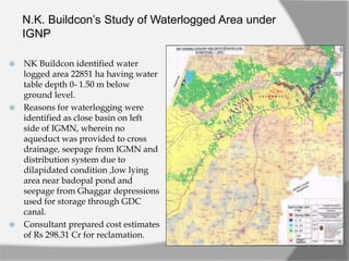
- 1. N.K. Buildcon’s Study of Waterlogged Area under IGNP NK Buildcon identified water logged area 22851 ha having water table depth 0- 1.50 m below ground level. Reasons for waterlogging were identified as close basin on left side of IGMN, wherein no aqueduct was provided to cross drainage, seepage from IGMN and distribution system due to dilapidated condition ,low lying area near badopal pond and seepage from Ghaggar depressions used for storage through GDC canal. Consultant prepared cost estimates of Rs 298.31 Cr for reclamation.
- 2. N.K. Buildcon Study of Waterlogged Area under IGNP Under proposed action plan for reclamation following measures were suggested:- Construction of main drain 157 km long passing under the IGMN and GDC. Construction of Syphons at IGMN at RD 96.3 and Ghaggar Drainage Channel (GDC) at RD 150 Beside that disposal of saline water was given two alternatives; (i) Either pump the water in to Anoopgarh Branch at km 145 of main drain (ii) Carry forward to Ghaggar river bed further downstream. Anoopgarh Shakha
- 3. Need for Revision of N.K. Buildcon Study The proposal of NK Buildcon for reclamation of water logged area costing Rs 298.31 Cr was submitted to CWC MOWR GoI for technical appraisal. During appraisal CGWB MOWR GoI objected to the N.K. Buildcon study reports on the grounds that proposal to drain out the storm water or surplus irrigation water (surface/sub surface) in open drains by gravity flow is not sufficient wherein sections are wide and flow at shallow depth could be another source of waterlogging. NDB took note on this observation and required WRD GoR to revise this study through EMC consultant and further validated by CAD consultant. For this study provision of Rs 1.0 Cr was kept in procurement/investment plan of the project as approved by NDB. As per approved TOR, EMC is entrusted to carry out water logging study based on all kind of data provided by the WRD GoR as and when required by the consultant.
- 4. Preliminary Study by EMC Consultant The consultant identified critically affected area as 10,425 hectare which is either ponded or have water table within 0-3.50 m bgl. This area is proposed to be rehabilitated by surface/sub surface drainage plan. Rest of WL area is anticipated to be rehabilitated with relining of IGF/IGMN & distribution system. This area is divided into three zones Zone I: The proposed area is Gandheri (Rawatsar) to IGMN km 96.30 (Khetwali) on left bank Area -2034 hectares Zone II : The area lies in between right bank of IGMN and left bank of Ghaggar drainage channel (GDC). Area -1027 Hectares Zone III : Major area falls under zone III. The area lies on right bank of GDC covering villages - Bherusari, Jhakhrawali, Zorawarpura, 18 SPD, Labana, Badopal, Manatheri and Jhuriawali Area -7364 hectares. Zone-I Zone-II Zone-III
- 5. Soil Investigations Conducted by EMC Consultant Zone Area Ha Observed Value by Water & Soil Sample test at ICAR, Karnal Type of Soil affected (Saline/Alk aline) Recommendation Value Water Soil EC rang e (ds /m) pH range SAR range me/l Na% range EC range ds /m pH range SAR range me/l Na% range Zone-I 2035 5.9 to 49.1 7.53 to 8.95 24.4 to 56.4 27.7 to 56.5 3.9 to 27.6 7.65 to 8.89 5.4 to 37.0 61.39 to 159.74 Saline EC value<4 ds m^-1 pH < 8.2 esp (Exchangeable Sodium %) <15 SAR <13 Zone-II 1,026 8.7 to 75.9 8.25 to 8.75 24.6 to 84.8 24.7 to 84.8 7.2 to 9.7 8.60 to 9.21 20.7 to 31.2 76.24 to 87.83 Saline EC value<4 ds m^-1 pH < 8.2 esp <15 SAR <13 Zone-III 7.364 3.9 to 11.6 7.5 to 7.7 5.6 to 18.2 52.1 To 68.48 6.0 to 9.3 8.28 to 9.40 11.1 to 17.9 63.42 to 72.98 Saline EC value<4 ds m^-1 pH < 8.2 esp <15 SAR <13 Total area 10,425
- 6. Ground Water Table Observation Study made by EMC
- 7. Reclamation Plan by EMC Consultant For Zone I: Develop/Renovate surface drainage network, to bring the drained water to km. 96.3 of IGMN on left bank and Pump the water in IGMN. Existing pump house to be renovated with VT pump arrangement. For Zone II: Develop network of surface/subsurface drains, bring the saline water near km. 99 of IGMN and pump the drained water in IGMN by constructing a pump house. For Zone III:- Develop network of surface/subsurface drains, bring the saline water up to newly constructed Baropal pump house under separate Sem nivaran head and pump the water up to IGMN at km 165 through series of booster pumps. Zone-I Zone-II Zone-III
- 8. Strategy for Reclamation of Waterlogged Area under IGNP Total water logged area under IGNP-Stage for water table depth upto 0-1.5 m is identified as 22831 ha. Out of this, about 12000 ha area adjoining IGMN and its distribution system is likely to reclaimed with lining and re- sectioning for minimum wetted perimeter of flow for IGMN and distribution system. Rest of critical water logged area (10425 ha) lying in three zones is to be reclaimed by surface and subsurface drainage system. In the first stage 3274 ha will be taken up as pilot project and rest of the area will be taken up after successful implementation of first stage. The planning of system will be made in totality.
- 9. Reclamation Plan for Ist Stage of Waterlogging Reclamation Out of critically waterlogged area proposed for reclamation, WRD GoR has planned to take up 3274 ha in first stage as a pilot project. The details of area proposed in each of zones are:- Zone I- 1151 Hectare Zone II- 1084 Hectare Zone III- 1039 Hectare Total -3274 Hectare
- 10. Work Flow Process and Time Line Adopted for Execution of Waterlogging Reclamation under IGNP Reconnaissance Survey of Target Area & Prepare Concept Note for possible modes of reclamation and required detailed Investigations, issue work orders for survey & investigations WRD GoR to Procure Data for detailed Survey & Investigations EMC to Develop Detailed Plan, & Cost Estimates for WL Reclamation in Target Area in coordination with ICAR Karnal, CAD Consultant and NDB Consultant Detailed Plan & Cost Estimates to be validated by Executive Committee) Issue award for Work Completion of Work for Stage I 14th April 2022 15th Apr 2021 28th Feb 2021 15th Feb 2021 15 Nov 2020 15 Aug 2020 Planning & Design for Second Stage will run in parallel after approval of first stage by Executive Committee & Second Stage is speculated to be completed by 31st March 2023
- 11. Next Milestone before WRD GoR A&F sanction for topographic survey of first stage target area in 3274 ha is under process. Issue of work orders for topographic survey & investigations-15 Aug 20 Completion of topographic survey by end of 15th Nov 20 . Completion of design, drawings, cost estimates and tender documents by EMC – 15th Feb 21 Approval of Executive Committee of RWSRPD by 28th Feb 21. Issue of award for work of First Stage by 15th April 21. Works of stage I are scheduled to be completed by 14th April 22. WRD GoR will initiate survey, design and estimation of second stage just after approval of first stage plan by the executive committee and issue work orders for second stage by 1st Oct 21 and work of second stage will be completed by 31st March 23.
- 12. Waterlogged Area Reclaimed by Relining of IGF/IGMN & Distribution system The level of water table in adjoining water logged area has diminished by 3.0 m. The adjoining waterlogged has now been reclaimed without any secondary treatment. Sources of seepage has been identified and repaired in complete closure. Farmers in these waterlogged area have started sowing wheat which was lying barren for last few decades.
- 13. Flow Chart for Designing a SSD System Information (Climate, Topography, soils, crops, water table & soil salinity) Is SSD System Confirm Outlet Type Choose System Layout Select DC, Drain depth & Spacing Determine Pipe size and grade Is Filter required Finalize Design No No Yes Yes Yes
- 14. • Topographic survey and map of the target area • Data of soil physio-chemical soil properties • Depth and fluctuation of groundwater table • Quality of groundwater • Hydraulic conductivity of the subsoil material • Groundwater level to up which is to maintain on the basis of crops to be grown • Irrigation practices and their requirements Investigations for subsurface drainage System (SSD)
- 15. Layout of tile Sub-Surface Drainage Network System Laterals Main Drains Outlet of Drains Sump well Pump Discharging Point
- 16. Material of tiles Clay, Concrete, PVC/Plastic pipes, Bituminous fiber or steel Pipe material should be: o Resistant to weathering and freezing o Have high density o Have sufficient strength to withstand static and dynamic loads o Have uniformity in shape and wall thickness Synthetic Fiber Pipes PVC Pipes Clay Tile
- 17. Inlet to tile drains: • Allows surface water ingress into the drainage system • These are two types: Blind inlet - cheaper but chances of clogging Surface inlet - have provisions to prevent the trash entering into the drains but costly Outlet for drains: Water from tile drains are discharged into big size surface drains and further carried to disposal location either by gravity or pumping. Gravity outlet - invert level of tile drain is higher than fully supply level of surface drain Pump outlet - invert level of the outlet is higher than FSL in sump. Blind inlet Surface inlet Gravity outlet Pump outlet
- 18. Trenchless plough digging and lying of perforated pipe and designated depth and grade. Manual laying of drain tile and accessory structures Excavation of a trench Laying the tile at predetermined grade, depth and spacing Putting the envelope material and backfilling the soil 6Method of Installation of SSD System
- 19. Prospects of SSD over Surface Drainage Wastage of land is quite less as compared to surface drainage. Less chances of silting/clogging of drains, therefore better design life. It is designed to trap the water ingress in root zone, therefore section size is quite less. It is quite easy to install, with modern implements wherein simultaneous digging and laying of perforated pipes at design depth could be made very easily. The whole process involves land and installation depth data feeding to remote server, where design and actual installation depth and grades could be monitored through data add ins on implements and software application installed on server. Auto cleaning of perforated pipes take place with application of irrigation and ran water overland. Carrier drains depth are quite minimized to cater subsurface water and rain water for C class drainage. Removal of salts from ground water is very effective with fast reclaim. Due to burial nature of system, wastage of top soil is minimum and using optimum grade of filters loss of soil particles could be reduced to zero and only water with dissolved salts is extracted from system. Can be reinstalled after cleaning of pores and replacement of filters.
- 20. Water Logging Reclamation by SSD In Chambal Command A Case Study
- 21. • Chambal Command is irrigated by water released by regeneration of power through series of river valley multipurpose irrigation projects situated on Chamabl River i.e. Gandhisagar, Ranapratapsagar, Gandhisagar dams. • This released water is ultimately diverted into chambal command by Kota Barrage situated in Kota city. • The CCA of chambal command is 385,000 ha of which 229,000 ha lies in Rajasthan. Intro of Chambal Command
- 22. • In Chambal command irrigation was introduced early in the stage of development of project, without implementation of roster warabandi. • Farmers utilized water without any deterrence and exploited with overuse, resulted in increase in water table and accumulation of salt on the surface. • Salinity and waterlogging problems were detected in 1960's. • By 1970's, about 161,000 ha showed evidence of waterlogging (water table within 3 m of the soil surface) and about 25,000 ha was affected by soil salinity. Rise of Soil Salinity & Water Logging in Chambal Command
- 23. • To combat the problem of increase in water table in chambal command RAJAD project was started in 1991, initially for a 7-years period. • It was undertaken jointly by the Governments of India, the State of Rajasthan and Canada. • The main focus of the project was on establishing horizontal gravity based subsurface drainage system in a target area of about 20,000 ha area, preceded by a pilot research project in about 10 percent of the target area to determine various parameters of the design to be followed for the larger area. • The soil survey of about 61,000 ha in CCA was conducted during 1992-95 as a part of this project and 17,500 ha area was found suffering from soil salinity problem. RAJAD Project
- 24. • During 1992-95, experimental test sites were established on 2,100 ha of land to assess the effectiveness of SSD for salinity control and develop the design criteria for the project. • Water table monitoring at 250 ha locations in the drainage blocks indicated that during the crop seasons, nearly 65 percent of the study area had average water table depth within 1 m of the ground surface. About 30 percent of the area had a water table within 2 m. • The soil salinity survey in these drainage blocks, on an 8.5 ha grid showed that about 36 percent of the area was saline (ECe > 4 dS/m and SAR<15) or saline-sodic (ECe > 4 dS/m and SAR>15). • Productivity of crops in salinity affected and non-saline areas of Chambal Command was found as Status of Command before implementation of Pilot Project Crop Crop Yield (quintals/ha) Saline/waterlogged Non-Saline/Non- waterlogged Wheat 17.0 34.0 Mustard 6.1 14.7 Paddy 17.0 29.0 Soybean 10.2 21.8 Berseem 360 520.0 Sugarcane na 567.5
- 25. • Twelve experimental sites, in 1,420 ha, were chosen to best represent the irrigation induced soil salinity and waterlogging conditions in the project area. • SSD was installed in five sites ranging in size from 50-180 ha at spacing of 15, 30, 60 and 75 m and an average depth of 1.2 m. In this area SSD was installed using local excavation equipment. These five sites were intensively monitored to evaluate the effect of drain depth and crop production. • Five larger SSD test sites ranging in size from 118 to 340 ha were installed • These sites were designed with drain spacing of 30, 40 and 60 m and an average depth of 1.2 m. The main purpose of these sites was to demonstrate the applicability of the trenchless plow technology for this region. • Two additional test sites were installed following the development of the design criteria for large scale SSD installation. Implementation of RAJAD Pilot Project
- 26. Impacts of RAJAD Pilot Project Impact Improvement 1. Salinity reclamation (i) Soils with EC 4-8 dS/m (ii) Soils with EC 8-16 dS/m (iii)Soils with EC> 16 dS/m 2-3 years to achieve 3-4 years to achieve >4 years achieve 2 Water table control 20-40 cm draw down in 3-4 days 3 Soil trafficability Advanced by 6-10 days 4 Crop yield 56 percent increase in soybean and 55 percent increase in wheat yields 5 Cropping intensity Increased from 150-160 percent to 170-185 percent
- 27. Cost Economics of RAJAD Pilot Project Assumptions- Capital cost of SSD of Rs. 34,250 per ha, Discount rate of 12 percent Benefits would accrue from the entire SSD installed area, with 30 year life expectancy CALCULATIONS Benefit / Cost ratio : 2.6 Net present value (NPV) per ha : Rs. 54,900 The internal rate of return (IRR) would be 28 percent, which was found to be 2.4 times of the market rate of interest that a farmer pay, if it is fully financed by the farmer.
- 28. Video Clip by AgriDrainage Co.