SlideShare une entreprise Scribd logo
1  sur  41
2. IDEAL - BATCH AND SEMI - BATCH REACTORS
DESIGN
2. 1 The Ideal Batch Reactor
A Batch reactor generally consists of a closed vessel
provided with a means of stirring and where the
temperature is controlled. Figure 2.1 shows such type of
reactor.
Cj
Figure 2.1 Typical batch reactor
In batch reactor,
no material is supplied to or withdrawn from reactor
during the reaction
the reaction proceeds quickly at first, because of high
concentration of all reactants and
the composition is only a function of time.
 due to the well mixing of the composition throughout the
vessel.The total mass of the reaction i.e., concentration
and temperature are identical over the reactor volume
The volume of the batch reactor is the space occupied by the
reacting mixture and it may vary during the course of reaction. In
gas phase, the volume may be varied as required to maintain the
pressure constant.
t1 t2 t
CA,end
CA
CA,0
XA
t
Figure 2.2 Variation of
concentration with time in a
batch reactor
Figure 2.3 Variation of conversion
with time in a batch Reactor
CA,0 t=0
t=t1
t=t2
t=tn
CA,n
Over Reactor Volume
Figure 2.4 The concentration inside the batch reactor
Pressure
Gauge
Movable
Piston
I- Constant Volume II- Variable Volume
Figure 2.5 Batch reactor for gas phase reaction.
The general problem in designing a batch reactor
 is to calculate the volume of the reactor for a certain average
rate of production.
 The volume can be obtained from the required
degree of conversion and the corresponding time.
 The reaction time of a batch reactor can
be determined by using material balance
2.1. 1 Design of batch reactors
It is important to note that we are dealing a process design
not a mechanical design.
For process designing a reactor, we need a
material balance. Noting that in batch reactor, no
material enters or leaves the reaction mixture during the
course of reaction,
The material balance of equation (1.9) for
component A becomes,
 
f
V
dt
A
dn
dV
A
r
0
(2.1)
We know from the condition that the reaction mixture is
perfectly mixed and so no variation in the rate of reaction
throughout the reactor volume takes place. Due to this, we
can take rA out of the integral and we write the equation (2.1)
in the form
dt
A
dn
f
V
A
r  (2.2)
and for the disappearance of reactant A,
 
dt
A
dn
f
V
A
r 

 (2.2.1)
By integration over the period of the reaction to a final mole, we
obtain the basic design equation for a batch reactor.
)
(
0
,
1
A
r
A
dn
A
n
A
n f
V
tr 


 (2.3)
In a batch reactor, we are interested in determining how long
we should keep the reactants in the reactor to achieve a
certain conversion



A
X
A
r
f
V
A
dX
A
n
r
t
0 )
(
0
, (2.4)
Equations (2.3) and (2.4) are the general design equations
showing, the reaction time required for either constant or
variable volume in isothermal or non-isothermal
operation. Thus, the volume of reacting fluid and the
reaction rate remain under the integral sign, since they
both change as reaction proceeds
Time involvement of the operation in batch reactor.
In completing a batch process, four types of periods
are required. These are:
•Preparation time tch, during which a reaction is made
ready and fresh reactants are charged.
•Reaction time, tr, during which the reaction proceeds to
the desired conversion.
•Recovery time, td, during which the product is
discharged and return to the normal operating condition.
•Cleaning time, tcl , during which the reactor is cleaned.
The total time (cycle time), tc, is the time where one
operating cycle of a batch reactor is described.
cl
t
d
t
r
t
ch
t
c
t 


 (2.5)
The capacity of the batch reactor, which is the quantity
of the product obtained per unit time is reduced due to this
auxiliary time, and it is the major limitation of a batch
reactor especially when it is used for a bigger product operation.
To carry out the integration of the design equation (2.4.1),
we need to know how the reaction rate (-rA) varies with the
conversion of the reacting species
Generally given (-rA)as a function of conversion
(concentration), one can find the time of reaction and
eventually also the size of a reactor. We do this by
constructing the so called a Levenspiel plot
1
(-rA)V Equation (2.4)
Area = tr
nA,o
XA,f XA
1
(-rA) Equation (2.4.1)
Area = tr
CA,o
XA,f XA
Figure 2.6 Levenspiel Plots to find the reaction time
The integral also can be evaluated using numerical methods
such as, Trapezoidal rule, Simpson's rule, Five-point
quadratic formula.
As for an illustration, the so called Simpson's one-third rule to
evaluate the integral
         















 f
A
X
A
r
A
X
A
r
A
X
A
r
X
f
A
X
A
r
A
dX
,
1
1
,
4
)
0
,
(
1
3
,
0
Relevant in reactor design
is a mathematical description that can predict reactor outlet
concentration and temperature from
inlet concentration, rate of reaction and reactor
dimensions.
These equations by nature are complicated unless systematically
organized and solved. One way of solving such equations is by
using algorithm.
Algorithm is a rule or calculation procedure for solving a
mathematical problem that frequently involves extensive
numerical operations.
For an example, if we want to design isothermal batch reactor, the
algorithm steps will be as under:
Step1 : We begin by applying our general mole balance
equation to arrive at the design equation of the batch
reactor.
Step2 : We determine the rate equation as the function of
concentrations.
Step3 : We change the concentration in terms of conversion
using stoichiometry relationship.
Step4 : Combine the steps 2 and 3 to obtain    
A
X
f
A
r 

Step5: Evaluate the integral using graphical, numerical,
analytical, software package etc.
Summarizing the algorithm for batch reactor design gives,
Mole Balance and Design Equation.
Rate Law.
Stoichiometry
Combination
Evaluation
2.1.2 Heat Effect on the batch reactors
Generally, all chemical reactions are in principle
accompanied by the evolution(exothermic) or absorption
(endothermic) of heat. Changes of temperature during
reaction are common in reactors This happens deliberately (by
heat exchange with the surroundings) or by the nature of the
reaction. The temperature change due to the nature of reaction
versus conversion is shown in the Figure 2.10
∆HR = 0
T
Conversion, XA
Exothermic
Reaction
Endothermic
Reaction
Exothermic
Figure 2.10 Temperature versus conversion in adiabatic reactors
Endothermic
Exothermic
Isothermal
Initial reaction
Temperature
t
Figure 2.11 Effect of temperature versus time in a batch reactor
In designing a non-isothermal reactor basic design equations i.e.,
rate laws and stochiometry relationship can be used from the
mole balance design equation. The only thing we have
to consider additionally is the change of
temperature during the reaction
Let us consider the following highly exothermic reaction carried
out adiabatically in a batch reactor
B
A
Our object is to calculate the reaction time for 60% conversion.
• Mole balance design equation (2.4.1) gives,



f
A
X
A
r
A
dX
O
A
C
r
t
,
0 )
(
,
• Rate Law, for first order reaction is
  A
kC
A
r 

• Stoichiometry
Liquid phase 0
V
f
V   
A
X
A
C
A
C 
 1
0
,
• Combining and canceling the entering concentration
o
A
C , yields



f
A
X
A
X
k
A
dX
r
t
,
0 )
1
(
Recalling the Arrhenius equation
















T
T
R
E
k
k
1
0
1
exp
0
Since k is a function of temperature and in adiabatic
reaction, temperature is changing during the course of
reaction i.e., k is also varying. This forces us not to take k
outside the integral, hence the overall equation becomes,
 


















f
A
X
A
X
T
o
T
R
E
o
K
A
dX
r
t
.
0 1
1
1
exp
To solve this equation, we need a relation of XA and T.
This type of problems forces us to use both the material and
energy balances. To calculate the heat effect in batch
reactor, we use the energy balance equation as it is
)
(
)
( T
S
T
KA
rV
R
H
dt
dT
P
C
T
m 



(A) Isothermal Batch Reactor
Generally due to the nature of the reaction, the heat is
evolved or absorbed during the reaction, thus it is
hard to imagine a chemical reaction that has a reaction heat
of zero.
Normally to bring in isothermal condition, the reaction is
brought immediately to that of the surrounding by cooling
(if the reaction is exothermic) or heating (if the reaction is
endothermic) i.e., the temperature of the reacting mixture is
maintained constant through out the course of reaction.
This happens with the assistance of the heat transfer
medium under perfectly stirring condition.
In isothermal operation, there is no change of reaction
temperature, i.e., constant temperature (dT = O). If the
reactor is to be operated isothermally, the rate of reaction can
be expressed as a function of concentration only, not as a
function of temperature, then
)
(
)
( T
S
T
KA
rV
R
H 


The material balance can be rearranged
 
dt
A
dX
A
n
R
V
A
r 0
,


Combining the equations gives
   
S
T
T
KA
dt
A
dx
o
A
n
R
H 


 ,
The energy balance equation
Looking to the above equation, the rate of heat
transfer value changes with the rate of reaction.
The rate of reaction is changing with temperature. The
change of temperature is controlled by the heat transfer
equipment, so as to maintain the rate of reaction constant.
The rate of heat transfer
 
T
S
T
KA
Q 

s
T
- can be controlled by changing T
- by changing over-all heat transfer co-efficient K,
which is largely dependant on the agitator speed and
the viscosity of the liquid
Temperature
Controller
Steam
(B) Non – isothermal Batch Reactor
This is sometimes called thermal reactors. Two cases
 During reaction heat absorbed or released,
 there are deliberate acts of heat introduced or removed from
the reactor, which accounts for heat losses to the surrounding.
Thus the design of non-isothermal reactors
requires simultaneous solutions of the material and energy
balance equations
There are a lot of questions to be answered to design
such type of reactors, such as type of materials of
construction, heat transfer equipment etc.
The temperature is not constant and varies during the
course of reaction, then the rate of reaction will be a function of
temperature as well as conversion
The heat balance for non isothemal becomes,
)
(
)
( T
S
T
KA
rV
R
H
dt
dT
P
C
T
m 



Taking as an example of a first-order elementary reaction,
the rate of reaction becomes,    
A
X
A
kC
A
r 

 1
0
,
and the rate constant is defined using Arrhenius Law,







RT
E
A
k .
exp
And rate as a function of both conversion and temperature
becomes
   
A
X
A
C
RT
E
A
A
r 







 1
0
,
exp
Substituting the rate equation to the energy balance for non-
isothermal operation gives,
    
T
S
T
KA
R
V
R
H
A
X
A
C
RT
E
A
dt
dT
P
C
T
m 










 1
0
,
exp
The Equation shows three variables,
time of reaction,
 conversion and
 temperature.
The most important parameter is the reaction time or
eventually the size of a reactor for a particular conversion
The time of a reaction required for a particular conversion
involves simultaneous solutions of the material
 



f
A
X
A
r
A
dx
A
C
r
t
.
0
0
,
and energy balances
Simultaneous solution of material and energy balance in
analytical form is difficult and numerical methods or analogy
simulation must be used. Analytical solution is possible by
using the so called trial and error method
C. Adiabatic Operation
Adiabatic reactors operate without any heat addition
or removal
Based on these facts adiabatic reactors are
inexpensive and are used almost in all the industry.
Adiabatic reactors can be used when:
•The heat of reaction is low where desired conversion and
yield can be attained without excessive temperature change.
•For high exothermic reaction, inerts or excess of one reactant
can be added so that the desired conversion and yield are not
adversely affected by excessive temperature change.
The energy balance for adiabatic batch reactor without heat
transfer equation becomes
)
(rV
R
H
dt
dT
P
C
T
m 


 
dt
A
dX
R
H
A
n
dt
dT
P
C
T
m 

 0
,
  A
dX
R
H
A
n
dT
P
C
T
m 

 0
,
Equation Shows:
•Time is not involved
•Eliminates the need for simultaneous stepwise solution of
the mass and energy balances which was the case for
isothermal reaction
f
T
T 
Differentiation of equation for the initial condition of 0
,
A
X
A
X 
and final condition of
and T = TO f
A
X
A
X ,
 and
     
0
.,
0
,
0 A
X
A
X
A
n
R
H
T
T
P
C
T
m 




with the initial condition, 0
0
, 
A
X the equation can be rearranged
 
P
C
T
m
A
X
A
n
R
H
T
0
,
0
T
-



Let  
P
C
T
m
A
n
R
H
ad
T
0
,




ad
T

is the adiabatic temperature rise of the reaction mixture. This
adiabatic temperature rise indicates about how much the
temperature of the reaction mixture would rise if the reaction
is to proceed adiabatically to completion.
Where
The relationship between the temperature and the
conversion in an adiabatic reactor gives.
A
X
ad
T
T
T 

 0
A
X
ad
T
T
T 

 0
or
 
0
1
T
T
ad
T
A
X 


or
For an assumption of   
,
, R
H
P
C 

are independent of temperature, conversion as a linear function
of temperature is shown in Figure ( 2.13 ). The straight line
described by equation (2.33.2) intersects the temperature axis
at point T = T0 and the slope of such curve becomes.
  0
,
A
n
R
H
P
C
T
m
b



The sign of the slope depends on that of enthalpy change: (-)
exothermic,(+) endothermic
1
Material
balance
Material
balance
1
XA XA
To
T
To
T
Energy
balance
Energy
balance
(a) Endothermic b) Exothermic
Figure 2.13 Variation of conversion versus temperature
The adiabatic temperature rise is one of the most important
characteristics of the mixture.
 It's value depends on the initial composition (initial
condition)
The higher value of adiabatic temperature i.e., the
gradient rise is an indication of a stronger thermal effect
of the reaction mixture.
 These thermal effects can be subdued through the
dilution of the mixture or
 by addition of excessive amounts of some of the
reactants or inerts. This effect is shown in the Figure (2.14)
∆HR > 0 ∆HR < 0
XA
To T
Isothermal
Increase
inerts
Decrease
inerts
Decrease
inerts
Increase
inerts
Figure 2.14 The effects of addition of inerts to the reaction
mixture and the variation of conversion versus temperature in an
adiabatic operation.
2.1.3 Available Technologies A batch reactor is usually
implemented in the industry for small scale operation, mostly
for testing new products that have to be fully developed and for
the processes that are difficult to convert to continuous
operations.
The main advantage of batch reactor are
 high conversion with a long time and
The equipment required to conduct a batch operation is
relatively simple and encompasses.
The disadvantage counts to high labor cost per unit
production and the difficulty in obtaining large scale
production
(A) Reactor
It is often a vertical cylinder with an elliptical bottom. The reactor
should be constructed in such a way that it can withstand vacuum
and some internal pressure. The material used for its
construction is generally suitable for various reactionary
processes. Most often used is a glass-lined steel vessel.
This type of reactor is used especially for high corrosion
materials. Table 2.2 gives the main characteristics of a standard
reactors that are sold commercially. Figure 2.15 shows the
illustrations of a simple batch reactor working in the industry.
Table 2.2 Main characteristics of standard reactors available in the
market
Capacity
(m3)
8 14 25 32 10 20 25 1 4 10 25 0.7
Diameter
(m)
2 2.50 2.80 3.10 2.40 2.80 3.00 1.20 1.80 2.40 3.00 0.9
Total weight
(kg)
945
0
13,90
0
21,30
0
24,10
0
11000 1800
0
2180
0
1830 2500 5200 7900 800
Exchange
area(m2) (1)
18.6 26.6 40.0 45.6 19.8 33 38.8 4.45 10.9
0
11.15 19.5
0
3.4
DE DE DE DE DE DE DE DE DE SE SE DE
Service
Pressure(bar
)
1.5 1.5 1.5 1.5 6 6 6 6 6 6 6 1.5
Material)
AV AV AV AV AV AV AV AI AI AI AI V
DE = double jacket, SE = welded external coil, AV = glass-lined steel, AI = Stainless steel, V=
(B) Heat Exchanger
The heat exchanger can be located inside the reactor (coil,
plates) outside it (conventional heat exchanger) or could be
manufactured together with the reactor wall (double jacket).
Figure 2.16 -2.18 illustrates different type of a reactor with heat
exchange mechanism
Figure 2. 16 Batch reactor with double jacket
Figure 2.17 Batch reactor with external heat exchange
Figure 2.18 Batch reactor with double jacket and internal coil
(C) Stirrer
Stirrer is used to mix the reactor contents uniformly so that
the concentration remains the same throughout the reactor.
There are a number of stirrers used in the technology, such as
marine -, turbine-, vane disc-, paddle-, anchor-, double motion-,
etc. stirrers. The selection of stirrer type, its dimensions and
arrangement are dependant on the type of fluid in the reactor and
the stirring is achieved in the operation.
(D) Auxiliaries
Water, steam, or a heat transfer medium, electrical energy etc.
can be used in the operation
2.2 Ideal semi-batch reactor design
The semi-batch reactor is a tank type operated on a non-
steady flow basis. Semi-batch occurs when some reactants are
charged into the reactor at time zero, while other reactants are
added during the reaction. Figure 2.17 illustrate typical semi-batch
reactor.
CA,0
Cj
Figure 2.19 Semi-batch reactor
Semi-batch reactor is inevitable when:
•It is essential to regulate the heat effect of high exothermic
reaction. This can be achieved through regulating the rate of
addition of one of the reactants so that the energy evolution
can be controlled.
•To minimize unwanted side products by maintaining low
concentration of one of the reactants, where it is possible to
maximize the selectivity of the product especially in the liquid
phase reaction.
•It is required to remove one of the products to increase the
equilibrium of the reaction to the application of Le Chatelier’s
principle
1.Material balance
For the semi-batch reactor design all the four terms in the
general mass balance of equation (1.9) may have to be
considered.
-
V
dV
j
r
j
F
-
j,0
F 


dt
j
dn
The mass balance for the reactant A after rearranging becomes
 
V
A
r
A
F
-
A,0
F

dt
A
VC
d
This equation can be integrated with numerical procedure.
Analytical integral is possible for the case of constants of the
feed and exit rates of the feed composition; density and
additional criteria is that it must be a first-order.
 
dt
A
VC
d
V
A
r
-
A
C
f
V,
F
-
A,0
C
V,0
F 
For constant densities along constant flow rate
 
dt
A
C
d
V
V
A
r
-
A
C
V,0
F
-
A,0
C
V,0
F 
or  
dt
A
C
d
V,0
F
V
V,0
F
V
A
r
-
A
C
-
A,0
C 
Using the definition of space time, we have
V,0
F
V

F

 
dt
A
C
d
F
F
A
r
-
A
C
-
A,0
C 
 
For a first-order reaction, the rate law is A
kC
)
( 
 A
r
We can combine the rate law and the above equation becomes
dt
A
dC
F
F
A
kC
-
A
C
-
A,0
C 
 
Dividing by and rearranging gives,
F

F
A
C
F
dt
A
dC


0
,
k
1
A
C 








This is the linear differential equation, which can be
integrated analytically. By doing so, we obtain variation of
concentration with time for a first-order reaction in semi-batch
operation
k
1
-
e
I
k
1
0
,
A
C















 F
F
F
A
C 


For addition of a substance to a reactor causes to vary the
volume of the reactor with time. The reactor volume at any time
can be found, using mass balance equation (1.9). The equation
(1.9) can be further simplified for this condition as,
 
A,0
F
dt
V
A
C
d

Utilizing the definition of FA,O , we have
 
A,0
C
V,0
F
dt
V
A
C
d

or  
V,0
F
0 dt
V
d 
 
For a constant density system, 
0  we have V,0
F
dt
dV

With initial condition V=VO at t=0, by integration gives volume as
function of time for semi-batch operation,
t
V,0
F
0
V
V 

2. Energy Balance
The energy balance for semi- batch operation can be written
using all items in energy balance of equation( 1.10.3), namely
)
(
)
(
)
( T
S
T
KA
E
H
F
H
rV
R
H
dt
dT
P
C
T
m 





The equation shows the variation involving both composition
and temperature as a function of time. Solving such equation
is problematic unless we have reduced the variables.
)
(
)
0
(
)
( T
S
T
KA
R
T
T
P
C
T
F
rV
R
H
dt
dT
P
C
T
m 






or

Contenu connexe

Tendances (20)

Chemical reaction engineering
Chemical reaction engineeringChemical reaction engineering
Chemical reaction engineering
 
Reactor types.ppt
Reactor types.pptReactor types.ppt
Reactor types.ppt
 
Ideal reactor
Ideal reactorIdeal reactor
Ideal reactor
 
Catalytic reactors
Catalytic reactorsCatalytic reactors
Catalytic reactors
 
Tubular reactor
Tubular reactorTubular reactor
Tubular reactor
 
Fixed bed
Fixed bedFixed bed
Fixed bed
 
Cre ppt
Cre pptCre ppt
Cre ppt
 
Series parallel reaction (no-24)
Series parallel reaction (no-24)Series parallel reaction (no-24)
Series parallel reaction (no-24)
 
Convective mass transfer
Convective mass transferConvective mass transfer
Convective mass transfer
 
Plug Flow Reactor
Plug Flow ReactorPlug Flow Reactor
Plug Flow Reactor
 
Material balance
Material balanceMaterial balance
Material balance
 
Material and energy balances
Material and energy balancesMaterial and energy balances
Material and energy balances
 
Mass transfer
Mass transferMass transfer
Mass transfer
 
1.1 Vapor Liquid Equilibrium
1.1 Vapor Liquid Equilibrium1.1 Vapor Liquid Equilibrium
1.1 Vapor Liquid Equilibrium
 
Advanced Chemical Reaction Engineering-Part-1-10-Apr-2016
Advanced Chemical Reaction Engineering-Part-1-10-Apr-2016Advanced Chemical Reaction Engineering-Part-1-10-Apr-2016
Advanced Chemical Reaction Engineering-Part-1-10-Apr-2016
 
Differential method of analysis of data
Differential method of analysis of dataDifferential method of analysis of data
Differential method of analysis of data
 
FAQ on chemical Reaction Engineering
FAQ on chemical Reaction EngineeringFAQ on chemical Reaction Engineering
FAQ on chemical Reaction Engineering
 
Presentation reactors
Presentation reactorsPresentation reactors
Presentation reactors
 
Types of reactor
Types of reactorTypes of reactor
Types of reactor
 
chemical reaction engineering
chemical reaction engineeringchemical reaction engineering
chemical reaction engineering
 

Similaire à Rea 2.ppt

Reaktor Alir Tangki Berpengaduk
Reaktor Alir Tangki BerpengadukReaktor Alir Tangki Berpengaduk
Reaktor Alir Tangki BerpengadukLeo Simanjuntak
 
Mathematical modeling of continuous stirred tank reactor systems (cstr)
Mathematical modeling of continuous stirred tank reactor systems (cstr)Mathematical modeling of continuous stirred tank reactor systems (cstr)
Mathematical modeling of continuous stirred tank reactor systems (cstr)Karnav Rana
 
Chemical Kinetics in Unit Processes
Chemical Kinetics in Unit ProcessesChemical Kinetics in Unit Processes
Chemical Kinetics in Unit ProcessesRahul Gaur
 
Lecture 9_Packed Bed Reactor Design_FIR.pdf
Lecture 9_Packed Bed Reactor Design_FIR.pdfLecture 9_Packed Bed Reactor Design_FIR.pdf
Lecture 9_Packed Bed Reactor Design_FIR.pdfDr. Rashmi Walvekar
 
Simultaneousnonlinear two dimensional modeling of tubular reactor of hydrogen...
Simultaneousnonlinear two dimensional modeling of tubular reactor of hydrogen...Simultaneousnonlinear two dimensional modeling of tubular reactor of hydrogen...
Simultaneousnonlinear two dimensional modeling of tubular reactor of hydrogen...Arash Nasiri
 
247447699 reactors
247447699 reactors247447699 reactors
247447699 reactorsmanojg1990
 
Reaction Kinetics.really detailed and educational
Reaction Kinetics.really detailed and educationalReaction Kinetics.really detailed and educational
Reaction Kinetics.really detailed and educationalHayaaKhan8
 
kinetics of stability Molecular pharmaceutics
kinetics of stability Molecular pharmaceuticskinetics of stability Molecular pharmaceutics
kinetics of stability Molecular pharmaceuticsMittalGandhi
 
Chemical Reaction Engineering Lab v3.0
Chemical Reaction Engineering Lab v3.0Chemical Reaction Engineering Lab v3.0
Chemical Reaction Engineering Lab v3.0Michael Garibaldi
 
12 chemistry impq_ch04_chemical_kinetics_02
12 chemistry impq_ch04_chemical_kinetics_0212 chemistry impq_ch04_chemical_kinetics_02
12 chemistry impq_ch04_chemical_kinetics_02B Bhuvanesh
 
Design of a self tuning regulator for temperature control of a polymerization...
Design of a self tuning regulator for temperature control of a polymerization...Design of a self tuning regulator for temperature control of a polymerization...
Design of a self tuning regulator for temperature control of a polymerization...ISA Interchange
 
class 12 chemicalkinetics.pptx
class 12 chemicalkinetics.pptxclass 12 chemicalkinetics.pptx
class 12 chemicalkinetics.pptxarjitkatiyar0
 
AP Chemistry Chapter 14 Outline
AP Chemistry Chapter 14 OutlineAP Chemistry Chapter 14 Outline
AP Chemistry Chapter 14 OutlineJane Hamze
 

Similaire à Rea 2.ppt (20)

Reaktor Alir Tangki Berpengaduk
Reaktor Alir Tangki BerpengadukReaktor Alir Tangki Berpengaduk
Reaktor Alir Tangki Berpengaduk
 
GroupW _Kinetics
GroupW _KineticsGroupW _Kinetics
GroupW _Kinetics
 
experiment Cstr 40l
experiment Cstr 40lexperiment Cstr 40l
experiment Cstr 40l
 
Mathematical modeling of continuous stirred tank reactor systems (cstr)
Mathematical modeling of continuous stirred tank reactor systems (cstr)Mathematical modeling of continuous stirred tank reactor systems (cstr)
Mathematical modeling of continuous stirred tank reactor systems (cstr)
 
Chemical Kinetics in Unit Processes
Chemical Kinetics in Unit ProcessesChemical Kinetics in Unit Processes
Chemical Kinetics in Unit Processes
 
Lecture 9_Packed Bed Reactor Design_FIR.pdf
Lecture 9_Packed Bed Reactor Design_FIR.pdfLecture 9_Packed Bed Reactor Design_FIR.pdf
Lecture 9_Packed Bed Reactor Design_FIR.pdf
 
Simultaneousnonlinear two dimensional modeling of tubular reactor of hydrogen...
Simultaneousnonlinear two dimensional modeling of tubular reactor of hydrogen...Simultaneousnonlinear two dimensional modeling of tubular reactor of hydrogen...
Simultaneousnonlinear two dimensional modeling of tubular reactor of hydrogen...
 
Simultaneousnonlinear two dimensional modeling of tubular reactor of hydrogen...
Simultaneousnonlinear two dimensional modeling of tubular reactor of hydrogen...Simultaneousnonlinear two dimensional modeling of tubular reactor of hydrogen...
Simultaneousnonlinear two dimensional modeling of tubular reactor of hydrogen...
 
Reactors
ReactorsReactors
Reactors
 
247447699 reactors
247447699 reactors247447699 reactors
247447699 reactors
 
Reaction Kinetics.really detailed and educational
Reaction Kinetics.really detailed and educationalReaction Kinetics.really detailed and educational
Reaction Kinetics.really detailed and educational
 
kinetics of stability Molecular pharmaceutics
kinetics of stability Molecular pharmaceuticskinetics of stability Molecular pharmaceutics
kinetics of stability Molecular pharmaceutics
 
Leo...
Leo...Leo...
Leo...
 
Chemical Reaction Engineering Lab v3.0
Chemical Reaction Engineering Lab v3.0Chemical Reaction Engineering Lab v3.0
Chemical Reaction Engineering Lab v3.0
 
Reactor Design 1
Reactor Design 1Reactor Design 1
Reactor Design 1
 
12 chemistry impq_ch04_chemical_kinetics_02
12 chemistry impq_ch04_chemical_kinetics_0212 chemistry impq_ch04_chemical_kinetics_02
12 chemistry impq_ch04_chemical_kinetics_02
 
Design of a self tuning regulator for temperature control of a polymerization...
Design of a self tuning regulator for temperature control of a polymerization...Design of a self tuning regulator for temperature control of a polymerization...
Design of a self tuning regulator for temperature control of a polymerization...
 
class 12 chemicalkinetics.pptx
class 12 chemicalkinetics.pptxclass 12 chemicalkinetics.pptx
class 12 chemicalkinetics.pptx
 
Kinetics pp
Kinetics ppKinetics pp
Kinetics pp
 
AP Chemistry Chapter 14 Outline
AP Chemistry Chapter 14 OutlineAP Chemistry Chapter 14 Outline
AP Chemistry Chapter 14 Outline
 

Dernier

Unleashing the Power of the SORA AI lastest leap
Unleashing the Power of the SORA AI lastest leapUnleashing the Power of the SORA AI lastest leap
Unleashing the Power of the SORA AI lastest leapRishantSharmaFr
 
Computer Networks Basics of Network Devices
Computer Networks  Basics of Network DevicesComputer Networks  Basics of Network Devices
Computer Networks Basics of Network DevicesChandrakantDivate1
 
A Study of Urban Area Plan for Pabna Municipality
A Study of Urban Area Plan for Pabna MunicipalityA Study of Urban Area Plan for Pabna Municipality
A Study of Urban Area Plan for Pabna MunicipalityMorshed Ahmed Rahath
 
Bhubaneswar🌹Call Girls Bhubaneswar ❤Komal 9777949614 💟 Full Trusted CALL GIRL...
Bhubaneswar🌹Call Girls Bhubaneswar ❤Komal 9777949614 💟 Full Trusted CALL GIRL...Bhubaneswar🌹Call Girls Bhubaneswar ❤Komal 9777949614 💟 Full Trusted CALL GIRL...
Bhubaneswar🌹Call Girls Bhubaneswar ❤Komal 9777949614 💟 Full Trusted CALL GIRL...Call Girls Mumbai
 
HOA1&2 - Module 3 - PREHISTORCI ARCHITECTURE OF KERALA.pptx
HOA1&2 - Module 3 - PREHISTORCI ARCHITECTURE OF KERALA.pptxHOA1&2 - Module 3 - PREHISTORCI ARCHITECTURE OF KERALA.pptx
HOA1&2 - Module 3 - PREHISTORCI ARCHITECTURE OF KERALA.pptxSCMS School of Architecture
 
Block diagram reduction techniques in control systems.ppt
Block diagram reduction techniques in control systems.pptBlock diagram reduction techniques in control systems.ppt
Block diagram reduction techniques in control systems.pptNANDHAKUMARA10
 
"Lesotho Leaps Forward: A Chronicle of Transformative Developments"
"Lesotho Leaps Forward: A Chronicle of Transformative Developments""Lesotho Leaps Forward: A Chronicle of Transformative Developments"
"Lesotho Leaps Forward: A Chronicle of Transformative Developments"mphochane1998
 
NO1 Top No1 Amil Baba In Azad Kashmir, Kashmir Black Magic Specialist Expert ...
NO1 Top No1 Amil Baba In Azad Kashmir, Kashmir Black Magic Specialist Expert ...NO1 Top No1 Amil Baba In Azad Kashmir, Kashmir Black Magic Specialist Expert ...
NO1 Top No1 Amil Baba In Azad Kashmir, Kashmir Black Magic Specialist Expert ...Amil baba
 
Unit 4_Part 1 CSE2001 Exception Handling and Function Template and Class Temp...
Unit 4_Part 1 CSE2001 Exception Handling and Function Template and Class Temp...Unit 4_Part 1 CSE2001 Exception Handling and Function Template and Class Temp...
Unit 4_Part 1 CSE2001 Exception Handling and Function Template and Class Temp...drmkjayanthikannan
 
Thermal Engineering Unit - I & II . ppt
Thermal Engineering  Unit - I & II . pptThermal Engineering  Unit - I & II . ppt
Thermal Engineering Unit - I & II . pptDineshKumar4165
 
Online food ordering system project report.pdf
Online food ordering system project report.pdfOnline food ordering system project report.pdf
Online food ordering system project report.pdfKamal Acharya
 
DC MACHINE-Motoring and generation, Armature circuit equation
DC MACHINE-Motoring and generation, Armature circuit equationDC MACHINE-Motoring and generation, Armature circuit equation
DC MACHINE-Motoring and generation, Armature circuit equationBhangaleSonal
 
Thermal Engineering-R & A / C - unit - V
Thermal Engineering-R & A / C - unit - VThermal Engineering-R & A / C - unit - V
Thermal Engineering-R & A / C - unit - VDineshKumar4165
 
XXXXXXXXXXXXXXXXXXXXXXXXXXXXXXXXXXXXXXXXXXXXXXXXXXXX
XXXXXXXXXXXXXXXXXXXXXXXXXXXXXXXXXXXXXXXXXXXXXXXXXXXXXXXXXXXXXXXXXXXXXXXXXXXXXXXXXXXXXXXXXXXXXXXXXXXXXXXX
XXXXXXXXXXXXXXXXXXXXXXXXXXXXXXXXXXXXXXXXXXXXXXXXXXXXssuser89054b
 
Double Revolving field theory-how the rotor develops torque
Double Revolving field theory-how the rotor develops torqueDouble Revolving field theory-how the rotor develops torque
Double Revolving field theory-how the rotor develops torqueBhangaleSonal
 
Online electricity billing project report..pdf
Online electricity billing project report..pdfOnline electricity billing project report..pdf
Online electricity billing project report..pdfKamal Acharya
 
Tamil Call Girls Bhayandar WhatsApp +91-9930687706, Best Service
Tamil Call Girls Bhayandar WhatsApp +91-9930687706, Best ServiceTamil Call Girls Bhayandar WhatsApp +91-9930687706, Best Service
Tamil Call Girls Bhayandar WhatsApp +91-9930687706, Best Servicemeghakumariji156
 
GEAR TRAIN- BASIC CONCEPTS AND WORKING PRINCIPLE
GEAR TRAIN- BASIC CONCEPTS AND WORKING PRINCIPLEGEAR TRAIN- BASIC CONCEPTS AND WORKING PRINCIPLE
GEAR TRAIN- BASIC CONCEPTS AND WORKING PRINCIPLEselvakumar948
 

Dernier (20)

Unleashing the Power of the SORA AI lastest leap
Unleashing the Power of the SORA AI lastest leapUnleashing the Power of the SORA AI lastest leap
Unleashing the Power of the SORA AI lastest leap
 
Computer Networks Basics of Network Devices
Computer Networks  Basics of Network DevicesComputer Networks  Basics of Network Devices
Computer Networks Basics of Network Devices
 
A Study of Urban Area Plan for Pabna Municipality
A Study of Urban Area Plan for Pabna MunicipalityA Study of Urban Area Plan for Pabna Municipality
A Study of Urban Area Plan for Pabna Municipality
 
Bhubaneswar🌹Call Girls Bhubaneswar ❤Komal 9777949614 💟 Full Trusted CALL GIRL...
Bhubaneswar🌹Call Girls Bhubaneswar ❤Komal 9777949614 💟 Full Trusted CALL GIRL...Bhubaneswar🌹Call Girls Bhubaneswar ❤Komal 9777949614 💟 Full Trusted CALL GIRL...
Bhubaneswar🌹Call Girls Bhubaneswar ❤Komal 9777949614 💟 Full Trusted CALL GIRL...
 
HOA1&2 - Module 3 - PREHISTORCI ARCHITECTURE OF KERALA.pptx
HOA1&2 - Module 3 - PREHISTORCI ARCHITECTURE OF KERALA.pptxHOA1&2 - Module 3 - PREHISTORCI ARCHITECTURE OF KERALA.pptx
HOA1&2 - Module 3 - PREHISTORCI ARCHITECTURE OF KERALA.pptx
 
Block diagram reduction techniques in control systems.ppt
Block diagram reduction techniques in control systems.pptBlock diagram reduction techniques in control systems.ppt
Block diagram reduction techniques in control systems.ppt
 
Integrated Test Rig For HTFE-25 - Neometrix
Integrated Test Rig For HTFE-25 - NeometrixIntegrated Test Rig For HTFE-25 - Neometrix
Integrated Test Rig For HTFE-25 - Neometrix
 
"Lesotho Leaps Forward: A Chronicle of Transformative Developments"
"Lesotho Leaps Forward: A Chronicle of Transformative Developments""Lesotho Leaps Forward: A Chronicle of Transformative Developments"
"Lesotho Leaps Forward: A Chronicle of Transformative Developments"
 
NO1 Top No1 Amil Baba In Azad Kashmir, Kashmir Black Magic Specialist Expert ...
NO1 Top No1 Amil Baba In Azad Kashmir, Kashmir Black Magic Specialist Expert ...NO1 Top No1 Amil Baba In Azad Kashmir, Kashmir Black Magic Specialist Expert ...
NO1 Top No1 Amil Baba In Azad Kashmir, Kashmir Black Magic Specialist Expert ...
 
Unit 4_Part 1 CSE2001 Exception Handling and Function Template and Class Temp...
Unit 4_Part 1 CSE2001 Exception Handling and Function Template and Class Temp...Unit 4_Part 1 CSE2001 Exception Handling and Function Template and Class Temp...
Unit 4_Part 1 CSE2001 Exception Handling and Function Template and Class Temp...
 
Thermal Engineering Unit - I & II . ppt
Thermal Engineering  Unit - I & II . pptThermal Engineering  Unit - I & II . ppt
Thermal Engineering Unit - I & II . ppt
 
Cara Menggugurkan Sperma Yang Masuk Rahim Biyar Tidak Hamil
Cara Menggugurkan Sperma Yang Masuk Rahim Biyar Tidak HamilCara Menggugurkan Sperma Yang Masuk Rahim Biyar Tidak Hamil
Cara Menggugurkan Sperma Yang Masuk Rahim Biyar Tidak Hamil
 
Online food ordering system project report.pdf
Online food ordering system project report.pdfOnline food ordering system project report.pdf
Online food ordering system project report.pdf
 
DC MACHINE-Motoring and generation, Armature circuit equation
DC MACHINE-Motoring and generation, Armature circuit equationDC MACHINE-Motoring and generation, Armature circuit equation
DC MACHINE-Motoring and generation, Armature circuit equation
 
Thermal Engineering-R & A / C - unit - V
Thermal Engineering-R & A / C - unit - VThermal Engineering-R & A / C - unit - V
Thermal Engineering-R & A / C - unit - V
 
XXXXXXXXXXXXXXXXXXXXXXXXXXXXXXXXXXXXXXXXXXXXXXXXXXXX
XXXXXXXXXXXXXXXXXXXXXXXXXXXXXXXXXXXXXXXXXXXXXXXXXXXXXXXXXXXXXXXXXXXXXXXXXXXXXXXXXXXXXXXXXXXXXXXXXXXXXXXX
XXXXXXXXXXXXXXXXXXXXXXXXXXXXXXXXXXXXXXXXXXXXXXXXXXXX
 
Double Revolving field theory-how the rotor develops torque
Double Revolving field theory-how the rotor develops torqueDouble Revolving field theory-how the rotor develops torque
Double Revolving field theory-how the rotor develops torque
 
Online electricity billing project report..pdf
Online electricity billing project report..pdfOnline electricity billing project report..pdf
Online electricity billing project report..pdf
 
Tamil Call Girls Bhayandar WhatsApp +91-9930687706, Best Service
Tamil Call Girls Bhayandar WhatsApp +91-9930687706, Best ServiceTamil Call Girls Bhayandar WhatsApp +91-9930687706, Best Service
Tamil Call Girls Bhayandar WhatsApp +91-9930687706, Best Service
 
GEAR TRAIN- BASIC CONCEPTS AND WORKING PRINCIPLE
GEAR TRAIN- BASIC CONCEPTS AND WORKING PRINCIPLEGEAR TRAIN- BASIC CONCEPTS AND WORKING PRINCIPLE
GEAR TRAIN- BASIC CONCEPTS AND WORKING PRINCIPLE
 

Rea 2.ppt

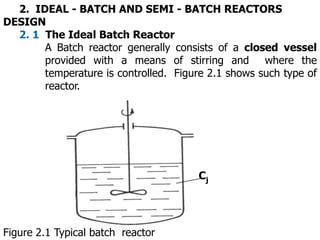
  • 1. 2. IDEAL - BATCH AND SEMI - BATCH REACTORS DESIGN 2. 1 The Ideal Batch Reactor A Batch reactor generally consists of a closed vessel provided with a means of stirring and where the temperature is controlled. Figure 2.1 shows such type of reactor. Cj Figure 2.1 Typical batch reactor
  • 2. In batch reactor, no material is supplied to or withdrawn from reactor during the reaction the reaction proceeds quickly at first, because of high concentration of all reactants and the composition is only a function of time.  due to the well mixing of the composition throughout the vessel.The total mass of the reaction i.e., concentration and temperature are identical over the reactor volume The volume of the batch reactor is the space occupied by the reacting mixture and it may vary during the course of reaction. In gas phase, the volume may be varied as required to maintain the pressure constant.
  • 3. t1 t2 t CA,end CA CA,0 XA t Figure 2.2 Variation of concentration with time in a batch reactor Figure 2.3 Variation of conversion with time in a batch Reactor
  • 4. CA,0 t=0 t=t1 t=t2 t=tn CA,n Over Reactor Volume Figure 2.4 The concentration inside the batch reactor
  • 5. Pressure Gauge Movable Piston I- Constant Volume II- Variable Volume Figure 2.5 Batch reactor for gas phase reaction. The general problem in designing a batch reactor  is to calculate the volume of the reactor for a certain average rate of production.  The volume can be obtained from the required degree of conversion and the corresponding time.  The reaction time of a batch reactor can be determined by using material balance
  • 6. 2.1. 1 Design of batch reactors It is important to note that we are dealing a process design not a mechanical design. For process designing a reactor, we need a material balance. Noting that in batch reactor, no material enters or leaves the reaction mixture during the course of reaction, The material balance of equation (1.9) for component A becomes,   f V dt A dn dV A r 0 (2.1) We know from the condition that the reaction mixture is perfectly mixed and so no variation in the rate of reaction throughout the reactor volume takes place. Due to this, we can take rA out of the integral and we write the equation (2.1) in the form
  • 7. dt A dn f V A r  (2.2) and for the disappearance of reactant A,   dt A dn f V A r    (2.2.1) By integration over the period of the reaction to a final mole, we obtain the basic design equation for a batch reactor. ) ( 0 , 1 A r A dn A n A n f V tr     (2.3) In a batch reactor, we are interested in determining how long we should keep the reactants in the reactor to achieve a certain conversion    A X A r f V A dX A n r t 0 ) ( 0 , (2.4)
  • 8. Equations (2.3) and (2.4) are the general design equations showing, the reaction time required for either constant or variable volume in isothermal or non-isothermal operation. Thus, the volume of reacting fluid and the reaction rate remain under the integral sign, since they both change as reaction proceeds Time involvement of the operation in batch reactor. In completing a batch process, four types of periods are required. These are: •Preparation time tch, during which a reaction is made ready and fresh reactants are charged. •Reaction time, tr, during which the reaction proceeds to the desired conversion. •Recovery time, td, during which the product is discharged and return to the normal operating condition. •Cleaning time, tcl , during which the reactor is cleaned.
  • 9. The total time (cycle time), tc, is the time where one operating cycle of a batch reactor is described. cl t d t r t ch t c t     (2.5) The capacity of the batch reactor, which is the quantity of the product obtained per unit time is reduced due to this auxiliary time, and it is the major limitation of a batch reactor especially when it is used for a bigger product operation. To carry out the integration of the design equation (2.4.1), we need to know how the reaction rate (-rA) varies with the conversion of the reacting species Generally given (-rA)as a function of conversion (concentration), one can find the time of reaction and eventually also the size of a reactor. We do this by constructing the so called a Levenspiel plot
  • 10. 1 (-rA)V Equation (2.4) Area = tr nA,o XA,f XA 1 (-rA) Equation (2.4.1) Area = tr CA,o XA,f XA Figure 2.6 Levenspiel Plots to find the reaction time The integral also can be evaluated using numerical methods such as, Trapezoidal rule, Simpson's rule, Five-point quadratic formula. As for an illustration, the so called Simpson's one-third rule to evaluate the integral                           f A X A r A X A r A X A r X f A X A r A dX , 1 1 , 4 ) 0 , ( 1 3 , 0
  • 11. Relevant in reactor design is a mathematical description that can predict reactor outlet concentration and temperature from inlet concentration, rate of reaction and reactor dimensions. These equations by nature are complicated unless systematically organized and solved. One way of solving such equations is by using algorithm. Algorithm is a rule or calculation procedure for solving a mathematical problem that frequently involves extensive numerical operations. For an example, if we want to design isothermal batch reactor, the algorithm steps will be as under:
  • 12. Step1 : We begin by applying our general mole balance equation to arrive at the design equation of the batch reactor. Step2 : We determine the rate equation as the function of concentrations. Step3 : We change the concentration in terms of conversion using stoichiometry relationship. Step4 : Combine the steps 2 and 3 to obtain     A X f A r   Step5: Evaluate the integral using graphical, numerical, analytical, software package etc. Summarizing the algorithm for batch reactor design gives, Mole Balance and Design Equation. Rate Law. Stoichiometry Combination Evaluation
  • 13. 2.1.2 Heat Effect on the batch reactors Generally, all chemical reactions are in principle accompanied by the evolution(exothermic) or absorption (endothermic) of heat. Changes of temperature during reaction are common in reactors This happens deliberately (by heat exchange with the surroundings) or by the nature of the reaction. The temperature change due to the nature of reaction versus conversion is shown in the Figure 2.10 ∆HR = 0 T Conversion, XA Exothermic Reaction Endothermic Reaction Exothermic Figure 2.10 Temperature versus conversion in adiabatic reactors
  • 14. Endothermic Exothermic Isothermal Initial reaction Temperature t Figure 2.11 Effect of temperature versus time in a batch reactor In designing a non-isothermal reactor basic design equations i.e., rate laws and stochiometry relationship can be used from the mole balance design equation. The only thing we have to consider additionally is the change of temperature during the reaction
  • 15. Let us consider the following highly exothermic reaction carried out adiabatically in a batch reactor B A Our object is to calculate the reaction time for 60% conversion. • Mole balance design equation (2.4.1) gives,    f A X A r A dX O A C r t , 0 ) ( , • Rate Law, for first order reaction is   A kC A r   • Stoichiometry Liquid phase 0 V f V    A X A C A C   1 0 , • Combining and canceling the entering concentration o A C , yields    f A X A X k A dX r t , 0 ) 1 ( Recalling the Arrhenius equation                 T T R E k k 1 0 1 exp 0
  • 16. Since k is a function of temperature and in adiabatic reaction, temperature is changing during the course of reaction i.e., k is also varying. This forces us not to take k outside the integral, hence the overall equation becomes,                     f A X A X T o T R E o K A dX r t . 0 1 1 1 exp To solve this equation, we need a relation of XA and T. This type of problems forces us to use both the material and energy balances. To calculate the heat effect in batch reactor, we use the energy balance equation as it is ) ( ) ( T S T KA rV R H dt dT P C T m    
  • 17. (A) Isothermal Batch Reactor Generally due to the nature of the reaction, the heat is evolved or absorbed during the reaction, thus it is hard to imagine a chemical reaction that has a reaction heat of zero. Normally to bring in isothermal condition, the reaction is brought immediately to that of the surrounding by cooling (if the reaction is exothermic) or heating (if the reaction is endothermic) i.e., the temperature of the reacting mixture is maintained constant through out the course of reaction. This happens with the assistance of the heat transfer medium under perfectly stirring condition. In isothermal operation, there is no change of reaction temperature, i.e., constant temperature (dT = O). If the reactor is to be operated isothermally, the rate of reaction can be expressed as a function of concentration only, not as a function of temperature, then
  • 18. ) ( ) ( T S T KA rV R H    The material balance can be rearranged   dt A dX A n R V A r 0 ,   Combining the equations gives     S T T KA dt A dx o A n R H     , The energy balance equation Looking to the above equation, the rate of heat transfer value changes with the rate of reaction. The rate of reaction is changing with temperature. The change of temperature is controlled by the heat transfer equipment, so as to maintain the rate of reaction constant.
  • 19. The rate of heat transfer   T S T KA Q   s T - can be controlled by changing T - by changing over-all heat transfer co-efficient K, which is largely dependant on the agitator speed and the viscosity of the liquid Temperature Controller Steam
  • 20. (B) Non – isothermal Batch Reactor This is sometimes called thermal reactors. Two cases  During reaction heat absorbed or released,  there are deliberate acts of heat introduced or removed from the reactor, which accounts for heat losses to the surrounding. Thus the design of non-isothermal reactors requires simultaneous solutions of the material and energy balance equations There are a lot of questions to be answered to design such type of reactors, such as type of materials of construction, heat transfer equipment etc. The temperature is not constant and varies during the course of reaction, then the rate of reaction will be a function of temperature as well as conversion
  • 21. The heat balance for non isothemal becomes, ) ( ) ( T S T KA rV R H dt dT P C T m     Taking as an example of a first-order elementary reaction, the rate of reaction becomes,     A X A kC A r    1 0 , and the rate constant is defined using Arrhenius Law,        RT E A k . exp And rate as a function of both conversion and temperature becomes     A X A C RT E A A r          1 0 , exp Substituting the rate equation to the energy balance for non- isothermal operation gives,      T S T KA R V R H A X A C RT E A dt dT P C T m             1 0 , exp
  • 22. The Equation shows three variables, time of reaction,  conversion and  temperature. The most important parameter is the reaction time or eventually the size of a reactor for a particular conversion The time of a reaction required for a particular conversion involves simultaneous solutions of the material      f A X A r A dx A C r t . 0 0 , and energy balances Simultaneous solution of material and energy balance in analytical form is difficult and numerical methods or analogy simulation must be used. Analytical solution is possible by using the so called trial and error method
  • 23. C. Adiabatic Operation Adiabatic reactors operate without any heat addition or removal Based on these facts adiabatic reactors are inexpensive and are used almost in all the industry. Adiabatic reactors can be used when: •The heat of reaction is low where desired conversion and yield can be attained without excessive temperature change. •For high exothermic reaction, inerts or excess of one reactant can be added so that the desired conversion and yield are not adversely affected by excessive temperature change. The energy balance for adiabatic batch reactor without heat transfer equation becomes ) (rV R H dt dT P C T m      dt A dX R H A n dt dT P C T m    0 ,
  • 24.   A dX R H A n dT P C T m    0 , Equation Shows: •Time is not involved •Eliminates the need for simultaneous stepwise solution of the mass and energy balances which was the case for isothermal reaction f T T  Differentiation of equation for the initial condition of 0 , A X A X  and final condition of and T = TO f A X A X ,  and       0 ., 0 , 0 A X A X A n R H T T P C T m      with the initial condition, 0 0 ,  A X the equation can be rearranged   P C T m A X A n R H T 0 , 0 T -    Let   P C T m A n R H ad T 0 ,    
  • 25. ad T  is the adiabatic temperature rise of the reaction mixture. This adiabatic temperature rise indicates about how much the temperature of the reaction mixture would rise if the reaction is to proceed adiabatically to completion. Where The relationship between the temperature and the conversion in an adiabatic reactor gives. A X ad T T T    0 A X ad T T T    0 or   0 1 T T ad T A X    or For an assumption of    , , R H P C   are independent of temperature, conversion as a linear function of temperature is shown in Figure ( 2.13 ). The straight line described by equation (2.33.2) intersects the temperature axis at point T = T0 and the slope of such curve becomes.
  • 26.   0 , A n R H P C T m b    The sign of the slope depends on that of enthalpy change: (-) exothermic,(+) endothermic 1 Material balance Material balance 1 XA XA To T To T Energy balance Energy balance (a) Endothermic b) Exothermic Figure 2.13 Variation of conversion versus temperature
  • 27. The adiabatic temperature rise is one of the most important characteristics of the mixture.  It's value depends on the initial composition (initial condition) The higher value of adiabatic temperature i.e., the gradient rise is an indication of a stronger thermal effect of the reaction mixture.  These thermal effects can be subdued through the dilution of the mixture or  by addition of excessive amounts of some of the reactants or inerts. This effect is shown in the Figure (2.14)
  • 28. ∆HR > 0 ∆HR < 0 XA To T Isothermal Increase inerts Decrease inerts Decrease inerts Increase inerts Figure 2.14 The effects of addition of inerts to the reaction mixture and the variation of conversion versus temperature in an adiabatic operation.
  • 29. 2.1.3 Available Technologies A batch reactor is usually implemented in the industry for small scale operation, mostly for testing new products that have to be fully developed and for the processes that are difficult to convert to continuous operations. The main advantage of batch reactor are  high conversion with a long time and The equipment required to conduct a batch operation is relatively simple and encompasses. The disadvantage counts to high labor cost per unit production and the difficulty in obtaining large scale production (A) Reactor It is often a vertical cylinder with an elliptical bottom. The reactor should be constructed in such a way that it can withstand vacuum and some internal pressure. The material used for its construction is generally suitable for various reactionary processes. Most often used is a glass-lined steel vessel.
  • 30. This type of reactor is used especially for high corrosion materials. Table 2.2 gives the main characteristics of a standard reactors that are sold commercially. Figure 2.15 shows the illustrations of a simple batch reactor working in the industry. Table 2.2 Main characteristics of standard reactors available in the market
  • 31. Capacity (m3) 8 14 25 32 10 20 25 1 4 10 25 0.7 Diameter (m) 2 2.50 2.80 3.10 2.40 2.80 3.00 1.20 1.80 2.40 3.00 0.9 Total weight (kg) 945 0 13,90 0 21,30 0 24,10 0 11000 1800 0 2180 0 1830 2500 5200 7900 800 Exchange area(m2) (1) 18.6 26.6 40.0 45.6 19.8 33 38.8 4.45 10.9 0 11.15 19.5 0 3.4 DE DE DE DE DE DE DE DE DE SE SE DE Service Pressure(bar ) 1.5 1.5 1.5 1.5 6 6 6 6 6 6 6 1.5 Material) AV AV AV AV AV AV AV AI AI AI AI V DE = double jacket, SE = welded external coil, AV = glass-lined steel, AI = Stainless steel, V=
  • 32. (B) Heat Exchanger The heat exchanger can be located inside the reactor (coil, plates) outside it (conventional heat exchanger) or could be manufactured together with the reactor wall (double jacket). Figure 2.16 -2.18 illustrates different type of a reactor with heat exchange mechanism Figure 2. 16 Batch reactor with double jacket
  • 33. Figure 2.17 Batch reactor with external heat exchange
  • 34. Figure 2.18 Batch reactor with double jacket and internal coil
  • 35. (C) Stirrer Stirrer is used to mix the reactor contents uniformly so that the concentration remains the same throughout the reactor. There are a number of stirrers used in the technology, such as marine -, turbine-, vane disc-, paddle-, anchor-, double motion-, etc. stirrers. The selection of stirrer type, its dimensions and arrangement are dependant on the type of fluid in the reactor and the stirring is achieved in the operation. (D) Auxiliaries Water, steam, or a heat transfer medium, electrical energy etc. can be used in the operation
  • 36. 2.2 Ideal semi-batch reactor design The semi-batch reactor is a tank type operated on a non- steady flow basis. Semi-batch occurs when some reactants are charged into the reactor at time zero, while other reactants are added during the reaction. Figure 2.17 illustrate typical semi-batch reactor. CA,0 Cj Figure 2.19 Semi-batch reactor
  • 37. Semi-batch reactor is inevitable when: •It is essential to regulate the heat effect of high exothermic reaction. This can be achieved through regulating the rate of addition of one of the reactants so that the energy evolution can be controlled. •To minimize unwanted side products by maintaining low concentration of one of the reactants, where it is possible to maximize the selectivity of the product especially in the liquid phase reaction. •It is required to remove one of the products to increase the equilibrium of the reaction to the application of Le Chatelier’s principle 1.Material balance For the semi-batch reactor design all the four terms in the general mass balance of equation (1.9) may have to be considered.
  • 38. - V dV j r j F - j,0 F    dt j dn The mass balance for the reactant A after rearranging becomes   V A r A F - A,0 F  dt A VC d This equation can be integrated with numerical procedure. Analytical integral is possible for the case of constants of the feed and exit rates of the feed composition; density and additional criteria is that it must be a first-order.   dt A VC d V A r - A C f V, F - A,0 C V,0 F  For constant densities along constant flow rate   dt A C d V V A r - A C V,0 F - A,0 C V,0 F  or   dt A C d V,0 F V V,0 F V A r - A C - A,0 C 
  • 39. Using the definition of space time, we have V,0 F V  F    dt A C d F F A r - A C - A,0 C    For a first-order reaction, the rate law is A kC ) (   A r We can combine the rate law and the above equation becomes dt A dC F F A kC - A C - A,0 C    Dividing by and rearranging gives, F  F A C F dt A dC   0 , k 1 A C          This is the linear differential equation, which can be integrated analytically. By doing so, we obtain variation of concentration with time for a first-order reaction in semi-batch operation k 1 - e I k 1 0 , A C                 F F F A C   
  • 40. For addition of a substance to a reactor causes to vary the volume of the reactor with time. The reactor volume at any time can be found, using mass balance equation (1.9). The equation (1.9) can be further simplified for this condition as,   A,0 F dt V A C d  Utilizing the definition of FA,O , we have   A,0 C V,0 F dt V A C d  or   V,0 F 0 dt V d    For a constant density system,  0  we have V,0 F dt dV  With initial condition V=VO at t=0, by integration gives volume as function of time for semi-batch operation, t V,0 F 0 V V  
  • 41. 2. Energy Balance The energy balance for semi- batch operation can be written using all items in energy balance of equation( 1.10.3), namely ) ( ) ( ) ( T S T KA E H F H rV R H dt dT P C T m       The equation shows the variation involving both composition and temperature as a function of time. Solving such equation is problematic unless we have reduced the variables. ) ( ) 0 ( ) ( T S T KA R T T P C T F rV R H dt dT P C T m        or