Thames Side LeverMount Load Cell and Weighing Assembly (Weigh Module)
•
0 j'aime•905 vues

The Thames Side LeverMount load cell and weighing assembly. A unique, patented design of load cell that simplfies and speeds up shear beam load cell installation for weighing of tanks, silos, hoppers and any other types of process vessel.

Recommandé
Contenu connexe
Tendances
Tendances (16)
Similaire à Thames Side LeverMount Load Cell and Weighing Assembly (Weigh Module)
Similaire à Thames Side LeverMount Load Cell and Weighing Assembly (Weigh Module) (20)
Dernier
Dernier (20)
Thames Side LeverMount Load Cell and Weighing Assembly (Weigh Module)
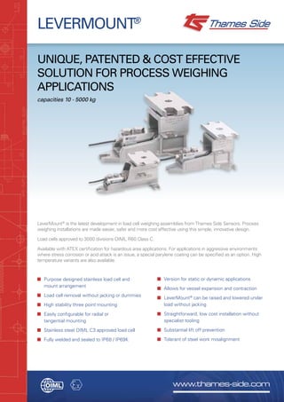
- 1. www.thames-side.com LEVERMOUNT® Unique, patented & cost effective solution for process weighing applications capacities 10 - 5000 kg LeverMount® is the latest development in load cell weighing assemblies from Thames Side Sensors. Process weighing installations are made easier, safer and more cost effective using this simple, innovative design. Load cells approved to 3000 divisions OIML R60 Class C. Available with ATEX certification for hazardous area applications. For applications in aggressive environments where stress corrosion or acid attack is an issue, a special parylene coating can be specified as an option. High temperature variants are also available. ■ Purpose designed stainless load cell and mount arrangement ■ Load cell removal without jacking or dummies ■ High stability three point mounting ■ Easily configurable for radial or tangential mounting ■ Stainless steel OIML C3 approved load cell ■ Fully welded and sealed to IP68 / IP69K ■ Version for static or dynamic applications ■ Allows for vessel expansion and contraction ■ LeverMount® can be raised and lowered under load without jacking ■ Straightforward, low cost installation without specialist tooling ■ Substantial lift off prevention ■ Tolerant of steel work misalignment
- 2. innovation & inspiration... LEVERMOUNT® The concept A purpose designed mounting assembly using single ended shear beam load cells was first introduced in the 1980’s. These designs are still in use today and most provide a threaded jacking feature which allows the vessel to be supported by the mount prior to installation of the load cell, however under most load conditions, an external jack is needed to raise and lower the vessel and the threads can become clogged with dirt or powder, rendering the integral jacking mechanism unusable, even under low loads. LeverMount® is specifically designed to offer a completely fresh approach to process weighing solutions. Utilising the established range of Thames Side shear beam and bending beam load cells, the LeverMount® retains all of the advantages of previous mount designs, whilst providing improved mechanical stability before, during and after installation. LeverMount®’s unique patented design is such that no separate support arrangements are necessary to raise and lower the vessel. The base casting itself provides a stable load bearing platform prior to installation of the load cell. Once the vessel is in position the two transit bolts are removed and the load cell is used as a lever to raise the top plate of the mount into the working position, regardless of whether the vessel is empty or full. Removal of the load cell at any time is accomplished by reversing the procedure and requires no jacks, dummy load cells or specialist tools. Installation, operation and maintenance of the vessel weighing system is consequently made safer, easier, swifter and less costly. Two types of load cell interface can be specified; a load button and saddle arrangement with expansion/contraction adjustment for static applications such as hoppers and tanks and a ball and cup, self-centring, option for dynamic applications such as floor scales. ATEX CERTIFICATION The load cells used in LeverMount® have ATEX certification which allow their use in all dust zones without safety barriers, resulting in significant cost savings. HIGH TEMPERATURE The T66 and 350i load cells used in the LeverMount® are available in high temperature variants which utilise special load cell components and a PTFE ‘Teflon’ cable for operation in environments up to 150°C ENVIRONMENTAL PROTECTION Load cells used in the LeverMount® are rated for both IP68 and IP69K ingress protection as standard. A special parylene coating can be specified as an option to provide additional protectionin extreme environments where stress corrosion could occur, for example where chlorine or acids are present. Code Safety Parameters ApplicationTemp. Class T66 Load Cell 350i Load Cell II 1 GD Ex ia II C T4..T6 Ga IP68 T85˚C Ex ia IIIC T135˚C T85˚C Da Ex ta IIIC T85˚C Da T4 Pi = 2.5W Pi = 1.3W Gas Zones 0, 1, 2 with safety barriers Dust Zones 20, 21, 22 without safety barriers T5 Pi = 2.5W Pi = 0.8W T6 Pi = 1.69W Pi = 0.53W
- 3. www.thames-side.com FEATURES ■ Purpose designed cast 316 grade stainless steel mount ■ Simple two part casting using the transit bolts with captivated nuts for load cell fixing ■ Stainless steel, IP68/IP69K, fully welded, single ended shear beam load cell ■ Load cell acts as a lever to raise and lower the top plate and vessel ■ Vessel can be raised and lowered under load ■ No jacking screws or support pillars ■ Three point support and fixing ■ Top plate movement in the lateral and rotational axis ■ Configurable for radial, tangential or offset mounting ■ Substantial anti-lift facility, over 50% of maximum rated load ■ Minimal difference between the working height and the installed height ■ Load cell can be easily removed under load in situ ■ Three physical sizes cover the range from 10kg to 5000kg BENEFITS ■ Ideal for process weighing applications that require an accurate, safe and cost effective solution ■ Aesthetically pleasing design, eliminating the need for additional machining and special bolts ■ Suitable for use in the harshest of industrial environments ■ No need for alternative lifting devices such as pad jacks ■ Easier, quicker and safer than alternative mount arrangements ■ No stripped threads or top plate interference ■ Eliminates rocking and twisting in the mount, always finds a plane ■ Tolerant of steel work misalignment avoiding any mechanically induced errors ■ Easy alignment to the radial axis of the vessel to compensate for expansion and contraction. ■ Increased safety ■ Reduces the need to adjust for pipe work without flexible connections ■ Less down time ■ Covers the majority of process weighing applications
- 4. Our policy is one of continuous product enhancement. We therefore reserve the right to incorporate technical modifications without prior notification. DISTRIBUTED BY: www.thames-side.com Thames Side Sensors Ltd Unit 10, io Trade Centre, Deacon Way, Reading, Berkshire RG30 6AZ tel: +44 (0) 118 941 1387 fax: +44 (0) 118 941 2004 sales@thames-side.co.uk www.thames-side.com Issue: Levermount.07.13 Load cell specification Units LeverMount Lite LeverMount Load Cell Approval 3000 divisions (C3) OIML R60 Class C 3000 divisions (C3) OIML R60 Class C Load Ranges 10, 20, 50,100, 150, 200 300, 500, 1000, 2000, 3000 5000 kg Rated Output 2+/- 0.1% 2±0.15% mV/V Combined Error ±0.017 ±0.017 %* Non-repeatability ±0.015 ±0.015 %* Creep (30 minutes) ±0.016 ±0.016 %* Temp Effect on Zero Balance ±0.002 ±0.002 %*/˚C Temp Effect on Span ±0.0012 ±0.0012 %*/˚C Compensated Temp Range -10 to +40 -10 to +40 ˚C Operating Temp Range -20 to +70 -20 to +70 ˚C Safe Overload 150 150 %* Ultimate Overload 300 300 %* Zero Balance ±1 ±2 %* Input Resistance 400 400 Ω ± 20 Output Resistance 350 350 Ω ± 3 Insulation Resistance 5000 5000 MΩ @ 100v.dc Recommended Supply Voltage 10 10 V Maximum Supply Voltage 15 15 V Cable Length 3 5 m Cable Material Polyurethane Polyurethane Protection Class IP68 / IP69K IP68 / IP69K *With respect to rated output + ve input RED + ve output GREEN - ve input BLUE - ve output YELLOW Electrical Connections Via 4 core, 5.7mm diameter, screened polyurethane cable. Screen not connected electrically to load cell. Shipping Weights: (kg) 10, 20, 50, 100, 150, 200 = 1.2kg 300, 500, 1000, 2000 = 4kg 3000, 5000 = 9kg Construction Mount manufactured from cast 316 stainless steel. Load cell manufactured from high strength 17-4PH stainless steel. UK Patent No. 2 339 026 US Patent No. 6 320 142 LeverMount® is a registered trademark of Thames Side Sensors Limited. technical specification... LEVERMOUNT® Capacity (kg) A B C D E F G H J K L M 20, 50, 100, 200 70 16 147 100 80 9 55 9 19 80 7 8 300, 500, 1000, 2000 70 16 168 132 108 14 60 14 19 110 12 12 3000, 5000 100 25 225 190 150 22 80 22 25 164 15 20 All dimensions in mm.