SlideShare une entreprise Scribd logo
1  sur  12
Télécharger pour lire hors ligne
Safety Precautions
1
Always observe safety precautions whenever working on a vehicle.
DO NOT wear loose clothing, watches, rings or other jewelry when working on a vehicle.
Always wear safety eye protection.
Only work on a vehicle in a well-ventilated area.
Put transmission in “park” (for automatic) or “neutral” (for manual). Set parking brake. Put
blocks on drive wheels.
Avoid moving fan blades or any potentially moving parts. WHEN USING THE TIMING
LIGHT, THESE PARTS MAY APPEAR TO BE STOPPED OR MOVING SLOWLY.
Avoid hot engine parts.
The vehicle battery produces explosive gases. DO NOT smoke or allow spark or flame
near the battery.
BE CAREFUL when working near high-voltage parts (spark plugs or coil terminals).
Turn off ignition before connecting (or disconnecting) any testing equipment.
ALWAYS READ THE VEHICLE'S SERVICE MANUAL BEFORE PERFORMING ANY
PROCEDURE. OBSERVE ALL SAFETY PRECAUTIONS.
NOTE
EMI/RFI problems with Digital Timing Lights:
If the Digital Timing Light readout becomes inoperative or locks up during use,
disconnect and reconnect the timing light's positive battery clip from the battery to
reset the unit.
Some aftermarket ignition systems and/or specialty spark plug wires (solid core
wires, racing wires, off-road wires) radiate above normal Electro-Magnetic
Interference (EMI) and Radio Frequency Interference (RFI) which can cause
improper operation of testing equipment. Please contact these manufacturers for
instructions on how to use an inductive pickup with their systems.
It may be necessary to replace the No. 1 spark plug wire with an O. E.-style plug wire
during testing.
General Information
2
ABOUT THE TIMING LIGHT
This timing light is designed for use with all 12-volt negative-ground vehicles. The timing
light may also be used on vehicles equipped with DIS (distributorless ignition systems).
Operating Controls and Indicators — General (see Figure 1)
1. Xenon Bulb — Used to illuminate timing marks for checking timing.
2. Swiveling Head — Contains the xenon bulb. Rotates over approximately 90° to allow
for easy illumination of timing marks in hard to reach locations.
3. Control Panel — Contains the controls and indicators necessary to operate the timing
light.
4. Inductive Pickup Leads — Detachable leads assembly connects timing light to the
battery and ignition system:
Red Battery Clip — Connects to battery positive (+) terminal.
Black Battery Clip — Connects to battery negative (-) terminal or bare metal
chassis ground.
Inductive Pickup Clip — Clamps around No. 1 spark plug cable.
Green DWELL Clip — Connects to the negative (tach) side of the ignition coil.
Control Panel Controls and Indicators (see Figure 2)
1. Flash Switch — Push to turn strobe light on. Push again to turn strobe light off.
2. LCD Display — Provides a digital display of engine operating parameters including
engine speed (rpm), advance (degrees), dwell angle (degrees), and battery and
charging system voltage. Displayed information depends on operating mode selected.
LCD display is backlit in soft blue light for easy viewing in low-light areas.
F
T
A
C
H
DW
EL
L
CY
LIND
ER
AD
VA
NC
E
+
-
1
2
3 4
Figure 1. Operating Controls and Indicators
General Information
3
BATTERY VOLTAGE MODE
11
13
14
ADVANCE MODE
9
19 15
16
4
VOLTAGE/RPM MODE
13
4
1615
12
DWELL MODE
8
1817
1
3
10
7
2
5
6
10
Figure 2. Control Panel Controls and Indicators
General Information
4
3. Function (F) Switch — Selects timing light operating mode (voltage/rpm, advance or
dwell).
4. RPM Indicator — Displays when 2-cycle (DIS) or 4-cycle rpm mode is selected.
5. Cylinder/Advance Increment Switch
Dwell Mode — Increments through available cylinder settings for dwell check.
Enabled when dwell mode is selected.
Advance Mode — Increments through degrees of advance. Enabled when
advance mode is selected.
6. Cylinder/Advance Decrement Switch
Dwell Mode — Decrements through available cylinder settings for dwell check.
Enabled when dwell mode is selected.
Advance Mode — Decrements through degrees of advance. Enabled when
advance mode is selected.
7. Zeroing Switch — Returns LCD advance degrees to zero. Enabled when advance
mode is selected.
8. DWELL Indicator — Displays when dwell mode is selected. LCD display shows dwell
angle and number of cylinders.
9. ADVANCE Indicator — Displays when advance mode is selected. LCD display shows
degrees advance and engine rpm.
10. Ignition System Selection — Selects the timing light operating mode (either 2-cycle
(DIS) or 4-cycle) by pressing BOTH the Function (F) switch and the Cylinder/Advance
Decrement switch simultaneously.
11. Battery VOLTS Indicator — Displays when battery voltage mode is selected. LCD
display shows battery voltage.
12. Charging System Battery VOLTS Indicator — Displays when voltage/rpm mode is
selected. LCD display shows charging system battery voltage and engine rpm.
13. Volt Symbol — Displays when voltage modes are selected.
14. Battery Symbol — Displays when battery voltage mode is selected.
15. Flash Symbol — Blinks when strobe light is operating.
16. Ignition Mode Symbol — Displays ignition system selected.
17. Cylinder Symbol — Displays when dwell mode is selected.
18. Dwell Angle Symbol — Displays when dwell mode is selected.
19. Advance Degree Symbol — Displays when advance mode is selected.
OPERATING SPECIFICATIONS
Power Requirements: 10 to 16 volts DC
Operating Temperature: 32 to 122°F (0 to 50°C)
Tachometer Range: 240 to 9,990 RPM
Timing Advance Range: 0 to +90°
Operation
5
APPLICATIONS
This timing light is designed for use on most late model import or domestic vehicles
equipped with conventional or electronic ignition systems, or with DIS (distributorless
ignition systems).
TIMING LIGHT CONNECTION
WARNING: Always keep hands, timing light, lead wires and clips away from moving
engine parts and hot surfaces. DO NOT SMOKE.
1. Turn ignition off. DO NOT CONNECT TIMING LIGHT WITH IGNITION ON OR
ENGINE RUNNING.
2. Clamp inductive pickup clip around No. 1 spark plug wire (arrow points toward spark plug).
3. Connect the green DWELL clip to the negative (tach) side of the ignition coil (if applicable).
4. Connect battery clips to battery:
Connect RED clip to battery positive (+) terminal.
Connect BLACK clip to battery negative (-) terminal or chassis ground.
5. Attach pickup leads into bottom of timing light handle.
VOLTMETER OPERATION
Make sure timing light is properly connected as described in TIMING LIGHT CONNECTION.
ALWAYS check battery and charging system voltage before performing timing check to
ensure reliable results.
1. With timing light connected and engine off, timing light is in battery voltage mode; the
Battery VOLTS indicator, Volts symbol and Battery symbol will display. The LCD
display will show battery voltage.
2. When the engine is started, the timing light enters the voltage/rpm mode; the Charging
System Battery VOLTS indicator, Volts symbol and Ignition Mode symbol (either 2-
cycle (DIS) or 4-cycle) will display. The LCD display will show charging system voltage
and engine rpm.
CHECKING DWELL ANGLE
Dwell angle check is performed for vehicles equipped with conventional or electronic
ignition systems.
Make sure timing light is properly connected as described in TIMING LIGHT
CONNECTION.
1. Start and run engine until it reaches normal operating temperature.
2. Press Function (F) switch as needed to select dwell mode. The DWELL Indicator,
Cylinder Symbol, and Dwell Angle Symbol will display when dwell mode is selected.
Press Cylinder/Advance Increment and Decrement switches as needed to select
appropriate number of cylinders for vehicle under test. The LCD display will show
the number of cylinders selected and the dwell angle.
Operation
6
3. Note dwell angle and compare to manufacturer's specifications.
4. Refer to the vehicle's service manual for procedures to adjust dwell angle.
5. Turn ignition off and disconnect timing light from engine.
INITIAL TIMING CHECK (USING NO. 1 CYLINDER)
ALWAYS refer to the manufacturer's test procedures and specifications when
performing timing check. Timing procedures vary from vehicle to vehicle. Refer to the
Vehicle Emission Control Label or service manual for the vehicle under test.
Some vehicles equipped with computerized engine control systems may be
designated as "NON-ADJUSTABLE".
Make sure timing light is properly connected as described in TIMING LIGHT CONNECTION.
MAKE SURE the proper operating mode is selected (2- cycle (DIS) or 4-cycle).
If vehicle is equipped with distributor points, check dwell as described in CHECKING
DWELL ANGLE, and adjust if necessary BEFORE performing timing check.
1. Start and run engine until it reaches normal operating temperature.
The Flash Indicator will blink to indicate the timing light is operating.
Press both ignition system selection switches SIMULTANEOUSLY to select either 2-
cycle (DIS) or 4-cycle mode. The Ignition Mode Symbol will display the selected mode.
Press Function (F) switch as needed to select voltage/rpm mode. The RPM
Indicator will display when voltage/rpm mode is selected. The LCD display will show
engine rpm. Adjust engine rpm as necessary.
2. Adjust timing light barrel, as needed, to ensure proper illumination of timing marks.
3. Refer to the vehicle's service manual to check and adjust timing. OBSERVE ALL
SAFETY PRECAUTIONS.
4. Press Flash switch. Timing light will stop flashing.
5. Turn ignition off and disconnect timing light from engine.
6. If disconnected, reconnect vacuum line to distributor.
ADVANCE/RETARD TIMING CONTROL CHECKS
Advance and retard timing controls ensure that ignition occurs at the proper time during the
compression stroke. These controls include mechanical advance, vacuum advance,
vacuum retard, electronic advance, electronic retard, and electronic advance/retard.
Depending on make and model, a vehicle may be equipped with a single timing control
device, or two or more devices may be used in combination.
Advance and retard timing test procedures vary widely from vehicle to vehicle.
The following paragraphs provide general test procedures for checking
mechanical advance, mechanical/vacuum advance, and vacuum retard. ALWAYS
make sure initial timing and dwell are correct before checking advance/retard
timing. ALWAYS refer to the service manual for the vehicle under test to obtain
the proper timing procedures and specifications. OBSERVE ALL SAFETY
PRECAUTIONS.
Operation
7
Centrifugal/Mechanical Advance
Make sure timing light is properly connected as described in TIMING LIGHT
CONNECTION.
Make sure initial timing is correct. If necessary, prepare engine for advance timing
check as directed by manufacturer's instructions.
1. With timing light directed at timing marks, note position of rotating timing mark in
relation to reference pointer. Reading should indicate initial timing in accordance with
manufacturer's specifications.
2. Adjust engine speed to the specified RPM for advance test.
3. Press Function (F) switch as needed to select advance mode. The ADVANCE indicator
and Advance Degree symbol will display when advance mode is selected. The LCD
display will show "0" degrees advance and engine rpm.
4. With timing light directed at timing marks, press Cylinder/Advance Increment switch as
needed to realign timing marks to initial timing or as instructed by manufacturer's
specifications. Note degrees advance on LCD display and compare with manufacturer's
specifications.
5. Turn off ignition and disconnect timing light from engine.
Vacuum Advance
Make sure timing light is properly connected as described in TIMING LIGHT
CONNECTION.
Make sure initial timing is correct. If necessary, prepare engine for advance timing
check as directed by manufacturer's instructions.
A vacuum pump equipped with a vacuum gauge is needed to check vacuum
advance.
1. With engine off, disconnect vacuum hose from distributor's vacuum advance port; plug
vacuum hose.
2. Connect vacuum pump to distributor's vacuum advance port.
3. Start and run engine until it reaches normal operating temperature.
4. Press Function (F) switch as needed to select advance mode. The ADVANCE indicator
and Advance Degree symbol will display when advance mode is selected. The LCD
display will show "0" degrees advance and engine rpm.
5. With timing light directed at timing marks, note position of rotating timing mark in
relation to reference pointer. Reading should indicate initial timing in accordance with
manufacturer's specifications.
6. Using vacuum pump, apply specified amount of vacuum to distributor's vacuum port.
7. With timing light directed at timing marks, press Cylinder/Advance Increment switch as
needed to realign timing marks to initial timing. Note degrees advance on LCD display
and compare with manufacturer's specifications.
8. Turn off ignition and disconnect timing light from engine. Unplug and reconnect vacuum
hose to distributor's vacuum port.
Operation
8
Electronic Advance/Retard
Refer to manufacturer's instructions for procedures to check electronic advance/retard. For
some systems, it may be necessary to set the timing light's advance display to "0" and to
read timing from the vehicle's timing marks.
TIMING ADJUSTMENT
Refer to the vehicle’s service manual for procedures to adjust timing. DO NOT ATTEMPT
TO ADJUST TIMING WITHOUT MANUFACTURER’S SPECIFICATIONS.
TROUBLESHOOTING
If the timing light readout becomes inoperative or locks up during use, disconnect
and reconnect the timing light's positive battery clamp from the battery to reset the
unit.
If the timing light fails to operate, make the following checks:
1. Make sure the battery clips are firmly connected to the battery terminals.
2. Make sure the battery clip polarity is correct (red clip to positive terminal, black clip to
negative terminal).
3. Make sure the upper and lower ferrite cores of the inductive pickup clip are clean.
Clean the inductive pickup clip if necessary (see Maintenance on page 9).
4. Make sure the inductive pickup clip is properly connected to the No. 1 spark plug cable.
5. Make sure the No. 1 spark plug is working properly:
Connect the inductive pickup clip to another spark plug cable.
If the timing light flashes, service the No. 1 spark plug before continuing.
Maintenance
9
CLEANING THE INDUCTIVE PICKUP CLIP
Dirt or grease on the inside surfaces of the inductive pickup clip can result in erratic flashing
or poor operation of the timing light. Periodically clean the contact surfaces inside the
inductive pickup clip by wiping with a soft cloth.
REPLACING THE INDUCTIVE PICKUP LEADS
The timing light is equipped with detachable leads which can be disconnected from the
timing light for easy storage after use. If the test leads or clips become damaged, a
replacement set can be obtained from your dealer or directly from the service center.
Notes
10
Notes
11
Notes
12

Contenu connexe

Tendances

Plc example presentation
Plc example presentationPlc example presentation
Plc example presentation
Roshit Kadiru
 

Tendances (20)

PLC General
PLC   GeneralPLC   General
PLC General
 
Summer Training Program Report On Embedded system and robot
Summer Training Program Report On Embedded system and robot Summer Training Program Report On Embedded system and robot
Summer Training Program Report On Embedded system and robot
 
RTC Interfacing and Programming
RTC Interfacing and ProgrammingRTC Interfacing and Programming
RTC Interfacing and Programming
 
An Introduction to Robotics and Embedded System
An Introduction to Robotics and Embedded SystemAn Introduction to Robotics and Embedded System
An Introduction to Robotics and Embedded System
 
Schematics_88750_1_12M14.pdf
Schematics_88750_1_12M14.pdfSchematics_88750_1_12M14.pdf
Schematics_88750_1_12M14.pdf
 
programmable logic controller presentation
programmable logic controller presentationprogrammable logic controller presentation
programmable logic controller presentation
 
Programming logic controllers (plc) seminar
Programming  logic controllers (plc) seminarProgramming  logic controllers (plc) seminar
Programming logic controllers (plc) seminar
 
Plc example presentation
Plc example presentationPlc example presentation
Plc example presentation
 
Serial Communication Interfaces
Serial Communication InterfacesSerial Communication Interfaces
Serial Communication Interfaces
 
Plc
PlcPlc
Plc
 
VLSI VHDL
VLSI VHDLVLSI VHDL
VLSI VHDL
 
Lin protocol
Lin protocolLin protocol
Lin protocol
 
Introduction to MPLAB IDE
Introduction to MPLAB IDEIntroduction to MPLAB IDE
Introduction to MPLAB IDE
 
PLC Brief
PLC BriefPLC Brief
PLC Brief
 
Micro sd specification
Micro sd specificationMicro sd specification
Micro sd specification
 
Lin bus
Lin busLin bus
Lin bus
 
Programmable Logic Controller
Programmable Logic ControllerProgrammable Logic Controller
Programmable Logic Controller
 
Test Bench Development
Test Bench DevelopmentTest Bench Development
Test Bench Development
 
Plc seminar abu
Plc seminar    abuPlc seminar    abu
Plc seminar abu
 
Profibus
ProfibusProfibus
Profibus
 

Similaire à Innova 5568 Pro-Timing Light User Manual

02 th!nk neighbor
02 th!nk neighbor02 th!nk neighbor
02 th!nk neighbor
rukford
 
98 mark viii
98 mark viii98 mark viii
98 mark viii
rukford1
 
00 villager
00 villager00 villager
00 villager
rukford1
 
98 e150 250-350-450
98 e150 250-350-45098 e150 250-350-450
98 e150 250-350-450
rukford1
 
01 villager
01 villager01 villager
01 villager
rukford
 
00 postal explorer
00 postal explorer00 postal explorer
00 postal explorer
rukford1
 
98 grand marquis
98 grand marquis98 grand marquis
98 grand marquis
rukford1
 
98 mustang
98 mustang98 mustang
98 mustang
rukford1
 
00 mustang
00 mustang00 mustang
00 mustang
rukford1
 
01 postal explorer
01 postal explorer01 postal explorer
01 postal explorer
rukford
 
98 mystique
98 mystique98 mystique
98 mystique
rukford1
 

Similaire à Innova 5568 Pro-Timing Light User Manual (20)

Actron CP7529 Digital Timing Light User Manual
Actron CP7529 Digital Timing Light User ManualActron CP7529 Digital Timing Light User Manual
Actron CP7529 Digital Timing Light User Manual
 
Actron CP7527 Inductive Timing Light User Manual
Actron CP7527 Inductive Timing Light User ManualActron CP7527 Inductive Timing Light User Manual
Actron CP7527 Inductive Timing Light User Manual
 
Actron CP7528 Advance Timing Light User Manual
Actron CP7528 Advance Timing Light User ManualActron CP7528 Advance Timing Light User Manual
Actron CP7528 Advance Timing Light User Manual
 
02 th!nk neighbor
02 th!nk neighbor02 th!nk neighbor
02 th!nk neighbor
 
Innova 3551 Inductive Timing Light User Manual
Innova 3551 Inductive Timing Light User ManualInnova 3551 Inductive Timing Light User Manual
Innova 3551 Inductive Timing Light User Manual
 
Innova 3555 Advance Timing Light User Manual
Innova 3555 Advance Timing Light User ManualInnova 3555 Advance Timing Light User Manual
Innova 3555 Advance Timing Light User Manual
 
Innova 3568 Digital Timing Light User Manual
Innova 3568 Digital Timing Light User ManualInnova 3568 Digital Timing Light User Manual
Innova 3568 Digital Timing Light User Manual
 
98 mark viii
98 mark viii98 mark viii
98 mark viii
 
00 villager
00 villager00 villager
00 villager
 
98 e150 250-350-450
98 e150 250-350-45098 e150 250-350-450
98 e150 250-350-450
 
98 ranger
98 ranger98 ranger
98 ranger
 
98 sable
98 sable98 sable
98 sable
 
01 villager
01 villager01 villager
01 villager
 
00 postal explorer
00 postal explorer00 postal explorer
00 postal explorer
 
98 grand marquis
98 grand marquis98 grand marquis
98 grand marquis
 
98 mustang
98 mustang98 mustang
98 mustang
 
00 mustang
00 mustang00 mustang
00 mustang
 
01 postal explorer
01 postal explorer01 postal explorer
01 postal explorer
 
98 mystique
98 mystique98 mystique
98 mystique
 
Manual supra carrier
Manual supra carrierManual supra carrier
Manual supra carrier
 

Plus de Tim Miller

Plus de Tim Miller (20)

Mazda Dashboard Warning Lights: Symbols and Meanings [FULL LIST]
Mazda Dashboard Warning Lights: Symbols and Meanings [FULL LIST]Mazda Dashboard Warning Lights: Symbols and Meanings [FULL LIST]
Mazda Dashboard Warning Lights: Symbols and Meanings [FULL LIST]
 
Mini Cooper Dashboard Warning Lights: Symbols and Meanings [FULL LIST]
Mini Cooper Dashboard Warning Lights: Symbols and Meanings [FULL LIST]Mini Cooper Dashboard Warning Lights: Symbols and Meanings [FULL LIST]
Mini Cooper Dashboard Warning Lights: Symbols and Meanings [FULL LIST]
 
Mack Trucks' Body Builder Instructions
Mack Trucks' Body Builder InstructionsMack Trucks' Body Builder Instructions
Mack Trucks' Body Builder Instructions
 
Kenworth W900 Heavy Duty Body Builder Manual
Kenworth W900 Heavy Duty Body Builder ManualKenworth W900 Heavy Duty Body Builder Manual
Kenworth W900 Heavy Duty Body Builder Manual
 
Massey Ferguson Global Series Product Book
Massey Ferguson Global Series Product BookMassey Ferguson Global Series Product Book
Massey Ferguson Global Series Product Book
 
Ancel DS700 User's Manual
Ancel DS700 User's ManualAncel DS700 User's Manual
Ancel DS700 User's Manual
 
Dodge, Jeep, and Chrysler OBD1 Code List (PDF)
Dodge, Jeep, and Chrysler OBD1 Code List (PDF)Dodge, Jeep, and Chrysler OBD1 Code List (PDF)
Dodge, Jeep, and Chrysler OBD1 Code List (PDF)
 
Honda/ Acura OBD1 Code List (PDF)
Honda/ Acura OBD1 Code List (PDF)Honda/ Acura OBD1 Code List (PDF)
Honda/ Acura OBD1 Code List (PDF)
 
Honda/ Acura OBD2 Code List (PDF)
Honda/ Acura OBD2 Code List (PDF)Honda/ Acura OBD2 Code List (PDF)
Honda/ Acura OBD2 Code List (PDF)
 
GM OBD2 Code List (PDF)
GM OBD2 Code List (PDF)GM OBD2 Code List (PDF)
GM OBD2 Code List (PDF)
 
GM OBD1 Code List (PDF)
GM OBD1 Code List (PDF)GM OBD1 Code List (PDF)
GM OBD1 Code List (PDF)
 
Toyota Dashboard Warning Lights [FULL]
Toyota Dashboard Warning Lights [FULL]Toyota Dashboard Warning Lights [FULL]
Toyota Dashboard Warning Lights [FULL]
 
ThinkOBD 500 User's Manual
ThinkOBD 500 User's ManualThinkOBD 500 User's Manual
ThinkOBD 500 User's Manual
 
Ancel V6 User's Manual
Ancel V6 User's ManualAncel V6 User's Manual
Ancel V6 User's Manual
 
GM OBD1 Code List (PDF)
GM OBD1 Code List (PDF)GM OBD1 Code List (PDF)
GM OBD1 Code List (PDF)
 
Ford OBD1 Code List (PDF)
Ford OBD1 Code List (PDF)Ford OBD1 Code List (PDF)
Ford OBD1 Code List (PDF)
 
GM OBD1 Code List (PDF)
GM OBD1 Code List (PDF)GM OBD1 Code List (PDF)
GM OBD1 Code List (PDF)
 
GM OBD2 Code List (PDF)
GM OBD2 Code List (PDF)GM OBD2 Code List (PDF)
GM OBD2 Code List (PDF)
 
Ford OBD2 Code List (PDF)
Ford OBD2 Code List (PDF)Ford OBD2 Code List (PDF)
Ford OBD2 Code List (PDF)
 
Thinkscan User's Manual
Thinkscan User's ManualThinkscan User's Manual
Thinkscan User's Manual
 

Dernier

FULL NIGHT — 9999894380 Call Girls In Jagat Puri | Delhi
FULL NIGHT — 9999894380 Call Girls In Jagat Puri | DelhiFULL NIGHT — 9999894380 Call Girls In Jagat Puri | Delhi
FULL NIGHT — 9999894380 Call Girls In Jagat Puri | Delhi
SaketCallGirlsCallUs
 
➥🔝 7737669865 🔝▻ Bhiwandi Call-girls in Women Seeking Men 🔝Bhiwandi🔝 Escor...
➥🔝 7737669865 🔝▻ Bhiwandi Call-girls in Women Seeking Men  🔝Bhiwandi🔝   Escor...➥🔝 7737669865 🔝▻ Bhiwandi Call-girls in Women Seeking Men  🔝Bhiwandi🔝   Escor...
➥🔝 7737669865 🔝▻ Bhiwandi Call-girls in Women Seeking Men 🔝Bhiwandi🔝 Escor...
amitlee9823
 
Vip Mumbai Call Girls Mira Road Call On 9920725232 With Body to body massage ...
Vip Mumbai Call Girls Mira Road Call On 9920725232 With Body to body massage ...Vip Mumbai Call Girls Mira Road Call On 9920725232 With Body to body massage ...
Vip Mumbai Call Girls Mira Road Call On 9920725232 With Body to body massage ...
amitlee9823
 
+971565801893>>SAFE AND ORIGINAL ABORTION PILLS FOR SALE IN ABUDHABI,DUBAI MA...
+971565801893>>SAFE AND ORIGINAL ABORTION PILLS FOR SALE IN ABUDHABI,DUBAI MA...+971565801893>>SAFE AND ORIGINAL ABORTION PILLS FOR SALE IN ABUDHABI,DUBAI MA...
+971565801893>>SAFE AND ORIGINAL ABORTION PILLS FOR SALE IN ABUDHABI,DUBAI MA...
Health
 
Top Rated Call Girls Vashi : 9920725232 We offer Beautiful and sexy Call Girl...
Top Rated Call Girls Vashi : 9920725232 We offer Beautiful and sexy Call Girl...Top Rated Call Girls Vashi : 9920725232 We offer Beautiful and sexy Call Girl...
Top Rated Call Girls Vashi : 9920725232 We offer Beautiful and sexy Call Girl...
amitlee9823
 
Call Girls Kanakapura Road Just Call 👗 7737669865 👗 Top Class Call Girl Servi...
Call Girls Kanakapura Road Just Call 👗 7737669865 👗 Top Class Call Girl Servi...Call Girls Kanakapura Road Just Call 👗 7737669865 👗 Top Class Call Girl Servi...
Call Girls Kanakapura Road Just Call 👗 7737669865 👗 Top Class Call Girl Servi...
amitlee9823
 
如何办理麦考瑞大学毕业证(MQU毕业证书)成绩单原版一比一
如何办理麦考瑞大学毕业证(MQU毕业证书)成绩单原版一比一如何办理麦考瑞大学毕业证(MQU毕业证书)成绩单原版一比一
如何办理麦考瑞大学毕业证(MQU毕业证书)成绩单原版一比一
ozave
 
一比一原版(PU学位证书)普渡大学毕业证学历认证加急办理
一比一原版(PU学位证书)普渡大学毕业证学历认证加急办理一比一原版(PU学位证书)普渡大学毕业证学历认证加急办理
一比一原版(PU学位证书)普渡大学毕业证学历认证加急办理
ezgenuh
 
一比一原版(UdeM学位证书)蒙特利尔大学毕业证学历认证怎样办
一比一原版(UdeM学位证书)蒙特利尔大学毕业证学历认证怎样办一比一原版(UdeM学位证书)蒙特利尔大学毕业证学历认证怎样办
一比一原版(UdeM学位证书)蒙特利尔大学毕业证学历认证怎样办
ezgenuh
 
83778-77756 ( HER.SELF ) Brings Call Girls In Laxmi Nagar
83778-77756 ( HER.SELF ) Brings Call Girls In Laxmi Nagar83778-77756 ( HER.SELF ) Brings Call Girls In Laxmi Nagar
83778-77756 ( HER.SELF ) Brings Call Girls In Laxmi Nagar
dollysharma2066
 
Top Rated Call Girls Mumbai Central : 9920725232 We offer Beautiful and sexy ...
Top Rated Call Girls Mumbai Central : 9920725232 We offer Beautiful and sexy ...Top Rated Call Girls Mumbai Central : 9920725232 We offer Beautiful and sexy ...
Top Rated Call Girls Mumbai Central : 9920725232 We offer Beautiful and sexy ...
amitlee9823
 
Call Girls Bangalore Just Call 👗 7737669865 👗 Top Class Call Girl Service Ban...
Call Girls Bangalore Just Call 👗 7737669865 👗 Top Class Call Girl Service Ban...Call Girls Bangalore Just Call 👗 7737669865 👗 Top Class Call Girl Service Ban...
Call Girls Bangalore Just Call 👗 7737669865 👗 Top Class Call Girl Service Ban...
amitlee9823
 

Dernier (20)

John deere 425 445 455 Maitenance Manual
John deere 425 445 455 Maitenance ManualJohn deere 425 445 455 Maitenance Manual
John deere 425 445 455 Maitenance Manual
 
(INDIRA) Call Girl Surat Call Now 8250077686 Surat Escorts 24x7
(INDIRA) Call Girl Surat Call Now 8250077686 Surat Escorts 24x7(INDIRA) Call Girl Surat Call Now 8250077686 Surat Escorts 24x7
(INDIRA) Call Girl Surat Call Now 8250077686 Surat Escorts 24x7
 
FULL NIGHT — 9999894380 Call Girls In Jagat Puri | Delhi
FULL NIGHT — 9999894380 Call Girls In Jagat Puri | DelhiFULL NIGHT — 9999894380 Call Girls In Jagat Puri | Delhi
FULL NIGHT — 9999894380 Call Girls In Jagat Puri | Delhi
 
How To Troubleshoot Mercedes Blind Spot Assist Inoperative Error
How To Troubleshoot Mercedes Blind Spot Assist Inoperative ErrorHow To Troubleshoot Mercedes Blind Spot Assist Inoperative Error
How To Troubleshoot Mercedes Blind Spot Assist Inoperative Error
 
➥🔝 7737669865 🔝▻ Bhiwandi Call-girls in Women Seeking Men 🔝Bhiwandi🔝 Escor...
➥🔝 7737669865 🔝▻ Bhiwandi Call-girls in Women Seeking Men  🔝Bhiwandi🔝   Escor...➥🔝 7737669865 🔝▻ Bhiwandi Call-girls in Women Seeking Men  🔝Bhiwandi🔝   Escor...
➥🔝 7737669865 🔝▻ Bhiwandi Call-girls in Women Seeking Men 🔝Bhiwandi🔝 Escor...
 
Vip Mumbai Call Girls Mira Road Call On 9920725232 With Body to body massage ...
Vip Mumbai Call Girls Mira Road Call On 9920725232 With Body to body massage ...Vip Mumbai Call Girls Mira Road Call On 9920725232 With Body to body massage ...
Vip Mumbai Call Girls Mira Road Call On 9920725232 With Body to body massage ...
 
What Does The Engine Malfunction Reduced Power Message Mean For Your BMW X5
What Does The Engine Malfunction Reduced Power Message Mean For Your BMW X5What Does The Engine Malfunction Reduced Power Message Mean For Your BMW X5
What Does The Engine Malfunction Reduced Power Message Mean For Your BMW X5
 
+971565801893>>SAFE AND ORIGINAL ABORTION PILLS FOR SALE IN ABUDHABI,DUBAI MA...
+971565801893>>SAFE AND ORIGINAL ABORTION PILLS FOR SALE IN ABUDHABI,DUBAI MA...+971565801893>>SAFE AND ORIGINAL ABORTION PILLS FOR SALE IN ABUDHABI,DUBAI MA...
+971565801893>>SAFE AND ORIGINAL ABORTION PILLS FOR SALE IN ABUDHABI,DUBAI MA...
 
Top Rated Call Girls Vashi : 9920725232 We offer Beautiful and sexy Call Girl...
Top Rated Call Girls Vashi : 9920725232 We offer Beautiful and sexy Call Girl...Top Rated Call Girls Vashi : 9920725232 We offer Beautiful and sexy Call Girl...
Top Rated Call Girls Vashi : 9920725232 We offer Beautiful and sexy Call Girl...
 
Call Girls Kanakapura Road Just Call 👗 7737669865 👗 Top Class Call Girl Servi...
Call Girls Kanakapura Road Just Call 👗 7737669865 👗 Top Class Call Girl Servi...Call Girls Kanakapura Road Just Call 👗 7737669865 👗 Top Class Call Girl Servi...
Call Girls Kanakapura Road Just Call 👗 7737669865 👗 Top Class Call Girl Servi...
 
Lecture-20 Kleene’s Theorem-1.pptx best for understanding the automata
Lecture-20 Kleene’s Theorem-1.pptx best for understanding the automataLecture-20 Kleene’s Theorem-1.pptx best for understanding the automata
Lecture-20 Kleene’s Theorem-1.pptx best for understanding the automata
 
如何办理麦考瑞大学毕业证(MQU毕业证书)成绩单原版一比一
如何办理麦考瑞大学毕业证(MQU毕业证书)成绩单原版一比一如何办理麦考瑞大学毕业证(MQU毕业证书)成绩单原版一比一
如何办理麦考瑞大学毕业证(MQU毕业证书)成绩单原版一比一
 
一比一原版(PU学位证书)普渡大学毕业证学历认证加急办理
一比一原版(PU学位证书)普渡大学毕业证学历认证加急办理一比一原版(PU学位证书)普渡大学毕业证学历认证加急办理
一比一原版(PU学位证书)普渡大学毕业证学历认证加急办理
 
John Deere 335 375 385 435 Service Repair Manual
John Deere 335 375 385 435 Service Repair ManualJohn Deere 335 375 385 435 Service Repair Manual
John Deere 335 375 385 435 Service Repair Manual
 
一比一原版(UdeM学位证书)蒙特利尔大学毕业证学历认证怎样办
一比一原版(UdeM学位证书)蒙特利尔大学毕业证学历认证怎样办一比一原版(UdeM学位证书)蒙特利尔大学毕业证学历认证怎样办
一比一原版(UdeM学位证书)蒙特利尔大学毕业证学历认证怎样办
 
83778-77756 ( HER.SELF ) Brings Call Girls In Laxmi Nagar
83778-77756 ( HER.SELF ) Brings Call Girls In Laxmi Nagar83778-77756 ( HER.SELF ) Brings Call Girls In Laxmi Nagar
83778-77756 ( HER.SELF ) Brings Call Girls In Laxmi Nagar
 
Connaught Place, Delhi Call girls :8448380779 Model Escorts | 100% verified
Connaught Place, Delhi Call girls :8448380779 Model Escorts | 100% verifiedConnaught Place, Delhi Call girls :8448380779 Model Escorts | 100% verified
Connaught Place, Delhi Call girls :8448380779 Model Escorts | 100% verified
 
Stay Cool and Compliant: Know Your Window Tint Laws Before You Tint
Stay Cool and Compliant: Know Your Window Tint Laws Before You TintStay Cool and Compliant: Know Your Window Tint Laws Before You Tint
Stay Cool and Compliant: Know Your Window Tint Laws Before You Tint
 
Top Rated Call Girls Mumbai Central : 9920725232 We offer Beautiful and sexy ...
Top Rated Call Girls Mumbai Central : 9920725232 We offer Beautiful and sexy ...Top Rated Call Girls Mumbai Central : 9920725232 We offer Beautiful and sexy ...
Top Rated Call Girls Mumbai Central : 9920725232 We offer Beautiful and sexy ...
 
Call Girls Bangalore Just Call 👗 7737669865 👗 Top Class Call Girl Service Ban...
Call Girls Bangalore Just Call 👗 7737669865 👗 Top Class Call Girl Service Ban...Call Girls Bangalore Just Call 👗 7737669865 👗 Top Class Call Girl Service Ban...
Call Girls Bangalore Just Call 👗 7737669865 👗 Top Class Call Girl Service Ban...
 

Innova 5568 Pro-Timing Light User Manual

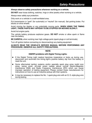
  • 1. Safety Precautions 1 Always observe safety precautions whenever working on a vehicle. DO NOT wear loose clothing, watches, rings or other jewelry when working on a vehicle. Always wear safety eye protection. Only work on a vehicle in a well-ventilated area. Put transmission in “park” (for automatic) or “neutral” (for manual). Set parking brake. Put blocks on drive wheels. Avoid moving fan blades or any potentially moving parts. WHEN USING THE TIMING LIGHT, THESE PARTS MAY APPEAR TO BE STOPPED OR MOVING SLOWLY. Avoid hot engine parts. The vehicle battery produces explosive gases. DO NOT smoke or allow spark or flame near the battery. BE CAREFUL when working near high-voltage parts (spark plugs or coil terminals). Turn off ignition before connecting (or disconnecting) any testing equipment. ALWAYS READ THE VEHICLE'S SERVICE MANUAL BEFORE PERFORMING ANY PROCEDURE. OBSERVE ALL SAFETY PRECAUTIONS. NOTE EMI/RFI problems with Digital Timing Lights: If the Digital Timing Light readout becomes inoperative or locks up during use, disconnect and reconnect the timing light's positive battery clip from the battery to reset the unit. Some aftermarket ignition systems and/or specialty spark plug wires (solid core wires, racing wires, off-road wires) radiate above normal Electro-Magnetic Interference (EMI) and Radio Frequency Interference (RFI) which can cause improper operation of testing equipment. Please contact these manufacturers for instructions on how to use an inductive pickup with their systems. It may be necessary to replace the No. 1 spark plug wire with an O. E.-style plug wire during testing.
  • 2. General Information 2 ABOUT THE TIMING LIGHT This timing light is designed for use with all 12-volt negative-ground vehicles. The timing light may also be used on vehicles equipped with DIS (distributorless ignition systems). Operating Controls and Indicators — General (see Figure 1) 1. Xenon Bulb — Used to illuminate timing marks for checking timing. 2. Swiveling Head — Contains the xenon bulb. Rotates over approximately 90° to allow for easy illumination of timing marks in hard to reach locations. 3. Control Panel — Contains the controls and indicators necessary to operate the timing light. 4. Inductive Pickup Leads — Detachable leads assembly connects timing light to the battery and ignition system: Red Battery Clip — Connects to battery positive (+) terminal. Black Battery Clip — Connects to battery negative (-) terminal or bare metal chassis ground. Inductive Pickup Clip — Clamps around No. 1 spark plug cable. Green DWELL Clip — Connects to the negative (tach) side of the ignition coil. Control Panel Controls and Indicators (see Figure 2) 1. Flash Switch — Push to turn strobe light on. Push again to turn strobe light off. 2. LCD Display — Provides a digital display of engine operating parameters including engine speed (rpm), advance (degrees), dwell angle (degrees), and battery and charging system voltage. Displayed information depends on operating mode selected. LCD display is backlit in soft blue light for easy viewing in low-light areas. F T A C H DW EL L CY LIND ER AD VA NC E + - 1 2 3 4 Figure 1. Operating Controls and Indicators
  • 3. General Information 3 BATTERY VOLTAGE MODE 11 13 14 ADVANCE MODE 9 19 15 16 4 VOLTAGE/RPM MODE 13 4 1615 12 DWELL MODE 8 1817 1 3 10 7 2 5 6 10 Figure 2. Control Panel Controls and Indicators
  • 4. General Information 4 3. Function (F) Switch — Selects timing light operating mode (voltage/rpm, advance or dwell). 4. RPM Indicator — Displays when 2-cycle (DIS) or 4-cycle rpm mode is selected. 5. Cylinder/Advance Increment Switch Dwell Mode — Increments through available cylinder settings for dwell check. Enabled when dwell mode is selected. Advance Mode — Increments through degrees of advance. Enabled when advance mode is selected. 6. Cylinder/Advance Decrement Switch Dwell Mode — Decrements through available cylinder settings for dwell check. Enabled when dwell mode is selected. Advance Mode — Decrements through degrees of advance. Enabled when advance mode is selected. 7. Zeroing Switch — Returns LCD advance degrees to zero. Enabled when advance mode is selected. 8. DWELL Indicator — Displays when dwell mode is selected. LCD display shows dwell angle and number of cylinders. 9. ADVANCE Indicator — Displays when advance mode is selected. LCD display shows degrees advance and engine rpm. 10. Ignition System Selection — Selects the timing light operating mode (either 2-cycle (DIS) or 4-cycle) by pressing BOTH the Function (F) switch and the Cylinder/Advance Decrement switch simultaneously. 11. Battery VOLTS Indicator — Displays when battery voltage mode is selected. LCD display shows battery voltage. 12. Charging System Battery VOLTS Indicator — Displays when voltage/rpm mode is selected. LCD display shows charging system battery voltage and engine rpm. 13. Volt Symbol — Displays when voltage modes are selected. 14. Battery Symbol — Displays when battery voltage mode is selected. 15. Flash Symbol — Blinks when strobe light is operating. 16. Ignition Mode Symbol — Displays ignition system selected. 17. Cylinder Symbol — Displays when dwell mode is selected. 18. Dwell Angle Symbol — Displays when dwell mode is selected. 19. Advance Degree Symbol — Displays when advance mode is selected. OPERATING SPECIFICATIONS Power Requirements: 10 to 16 volts DC Operating Temperature: 32 to 122°F (0 to 50°C) Tachometer Range: 240 to 9,990 RPM Timing Advance Range: 0 to +90°
  • 5. Operation 5 APPLICATIONS This timing light is designed for use on most late model import or domestic vehicles equipped with conventional or electronic ignition systems, or with DIS (distributorless ignition systems). TIMING LIGHT CONNECTION WARNING: Always keep hands, timing light, lead wires and clips away from moving engine parts and hot surfaces. DO NOT SMOKE. 1. Turn ignition off. DO NOT CONNECT TIMING LIGHT WITH IGNITION ON OR ENGINE RUNNING. 2. Clamp inductive pickup clip around No. 1 spark plug wire (arrow points toward spark plug). 3. Connect the green DWELL clip to the negative (tach) side of the ignition coil (if applicable). 4. Connect battery clips to battery: Connect RED clip to battery positive (+) terminal. Connect BLACK clip to battery negative (-) terminal or chassis ground. 5. Attach pickup leads into bottom of timing light handle. VOLTMETER OPERATION Make sure timing light is properly connected as described in TIMING LIGHT CONNECTION. ALWAYS check battery and charging system voltage before performing timing check to ensure reliable results. 1. With timing light connected and engine off, timing light is in battery voltage mode; the Battery VOLTS indicator, Volts symbol and Battery symbol will display. The LCD display will show battery voltage. 2. When the engine is started, the timing light enters the voltage/rpm mode; the Charging System Battery VOLTS indicator, Volts symbol and Ignition Mode symbol (either 2- cycle (DIS) or 4-cycle) will display. The LCD display will show charging system voltage and engine rpm. CHECKING DWELL ANGLE Dwell angle check is performed for vehicles equipped with conventional or electronic ignition systems. Make sure timing light is properly connected as described in TIMING LIGHT CONNECTION. 1. Start and run engine until it reaches normal operating temperature. 2. Press Function (F) switch as needed to select dwell mode. The DWELL Indicator, Cylinder Symbol, and Dwell Angle Symbol will display when dwell mode is selected. Press Cylinder/Advance Increment and Decrement switches as needed to select appropriate number of cylinders for vehicle under test. The LCD display will show the number of cylinders selected and the dwell angle.
  • 6. Operation 6 3. Note dwell angle and compare to manufacturer's specifications. 4. Refer to the vehicle's service manual for procedures to adjust dwell angle. 5. Turn ignition off and disconnect timing light from engine. INITIAL TIMING CHECK (USING NO. 1 CYLINDER) ALWAYS refer to the manufacturer's test procedures and specifications when performing timing check. Timing procedures vary from vehicle to vehicle. Refer to the Vehicle Emission Control Label or service manual for the vehicle under test. Some vehicles equipped with computerized engine control systems may be designated as "NON-ADJUSTABLE". Make sure timing light is properly connected as described in TIMING LIGHT CONNECTION. MAKE SURE the proper operating mode is selected (2- cycle (DIS) or 4-cycle). If vehicle is equipped with distributor points, check dwell as described in CHECKING DWELL ANGLE, and adjust if necessary BEFORE performing timing check. 1. Start and run engine until it reaches normal operating temperature. The Flash Indicator will blink to indicate the timing light is operating. Press both ignition system selection switches SIMULTANEOUSLY to select either 2- cycle (DIS) or 4-cycle mode. The Ignition Mode Symbol will display the selected mode. Press Function (F) switch as needed to select voltage/rpm mode. The RPM Indicator will display when voltage/rpm mode is selected. The LCD display will show engine rpm. Adjust engine rpm as necessary. 2. Adjust timing light barrel, as needed, to ensure proper illumination of timing marks. 3. Refer to the vehicle's service manual to check and adjust timing. OBSERVE ALL SAFETY PRECAUTIONS. 4. Press Flash switch. Timing light will stop flashing. 5. Turn ignition off and disconnect timing light from engine. 6. If disconnected, reconnect vacuum line to distributor. ADVANCE/RETARD TIMING CONTROL CHECKS Advance and retard timing controls ensure that ignition occurs at the proper time during the compression stroke. These controls include mechanical advance, vacuum advance, vacuum retard, electronic advance, electronic retard, and electronic advance/retard. Depending on make and model, a vehicle may be equipped with a single timing control device, or two or more devices may be used in combination. Advance and retard timing test procedures vary widely from vehicle to vehicle. The following paragraphs provide general test procedures for checking mechanical advance, mechanical/vacuum advance, and vacuum retard. ALWAYS make sure initial timing and dwell are correct before checking advance/retard timing. ALWAYS refer to the service manual for the vehicle under test to obtain the proper timing procedures and specifications. OBSERVE ALL SAFETY PRECAUTIONS.
  • 7. Operation 7 Centrifugal/Mechanical Advance Make sure timing light is properly connected as described in TIMING LIGHT CONNECTION. Make sure initial timing is correct. If necessary, prepare engine for advance timing check as directed by manufacturer's instructions. 1. With timing light directed at timing marks, note position of rotating timing mark in relation to reference pointer. Reading should indicate initial timing in accordance with manufacturer's specifications. 2. Adjust engine speed to the specified RPM for advance test. 3. Press Function (F) switch as needed to select advance mode. The ADVANCE indicator and Advance Degree symbol will display when advance mode is selected. The LCD display will show "0" degrees advance and engine rpm. 4. With timing light directed at timing marks, press Cylinder/Advance Increment switch as needed to realign timing marks to initial timing or as instructed by manufacturer's specifications. Note degrees advance on LCD display and compare with manufacturer's specifications. 5. Turn off ignition and disconnect timing light from engine. Vacuum Advance Make sure timing light is properly connected as described in TIMING LIGHT CONNECTION. Make sure initial timing is correct. If necessary, prepare engine for advance timing check as directed by manufacturer's instructions. A vacuum pump equipped with a vacuum gauge is needed to check vacuum advance. 1. With engine off, disconnect vacuum hose from distributor's vacuum advance port; plug vacuum hose. 2. Connect vacuum pump to distributor's vacuum advance port. 3. Start and run engine until it reaches normal operating temperature. 4. Press Function (F) switch as needed to select advance mode. The ADVANCE indicator and Advance Degree symbol will display when advance mode is selected. The LCD display will show "0" degrees advance and engine rpm. 5. With timing light directed at timing marks, note position of rotating timing mark in relation to reference pointer. Reading should indicate initial timing in accordance with manufacturer's specifications. 6. Using vacuum pump, apply specified amount of vacuum to distributor's vacuum port. 7. With timing light directed at timing marks, press Cylinder/Advance Increment switch as needed to realign timing marks to initial timing. Note degrees advance on LCD display and compare with manufacturer's specifications. 8. Turn off ignition and disconnect timing light from engine. Unplug and reconnect vacuum hose to distributor's vacuum port.
  • 8. Operation 8 Electronic Advance/Retard Refer to manufacturer's instructions for procedures to check electronic advance/retard. For some systems, it may be necessary to set the timing light's advance display to "0" and to read timing from the vehicle's timing marks. TIMING ADJUSTMENT Refer to the vehicle’s service manual for procedures to adjust timing. DO NOT ATTEMPT TO ADJUST TIMING WITHOUT MANUFACTURER’S SPECIFICATIONS. TROUBLESHOOTING If the timing light readout becomes inoperative or locks up during use, disconnect and reconnect the timing light's positive battery clamp from the battery to reset the unit. If the timing light fails to operate, make the following checks: 1. Make sure the battery clips are firmly connected to the battery terminals. 2. Make sure the battery clip polarity is correct (red clip to positive terminal, black clip to negative terminal). 3. Make sure the upper and lower ferrite cores of the inductive pickup clip are clean. Clean the inductive pickup clip if necessary (see Maintenance on page 9). 4. Make sure the inductive pickup clip is properly connected to the No. 1 spark plug cable. 5. Make sure the No. 1 spark plug is working properly: Connect the inductive pickup clip to another spark plug cable. If the timing light flashes, service the No. 1 spark plug before continuing.
  • 9. Maintenance 9 CLEANING THE INDUCTIVE PICKUP CLIP Dirt or grease on the inside surfaces of the inductive pickup clip can result in erratic flashing or poor operation of the timing light. Periodically clean the contact surfaces inside the inductive pickup clip by wiping with a soft cloth. REPLACING THE INDUCTIVE PICKUP LEADS The timing light is equipped with detachable leads which can be disconnected from the timing light for easy storage after use. If the test leads or clips become damaged, a replacement set can be obtained from your dealer or directly from the service center.