
Recommandé
Recommandé
Contenu connexe
Tendances
Tendances (20)
En vedette
Similaire à Analysis of Solar PV/T and Geothermal System for Positive Net Energy Building
Similaire à Analysis of Solar PV/T and Geothermal System for Positive Net Energy Building (20)
Analysis of Solar PV/T and Geothermal System for Positive Net Energy Building
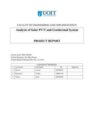
- 1. FACULTY OF ENGINEERING AND APPLIED SCIENCE Analysis of Solar PV/T and Geothermal System PROJECT REPORT Course Code: MECE4430U Course Instructor: Dr. Marc Rosen Project Report Submitted On: Nov. 25, 2015 LAB GROUP MEMBERS # Last Name First Name ID Signature 1 Bower Lowell 100500898 2 Karanwal Tushar 100481186 3 Owais Syed 100506689
- 3. MECE4430U - Analysis of a Solar PV/T and Geothermal System 1 Table of Contents List of Figures................................................................................................................................. 2 List of Tables .................................................................................................................................. 3 1. Abstract.................................................................................................................................... 4 2. Introduction ............................................................................................................................. 5 3. Project Objective/Scope .......................................................................................................... 6 4. System Requirements .............................................................................................................. 7 4.1 Existing System .................................................................................................................... 7 4.2 Ambient Temperature........................................................................................................... 8 4.3 Ventilation Requirements ..................................................................................................... 8 4.4 Electricity and Thermal Generation Targets......................................................................... 9 5. System Overview................................................................................................................... 10 5.1 Diagram............................................................................................................................... 10 5.2 System Operation................................................................................................................ 10 5.3 Components Parameters...................................................................................................... 13 5.4 System Assumptions........................................................................................................... 23 6. System Analysis .................................................................................................................... 24 6.1 Balance Equations............................................................................................................... 24 6.2 Energy and Efficiency......................................................................................................... 26 6.3 Parametric Study................................................................................................................. 27 6.5 Economic Analysis ............................................................................................................. 28 6.6 Environmental Analysis...................................................................................................... 28 7. Conclusion............................................................................................................................. 30 8. Nomenclature......................................................................................................................... 31 9. Appendix ............................................................................................................................... 32 9.1 Figures................................................................................................................................. 32 9.2 Tables.................................................................................................................................. 39 9.3 Sample Calculations............................................................................................................ 41 9.4 EES Code............................................................................................................................ 43 9.5 T-s Diagram ........................................................................................................................ 49 References..................................................................................................................................... 50
- 4. MECE4430U - Analysis of a Solar PV/T and Geothermal System 2 List of Figures Figure 1: Satellite view of 108 High Street (43.921, -78.690) [22]................................................ 7 Figure 2: Proposed system diagram.............................................................................................. 10 Figure 3: ClimateMaster geothermal system [11] ........................................................................ 13 Figure 4: HeatSafe collectors by Enerworks [4]........................................................................... 14 Figure 5: Rinnai R75LSi instantaneous water heater [5].............................................................. 15 Figure 6: SunPower E20-327 solar module [24] .......................................................................... 16 Figure 7: Pika Energy T701 wind turbine..................................................................................... 17 Figure 8: Pika Energy Econotower [14] ....................................................................................... 18 Figure 9: Pika Energy B801 charger controller [14] .................................................................... 19 Figure 10: Pika Energy S2001 MPPT [14]................................................................................... 20 Figure 11: Pika Energy X3001 inverter [14] ................................................................................ 21 Figure 12: Series/parallel battery connection [26]........................................................................ 22 Figure 13: Rolls S-480 battery [25] .............................................................................................. 22 Figure 14: NASA model of CO2 emissions in atmosphere [19] .................................................. 29 Figure 15: Total existing electricity use (August 7, 2013 - October 7, 2014).............................. 32 Figure 16: Average daily existing electricity use (August 7, 2013 - October 7, 2014)................ 32 Figure 17: Average ambient maximum (blue) and minimum (red) temperature for Oshawa...... 33 Figure 18: COP vs. compressor efficiency ................................................................................... 33 Figure 19: Compressor work vs. compressor efficiency .............................................................. 34 Figure 20: Exergy efficiency vs. winter temperature.................................................................... 34 Figure 21: Full-scale proposed system diagram ........................................................................... 35 Figure 22: Enerworks HeatSafe solar thermal collectors ............................................................. 36 Figure 23: Enerworks Energy Stations and hot water storage tank.............................................. 37 Figure 24: Rinnai R75LSi instantaneous water heater ................................................................. 38 Figure 25: T-s diagram for GSHP cycle ....................................................................................... 49
- 5. MECE4430U - Analysis of a Solar PV/T and Geothermal System 3 List of Tables Table 1: GSHP/AHU/HE component parameters......................................................................... 13 Table 2: HeatSafe solar thermal collector component parameters ............................................... 14 Table 3: R75LSi NG instantaneous water heater component parameters .................................... 15 Table 4: E20-327 solar module component parameters ............................................................... 16 Table 5: T701 wind turbine component parameters ..................................................................... 17 Table 6: Econotower component parameters................................................................................ 18 Table 7: B801 charge controller component parameters .............................................................. 19 Table 8: S2001 MPPT component parameters ............................................................................. 20 Table 9: X3001 inverter component parameters........................................................................... 21 Table 10: S-480 battery component parameters ........................................................................... 22 Table 11: Existing system total electricity requirements.............................................................. 39 Table 12: Existing system average electricity requirements and cost .......................................... 39 Table 13: On-peak, mid-peak, and off-peak electricity rates........................................................ 39 Table 14: Natural gas use and thermal energy requirements........................................................ 40 Table 15: Ambient temperature conditions for Oshawa, Ontario [7]........................................... 40
- 6. MECE4430U - Analysis of a Solar PV/T and Geothermal System 4 1. Abstract This report covers a proposal to implement sustainable and alternative energy technologies in order to turn a located at 180 High Street in Bowmanville, Ontario into a positive net energy building. The house in question was already relatively efficient, as it has a solar thermal collector and various high efficiency lights and appliances. A proposed wind turbine, ground source heat pump and solar photovoltaic (PV) modules allowed the system to generate excess energy up to 20%. Greenhouse gas emissions were also mitigated due to the removal of a natural gas furnace for heating. Keywords: Positive energy, renewable energy, solar PV/T, ground source heat pump.
- 7. MECE4430U - Analysis of a Solar PV/T and Geothermal System 5 2. Introduction Energy is needed for humanity to continue the current path of increasing development. It is apparent that we need a solution for the global energy demand, as fossil fuel reserves are on the decline and are becoming more difficult to harvest. Due to technological advancements, there have been many solutions proposed in order to produce clean and sustainable energy. Net-Zero energy buildings are seen as a viable way to mitigate the demand for energy. Net-Zero energy buildings generate enough energy to meet their own demand and can become Net-Positive if they are able to feed power into the grid. This means they would provide more energy than they need, essentially serving as an energy provider. These buildings would implement technologies to harvest ‘clean’ and renewable energy sources, such as solar and wind. They would also provide their heating and cooling needs through sustainable means. Recently, a building in France nicknamed the ‘Hikari’ building, Japanese for ‘light’, was inaugurated. This building produces “slightly more energy (0.2%) than it consumes” [1]. Photovoltaic panels are placed on roofs and various surfaces of the building which produce enough energy to power approximately 160 homes. The system also implements a geothermal system and a cogeneration power plant which uses a biofuel, rapeseed oil [2]. This concept demonstrates the possibility that our energy needs can be met sustainably if the goal of Net-Zero energy is pursued.
- 8. MECE4430U - Analysis of a Solar PV/T and Geothermal System 6 3. Project Objective/Scope A sustainable energy system was to be designed which would result in a positive net energy building. This building would need to provide a 20% net positive by applying at least two sustainable and alternative technologies. Information and data relating to a physical house was used to analyze the current system. Hydro and natural gas bills from the year 2014 were further explored to provide a sound basis of the energy demands of the building currently. Heating and cooling will need to be met in order to meet seasonal demands. The system proposed provides the needed 20% net positive electricity, which could possibly be sold back to the grid as part of Ontario’s Feed-In Tarrif (FIT) program [3]. The following main components are used in the system to meet the demands: - Pika T-701 wind turbine - SunPower E20-327 high efficiency photovoltaic modules - ClimateMaster R-134a based ground source heat pump (GSHP) - Rolls S-480 battery bank By implementing the PV module and the wind turbine, the electricity demands of the house are met. They also are used to charge a bank of batteries which will function as chemical electrical energy storage when the intermittent renewable energy sources are unavailable. The thermal energy needs of the home are met by implementing a ground source heat pump (GSHP), essentially an R-134 based vapor compression cycle. This system employs the earth as a source of heat in the winter and essentially a sink for heat in the summer. It provides a reliable source of heating and cooling while still maintaining a high coefficient of performance as compared to the more commonly used electric heating and cooling methods.
- 9. MECE4430U - Analysis of a Solar PV/T and Geothermal System 7 4. System Requirements 4.1 Existing System The existing system is located at 108 High Street in Bowmanville, Ontario at the approximate coordinates of 43.921, -78.690 (see Figure 1). Space heating for the residence is currently provided by a Frigidaire natural gas furnace and space cooling is provided by a Lennox central air conditioning system that circulates R-410A. Hot water is generated with two HeatSafe flat plate solar thermal collectors (see Figure 22) manufactured by Enerworks [4] which use glycol as a cycle fluid. The existing solar thermal collectors are tied into a hot water storage tank with an Enerworks Energy Station module (see Figure 23). A Rinnai R75LSi natural gas instantaneous water heater (see Figure 24) is installed as a backup source of hot water and used primarily in winter [5]. In order to determine the system requirements data was collected from utility bills provided by Veridian Connections and Enbridge Gas. The electricity requirements were tabulated based on data from August 7, 2013 to August 7, 2014 with data points for every two months. The maximum total electricity use of 1830 kWh was found in the billing period of August 7, 2013 to October 7, 2013. Data provided is tabulated in Section 9.2 Tables and includes total electricity use per billing Figure 1: Satellite view of 108 High Street (43.921, -78.690) [22]
- 10. MECE4430U - Analysis of a Solar PV/T and Geothermal System 8 period (see Table 11), average daily on-peak/mid-peak/off-peak use and total charges per billing period (see Table 12), and electricity rates for on-peak/mid-peak/off-peak use (see Table 13). Existing space heating requirements were calculated using gas consumption values provide by Enbridge Gas. These monthly data points were from August 2013 to July 2014 and were used to calculate the monthly energy input into the system (see Section 9.3 Sample Calculations). For these calculations the density of natural gas (CnH3.8nN0.1n (g)) and lower heating value were assumed to be 0.79 kg/m3 and 50.0 MJ/kg respectively and found from published values [6]. The efficiency of the furnace was assumed to be 90%. In this way thermal energy input to the system was estimated for each month (see Table 14) and a maximum energy input and space heating rate were found to be 4.424 kW and 3.982 kW respectively. This maximum energy requirement occurred during January 2014. This value is an over-estimate since the natural gas use of the Rinnai instantaneous water heater is not taken into account and is used in the winter when the solar thermal array is not sufficient. The home’s electricity and thermal use over time can be analyzed by creating graphs of the tabulated data. As can be seen from Figure 15 the total monthly electricity use was generally highest in the summer and lower in the winter. This is most likely due to the use of the central air conditioning system during summer months which requires more power for the compressor. The average daily electricity use (see Figure 16) follows the same general trend with higher use in the summer compared with the winter. There is an anomalous increase in energy use from October 2013 to December 2013 but the cause could not be determined. 4.2 Ambient Temperature Ambient temperature conditions for the residence were required for the exergy analysis portion of this report. These values were obtained from data provided by the Government of Canada for the Oshawa weather station for the period of August 2013 to July 2014 [7]. This weather station is located at the coordinates (43°55’22”, 78°53’00”) and an elevation of 139.9 m (Climate ID 6155875, WMO ID 71697, TC ID YOO). Using this dataset, the mean temperature, average maximum temperature, and average minimum temperature were found (see Table 15) and a graph of average maximum/minimum temperature for the period were created (see Figure 17). For this system, the year was divided into a summer season from May to October and a winter season from November to April. The maximum average summer temperature of 24.9 °C occurred in August 2013 and the minimum average winter temperature of -14.7 °C occurred in February 2014. 4.3 Ventilation Requirements One of the factors influencing system design was the required ventilation requirements for the building air. The latest residential ventilation standard is ASHRAE 62.2 (2013) released by the
- 11. MECE4430U - Analysis of a Solar PV/T and Geothermal System 9 American Society of Heating, Refrigerating, and Air-Conditioning Engineers (AHSRAE). This standard requires that a ventilation rate of 7.5 cfm per occupant and 3 cfm per 100 ft2 of living space be provided by the heating, ventilation and air-conditioning (HVAC) system for the home [8]. The residence is approximately 1100 ft2 and has three occupants. The density of air for the home (𝜌 𝑎,ℎ𝑜𝑚𝑒) was found using Engineering Equation Solver (EES) for a temperature of 25 °C and a pressure of 101 kPa. The required ventilation for the home was calculated to be approximately 1.850 kg/s (3322.5 cfm) and used to estimate the power requirements for the fan circulating the home air. Some observers have criticized the new ASHRAE standard for requiring an excessive air flow rate; the older 2003 AHSRAE 62.2 standard only required 1 cfm per 100 ft2 living space and some building scientists argued that even this rate was too high [8]. Applying the old formula results in a ventilation requirement that is approximately a third of the required value at 0.625 kg/s. The more stringent requirement of 1.850 kg/s will be used to guide the estimation of power requirements for the air circulation fan in the system. 4.4 Electricity and Thermal Generation Targets Electricity and thermal generation targets can now be determined as the existing system requirements and external parameters have been identified. The winter space heating thermal requirement will be found using the maximum space heating requirement (𝑄̇ℎ𝑒𝑎𝑡𝑖𝑛𝑔) of 3.982 kW from January 2014. A space cooling requirement (𝑄̇ 𝑐𝑜𝑜𝑙𝑖𝑛𝑔) of 0.1602 kW was estimated from Energy Efficiency tables provided by Natural Resources Canada for a single detached home [9]. These tables were also used to estimate a required energy input for water heating (𝑄̇ 𝑤𝑎𝑡𝑒𝑟) of 0.7843 kW. Targeted electricity production will be found by converting the largest total power use of 1850 kWh (for the two month period of August 2013 to November 2013) into a maximum power requirement of 1.271 kW for the existing system. The total power required by the system can be found by subtracting the estimate powered required for the AC system (𝑃𝐴𝐶 = 0.1602 𝑘𝑊) since the ground source heat pump will supply the required cooling. The estimated power required for the GSHP compressor (𝑃𝑐𝑜𝑚𝑝 = 1.282 𝑘𝑊), total system pumps (𝑃𝑝𝑢𝑚𝑝 = 1.056 𝑘𝑊), and AHU fan (𝑃𝐴𝐻𝑈 = 2.112 𝑘𝑊) can be added to this total to obtain a total power requirement of 5.561 kW. In order to be a 20% net export of energy, the total target power for the system (𝑃𝑡𝑜𝑡) will be increased to 6.674 kW. The amount of power required for the solar PV system (𝑃𝑠𝑜𝑙𝑎𝑟) can be found by subtracting the estimated power to be generated by the wind turbine (𝑃 𝑤𝑖𝑛𝑑 = 0.2806 𝑘𝑊). Therefore the power that the new solar PV system must generate is 6.393 kW.
- 12. MECE4430U - Analysis of a Solar PV/T and Geothermal System 10 5. System Overview 5.1 Diagram A small-scale diagram of the proposed system is included below for ease of reference. A larger full-scale image is included in Section 9.1 Figures. 5.2 System Operation The system is divided into two main components, the thermal sub-system and the electrical sub- system. The electrical system includes the following components: solar PV module, PV maximum power-point tracker (MPPT), charge controller, wind turbine, batteries, and inverter. Electrical connections between the compressor and electrical system have been omitted for clarity. Additionally, the system pumps have not be depicted. The operational details of each component are as follows: Figure 2: Proposed system diagram
- 13. MECE4430U - Analysis of a Solar PV/T and Geothermal System 11 Electrical System Operation: 1. Solar PV system o Converts incoming solar radiation into an electrical current. Comprised of multiple PV modules connected in series. 2. Maximum power point tracker o Optimizes the solar PV system output for efficient battery charging. 3. Junction box and DC disconnect o Connects the power output of the solar PV system and wind turbine. Disconnect allows for system service/maintenance. 4. Charge controller o Allows for either charging of battery bank or supply of power to house loads/grid. Manages battery storage for both solar PV and wind system. 5. Inverter o Converts DC power supplied by the solar/wind system into 240 VAC power at 60 Hz. Additional transformer would be required to step power down to 120 VAC required by most home appliances. The thermal sub-system is further divided into the ground source heat pump that will supply the majority of the home’s heating and cooling requirements and the existing solar thermal array and instantaneous natural gas water heater. The GSHP system includes a compressor, reversing valve, interior and exterior air-handling unit/heat exchanger, expansion valve, and ground loop system. R-134a is used as a cycle fluid for states 1-4 and water is used in the ground loop system which will not be exposed to freezing temperatures. The existing water solar thermal/NG water heater has a cycle fluid of 50% propylene glycol USP/EP and distilled water by volume. This system will not be removed but kept as a supplemental thermal energy source. Ground Source Heat Pump Component (GSHP) Operation: 1. Compressor o Used to compress the saturated vapor coming from the cooling heat exchanger. Adds energy to vapor Adds pressure to vapor 2. Interior AHU/heat exchanger o Depending on the mode the GSHP will either be heating or cooling. Heating: this is where the extra energy that was into the saturated refrigerant vapor is expelled into the environment. This is due to the fact that at the elevated pressure the vapor feels “hot” compared to its surroundings, thus it condenses into ideally a saturated liquid. 3. Expansion valve
- 14. MECE4430U - Analysis of a Solar PV/T and Geothermal System 12 o This is here to increase the entropy of working fluid (R-134a). Stage 1: increases velocity of fluid via nozzle effect Stage 2: decreases velocity and increases pressure This suspends liquid particles analogous to a mist into the cooling heat exchanger 4. Exterior AHU/heat exchanger o Depends on the mode of the GSHP, if heating outside heat exchanger will be cold relative to its environment. At this decreased pressure the natural state of the refrigerant is saturated vapor. The liquid particles in the mist evaporate as they collect heat from their surroundings. Known as evaporative cooling. 5. Ground heat exchanging tubes o The reason these tubes are underground is because at a certain depth the temperature remains constant. This is an example of a semi-infinite solid, and an isothermal boundary layer. When using the ground we have access to a vast amount of energy, we can use this medium as a heat source and heat sink. This depends on the mode the GSHP is set at; heating or cooling. Usually we run water through these series of pipes because of water’s high cp and it is easy to pump. This water is pumped to the outside heat exchanger to serve as a heat sink or heat source for the GSHP. 6. Reversing valve o Reverses the flow of R-134a depending on whether the system is in cooling mode (assumed to be May-October) or heating mode (assumed to be November-April). Backup Solar Thermal System Operation: 1. Solar thermal system o Transfers thermal energy from incoming solar radiation to water/glycol fluid. Comprised of two modules connected in series. 2. Storage tank #1 o Transfers thermal energy from the water/glycol in the solar thermal collector to domestic water for home use. Cold city water is input into water tank as water is used. 3. Storage tank #2 o Additional storage of thermal energy for domestic water. Outputs warm water to interior AHU/HE for additional heating and accepts hot water from the GSHP. Outputs warm water to the instantaneous NG backup water heater as needed. 4. Backup instantaneous water heater o Uses natural gas as a fuel to heat up domestic water in case of system failure or if the demand cannot be met.
- 15. MECE4430U - Analysis of a Solar PV/T and Geothermal System 13 5.3 Components Parameters Ground Source Heat Pump/Air Handling Unit/Heat Exchanger Includes ClimateMaster Tranquility 22 geothermal system with a 2-stage compressor, variable speed water flow/air flow control and a ClimateMaster thermostat. Includes Qt1-230 flow controller and four 1 inch by 500 foot coils of high-density polyethylene (HDPE) geothermal pipe [10] [11]. Table 1: GSHP/AHU/HE component parameters COP (Heating) EER (Cooling) Capacity (ton) 4.1 23.7 2 Voltage Input (V) Dimensions (m) Weight (kg) 208/230 0.569 x 0.660 x 1.18 105 Air Filter Cost (CAD) 1” MERV 8 $8217.00 Figure 3: ClimateMaster geothermal system [11]
- 16. MECE4430U - Analysis of a Solar PV/T and Geothermal System 14 Solar Thermal Collectors Two HeatSafe flat plate solar thermal collectors manufactured by Enerworks. Thermal collectors are copper tubes on aluminum and array have glazed tempered glass covers [4]. Table 2: HeatSafe solar thermal collector component parameters Dimensions (Each) (m) Weight (Each) (kg) Coating Absorptance 1.219 x 2.438 x 0.076 5 94% ± 2 Coating Emittance Cost (CAD) 5% ± 2 $0.00 (existing) Figure 4: HeatSafe collectors by Enerworks [4]
- 17. MECE4430U - Analysis of a Solar PV/T and Geothermal System 15 Instantaneous Water Heater The R75LSi instantaneous water heater uses natural gas as a fuel to provide a continuous flow of hot water for domestic use. Exhaust is direct vent/forced combustion with a variable NG input of 9,900-180,000 Btu/h and electronic ignition system [5]. Table 3: R75LSi NG instantaneous water heater component parameters Dimensions (m) Voltage Input (V) Max./Min. Flow Rate (GPM) 0.355 x 0.244 x 0.0229 120 @ 60 Hz (AC) 7.5/0.26 Temperature Range (°C) Thermal Efficiency (%) Cost (CAD) 36.6 to 48.8 82 $0.00 (existing) Figure 5: Rinnai R75LSi instantaneous water heater [5]
- 18. MECE4430U - Analysis of a Solar PV/T and Geothermal System 16 Solar PV Module The E-Series of solar module from SunPower features mono-crystalline silicon Maxeon solar cell technology with a solid copper foundation. This module was ranked number first in the Photovoltaic Durability Initiative (PVDI) performed by the Fraunhofer Institute for Solar Energy Systems (ISE) [12]. Pricing could not be found for this module so the cost was estimated at $3 CAD/W for a total of 20 panels [13]. Table 4: E20-327 solar module component parameters Dimensions (m) Nominal Power (W) Average Module Efficiency (%) 1.559 x 1.046 x 0.046 327 20.4 Rated Voltage (V) Rated Current (A) Open-Circuit Voltage (V) 54.7 5.98 64.9 Short-Circuit Current (A) Cost (CAD) 6.46 $19178 Figure 6: SunPower E20-327 solar module [24]
- 19. MECE4430U - Analysis of a Solar PV/T and Geothermal System 17 Wind Turbine The T701 wind turbine from Pika Energy is a three-blade horizontal wind turbine (HAWT) that features an upwind rotor and free yaw. The blades are glass-reinforced polymer and the alternator is brushless permanent magnet. The system also features a Wi-Fi monitoring system and has been certified by the Small Wind Certification Council (SWCC) [14]. The cost includes the price of a B801 charge controller [15]. Table 5: T701 wind turbine component parameters Rotor Diameter (m) Swept Area (m2 ) Tower Top Weight (kg) 3.0 7.1 42 Peak Output (kW) Rated Output (kW) Monthly Output (kW) 1.7 @ 13.5 m/s 1.5 @ 11 m/s 202 kWh @ 5 m/s Cut In Wind Speed (m/s) Survival Wind Speed (m/s) Cost (CAD) 3.3 66 $5995.00 Figure 7: Pika Energy T701 wind turbine
- 20. MECE4430U - Analysis of a Solar PV/T and Geothermal System 18 Wind Tower The Econotower from Pika Energy uses a gin-pole raising system to install the turbine at a height of either 42’ or 60’ [14]. The following components are also required in order setup the wind tower and can be sourced from an online distributor [16]: Qty 4 - 10.5’ Schedule 40 2.5” Male Thread, Qty 2 - 8’ Copper-Clad Steel Ground Rod, Qty 4 - 5/8”-11 Thread 9” Adjustment Steel Jaw-and-Jaw Turnbuckle with Cotter Pins, Qty 3 - Galvanized Schedule 40 2.5” NPT Pipe Coupler. The following screw anchors are used to secure the system guy wires and can be purchased from American Earth Anchors [17]: Qty 10 - PE46GUY 46” (1.2 m) Penetrator Screw Anchor. These costs are added to the base cost of $999.00 for the Econotower. Table 6: Econotower component parameters Height (m) Tube Specification Total Cost (CAD) 12.8 Sched. 40 2.5” diameter $3040.90 Figure 8: Pika Energy Econotower [14]
- 21. MECE4430U - Analysis of a Solar PV/T and Geothermal System 19 Charge Controller The B801 charge controller from Pika Energy is designed to work with hybrid wind/solar PV systems and can be used with any 24-48 V DC energy system [14]. Table 7: B801 charge controller component parameters Battery Voltage (V) Max. Battery Current (A) Efficiency (%) 24 to 48 ± 80 95 Standby/Sleep Power (W) Temperature Range (°C) Cost (CAD) 7/3 -20 to 50 $0.00 (Included with T701) Figure 9: Pika Energy B801 charger controller [14]
- 22. MECE4430U - Analysis of a Solar PV/T and Geothermal System 20 Maximum Power Point Tracker The S2001 PV Link manufactured by Pika Energy allows for the optimization of a solar PV module and uses natural convection cooling for quiet operation [14]. Table 8: S2001 MPPT component parameters Dimensions (m) Weight (kg) Max. Temperature (°C) 0.235 x 0.102 x 0.210 4.5 60 MPPT Voltage (V) Min. Input Voltage (V) Max. Input Voltage (V) 100-320 DC 100 320 Standby Power (W) Efficiency (%) Cost (CAD) 1 98.9 $995.00 Figure 10: Pika Energy S2001 MPPT [14]
- 23. MECE4430U - Analysis of a Solar PV/T and Geothermal System 21 Inverter The X3001 is a grid-tie inverter which will accept power from any combination of wind/power sources [14]. A cost for this inverter could not be sourced for this report and will not be included in the economic analysis. Table 9: X3001 inverter component parameters Dimensions (m) Weight (kg) Output Voltage (V) 0.381 x 0.381 x 0.152 11.7 240 @ 60 Hz (AC) Max. Current (A) Peak Efficiency (%) Max. Temperature (°C) 13 (AC) 96.3 60 Figure 11: Pika Energy X3001 inverter [14]
- 24. MECE4430U - Analysis of a Solar PV/T and Geothermal System 22 Battery Eight S-480 flooded deep cycle battery from Rolls will be hooked up in a series/parallel configuration for a total system voltage of 24 V and total amperage of 1500 Ah (see Figure 12). Table 10: S-480 battery component parameters Dimensions (m) Weight (kg) Capacity (Each) (Ah) 0.318 x 0.181 x 0.425 37 375 Voltage (V) Hour Rate (hr) Total Cost (CAD) 6 20 $3280 Figure 12: Series/parallel battery connection [26] Figure 13: Rolls S-480 battery [25]
- 25. MECE4430U - Analysis of a Solar PV/T and Geothermal System 23 5.4 System Assumptions 1. Constant room temperature set to 20 °C 2. Constant ground temperature set to 15 °C 3. No head loss in tubing due to major and minor losses 4. Heat exchanger efficiency is 100% 5. Temperatures used for exergy analysis are peak temperature monthly averages. The average temperature of the hottest and coldest month. 6. Dead state temperature is assumed to be 5 °C at 1 atmosphere. 7. House is insulated such that there is no heat loss through walls. Only heating and cooling demands are met. 8. No leakages in the system 9. Nozzle efficiency is assumed to be 100% 10. The system is designed such that it exceed the peak demand by approximately 25%. 11. Steady flow system. 12. Assume 100% efficiencies for electrical components and ignore resistive losses.
- 26. MECE4430U - Analysis of a Solar PV/T and Geothermal System 24 6. System Analysis 6.1 Balance Equations The following equations refer to the proposed system diagram (see Figure 21). Compressor (neglecting reversing valve) Mass Balance Equation: 𝑚̇ 1 = 𝑚̇ 2 Energy Balance Equation: 𝑚̇ 1ℎ1 = 𝑚̇ 2ℎ2 Entropy Balance Equation: 𝑚̇ 1 𝑠1 + 𝑆̇ 𝑔𝑒𝑛 = 𝑚̇ 2 𝑠2 Exergy Balance Equation: 𝑚̇ 1 𝜓1 = 𝑚̇ 2 𝜓2 + 𝐸𝑥̇ 𝑑 Expansion Valve Mass Balance Equation: 𝑚̇ 3 = 𝑚̇ 4 Energy Balance Equation: 𝑚̇ 3ℎ3 = 𝑚̇ 4ℎ4 Entropy Balance Equation: 𝑚̇ 3 𝑠3 + 𝑆̇ 𝑔𝑒𝑛 = 𝑚̇ 4 𝑠4 Exergy Balance Equation: 𝑚̇ 3 𝜓3 = 𝑚̇ 4 𝜓4 + 𝐸𝑥̇ 𝑑 Ground Loop System (when heating, heat is an input) Mass Balance Equation: 𝑚̇ 5 = 𝑚̇ 6 Energy Balance Equation: 𝑚̇ 5ℎ5 + 𝑄̇ℎ𝑒𝑎𝑡𝑖𝑛𝑔 = 𝑚̇ 6ℎ6 Entropy Balance Equation: 𝑚̇ 5 𝑠5 + 𝑆̇ 𝑔𝑒𝑛 + 𝑄̇ℎ𝑒𝑎𝑡𝑖𝑛𝑔 𝑇ℎ𝑒𝑎𝑡𝑖𝑛𝑔 = 𝑚̇ 5 𝑠5 Exergy Balance Equation: 𝑚̇ 3 𝜓3 + 𝐸𝑥̇ 𝑄ℎ𝑒𝑎𝑡𝑖𝑛𝑔 = 𝑚̇ 4 𝜓4 + 𝐸𝑥̇ 𝑑 Ground Loop System (when cooling, heat is an output) Mass Balance Equation: 𝑚̇ 5 = 𝑚̇ 7 Energy Balance Equation: 𝑚̇ 5ℎ5 = 𝑚̇ 7ℎ7 + 𝑄̇ 𝑐𝑜𝑜𝑙𝑖𝑛𝑔 Entropy Balance Equation: 𝑚̇ 5 𝑠5 + 𝑆̇ 𝑔𝑒𝑛 = 𝑚̇ 7 𝑠7 + 𝑄̇ 𝑐𝑜𝑜𝑙𝑖𝑛𝑔 𝑇 𝑐𝑜𝑜𝑙𝑖𝑛𝑔 Exergy Balance Equation: 𝑚̇ 5 𝜓5 = 𝑚̇ 7 𝜓7 + 𝐸𝑥̇ 𝑑 + 𝐸𝑥̇ 𝑄 𝑐𝑜𝑜𝑙𝑖𝑛𝑔
- 27. MECE4430U - Analysis of a Solar PV/T and Geothermal System 25 AHU/HE-interior (when heating) Mass Balance Equation: 𝑚̇ 2 + 𝑚̇ 10 + 𝑚̇ 17 = 𝑚̇ 3 + 𝑚̇ 8𝑎 + 𝑚̇ 18 Energy Balance Equation: 𝑚̇ 2ℎ2 + 𝑚̇ 10ℎ10 + 𝑚̇ 17ℎ17 + 𝑄̇ℎ𝑒𝑎𝑡𝑖𝑛𝑔 = 𝑚̇ 3ℎ3 + 𝑚̇ 8𝑎ℎ8𝑎 + 𝑚̇ 18ℎ18 Entropy Balance Equation: 𝑚̇ 2 𝑠2 + 𝑚̇ 10 𝑠10 + 𝑚̇ 17 𝑠17 + 𝑆̇ 𝑔𝑒𝑛 + 𝑄̇ℎ𝑒𝑎𝑡𝑖𝑛𝑔 𝑇ℎ𝑒𝑎𝑡𝑖𝑛𝑔 = 𝑚̇ 3 𝑠3 + 𝑚̇ 8𝑎 𝑠8𝑎 + 𝑚̇ 18 𝑠18 Exergy Balance Equation: 𝑚̇ 2 𝜓2 + 𝑚̇ 10 𝜓10 + 𝑚̇ 17 𝜓17 + 𝐸𝑥̇ 𝑄ℎ𝑒𝑎𝑡𝑖𝑛𝑔 = 𝑚̇ 3 𝜓3 + 𝑚̇ 8𝑎 𝜓8𝑎 + 𝑚̇ 18 𝜓18 + 𝐸𝑥̇ 𝑑 HE-exterior (when cooling) Mass Balance Equation: 𝑚̇ 4 + 𝑚̇ 5 + 𝑚̇ 9 = 𝑚̇ 1 + 𝑚̇ 7 + 𝑚̇ 8𝑏 Energy Balance Equation: 𝑚̇ 4ℎ4 + 𝑚̇ 5ℎ5 + 𝑚̇ 9ℎ9 = 𝑚̇ 1ℎ1 + 𝑚̇ 7ℎ7 + 𝑚̇ 8𝑏ℎ8𝑏 𝑄̇ 𝑐𝑜𝑜𝑙𝑖𝑛𝑔 Entropy Balance Equation: 𝑚̇ 4 𝑠4 + 𝑚̇ 5 𝑠5 + 𝑚̇ 9 𝑠9 + 𝑆̇ 𝑔𝑒𝑛 = 𝑚̇ 1 𝑠1 + 𝑚̇ 7 𝑠7 + 𝑚̇ 8𝑏 𝑠8𝑏 + 𝑄̇ 𝑐𝑜𝑜𝑙𝑖𝑛𝑔 𝑇𝑐𝑜𝑜𝑙𝑖𝑛𝑔 Exergy Balance Equation: 𝑚̇ 4 𝜓4 + 𝑚̇ 5 𝜓5 + 𝑚̇ 9 𝜓9 = 𝑚̇ 1 𝜓1 + 𝑚̇ 7 𝜓7 + 𝑚̇ 8𝑏 𝜓8𝑏 + 𝐸𝑥̇ 𝑑 + 𝐸𝑥̇ 𝑄 𝑐𝑜𝑜𝑙𝑖𝑛𝑔 Storage Tank #1 Mass Balance Equation: 𝑚̇ 14 + 𝑚̇ 15 = 𝑚̇ 13 + 𝑚̇ 16 Energy Balance Equation: 𝑚̇ 14ℎ14 + 𝑚̇ 15ℎ15 = 𝑚̇ 13ℎ13 + 𝑚̇ 16ℎ16 Entropy Balance Equation: 𝑚̇ 14 𝑠14 + 𝑚̇ 15 𝑠15 + 𝑆̇ 𝑔𝑒𝑛 = 𝑚̇ 13 𝑠13 + 𝑚̇ 16 𝑠16 Exergy Balance Equation: 𝑚̇ 14 𝜓14 + 𝑚̇ 15 𝜓15 = 𝑚̇ 13 𝜓13 + 𝑚̇ 16 𝜓16 + 𝐸𝑥̇ 𝑑 Storage Tank #2 Mass Balance Equation: 𝑚̇ 12 + 𝑚̇ 16 + 𝑚̇ 18 = 𝑚̇ 11 + 𝑚̇ 17 + 𝑚̇ 19 Energy Balance Equation: 𝑚̇ 12ℎ12 + 𝑚̇ 16ℎ16 + 𝑚̇ 18ℎ18 = 𝑚̇ 11ℎ11 + 𝑚̇ 17ℎ17 + 𝑚̇ 19ℎ19 Entropy Balance Equation: 𝑚̇ 12 𝑠12 + 𝑚̇ 16 𝑠16 + 𝑚̇ 18 𝑠18 + 𝑆̇ 𝑔𝑒𝑛 = 𝑚̇ 11 𝑠11 + 𝑚̇ 17 𝑠17 + 𝑚̇ 19 𝑠19 Exergy Balance Equation: 𝑚̇ 12 𝜓12 + 𝑚̇ 16 𝜓16 + 𝑚̇ 18 𝜓18 = 𝑚̇ 11 𝜓11 + 𝑚̇ 17 𝜓17 + +𝑚̇ 19 𝜓19 + 𝐸𝑥̇ 𝑑
- 28. MECE4430U - Analysis of a Solar PV/T and Geothermal System 26 Solar-Thermal Module Mass Balance Equation: 𝑚̇ 13 = 𝑚̇ 14 Energy Balance Equation: 𝑚̇ 13ℎ13 + 𝑄̇ 𝑠𝑜𝑙𝑎𝑟 = 𝑚̇ 14ℎ14 Entropy Balance Equation: 𝑚̇ 13 𝑠13 + 𝑆̇ 𝑔𝑒𝑛 + 𝑄̇ 𝑆𝑜𝑙𝑎𝑟 𝑇 𝑆𝑜𝑙𝑎𝑟 = 𝑚̇ 14 𝑠14 Exergy Balance Equation: 𝑚̇ 13 𝜓13 + 𝐸𝑥̇ 𝑄 𝑆𝑜𝑙𝑎𝑟 = 𝑚̇ 14 𝜓14 + 𝐸𝑥̇ 𝑑 Backup Instantaneous Water Heater Mass Balance Equation: 𝑚̇ 11 = 𝑚̇ 12 Energy Balance Equation: 𝑚̇ 11ℎ11 + 𝑄̇ 𝑁𝑎𝑡𝑢𝑟𝑎𝑙 𝐺𝑎𝑠 = 𝑚̇ 12ℎ12 Entropy Balance Equation: 𝑚̇ 11 𝑠11 + 𝑆̇ 𝑔𝑒𝑛 + 𝑄̇ 𝑁𝑎𝑡𝑢𝑟𝑎𝑙 𝐺𝑎𝑠 𝑇 𝑁𝑎𝑡𝑢𝑟𝑎𝑙 𝐺𝑎𝑠 = 𝑚̇ 12 𝑠12 Exergy Balance Equation: 𝑚̇ 11 𝜓11 + 𝐸𝑥̇ 𝑄 𝑁𝑎𝑡𝑢𝑟𝑎𝑙 𝐺𝑎𝑠 = 𝑚̇ 12 𝜓12 + 𝐸𝑥̇ 𝑑 6.2 Energy and Efficiency The first law of thermodynamics states that energy cannot be created or destroyed, it merely changes form. Energy efficiency is given by the division of desired output by required input. When it comes to refrigeration systems we need to change this concept and introduce another name for this parameter; coefficient of performance. This is because when doing the calculations for efficiency for such systems, we get a value that is greater than 1 which is normally not a sensible result for real systems. This is not the only problem that is presented by these systems but, we know from heat transfer that energy moves only from a hot body to a cold body, in a heat pump system the opposite is happening. The one thing that that explains both of these presented problems is that these types of systems utilize phase change of its working fluid to attain their desired outputs. Referring to system overview (see Section 5.2 System Operation), we can refresh our knowledge on what is happening to the working fluid after each component in the ground source heat pump cycle. The highest efficiency thermal cycle is known as the Carnot cycle. This is a cycle where every single process is reversible and it is calculated using only the high and low temperatures of the system. This serves as a comparison tool to see how close a modeled system is to being the best it can physically be. The COPCarnot,HP and COPCarnotR for our system design are 5.08 and 4.08 respectively. When we compare the actual COP values to the Carnot COP we can see that values of 81.41% and 77.87% of the Carnot COP for COPHP and COPR are being reached respectively. This shows that our system is incredibly efficient, but we must also take into consideration the
- 29. MECE4430U - Analysis of a Solar PV/T and Geothermal System 27 assumptions made in our calculations and parameters. In reality these numbers will be significantly lower due to losses and irreversibilities that remain unaccounted for. Expanding on irreversibilities, the second law of thermodynamics states that in any cyclic process, the entropy will either increase or remain the same. Energy is divided into two categories, the first one being anergy which is a portion of energy that is wasted and cannot be converted to work. The remaining portion of energy is called exergy, this is easily defined as useful work. Exergy analysis is an extremely powerful tool that can serve as a comparison value like the Carnot value when discussing efficiencies. For example, we know that energetically the efficiency of an electrical space heater is 99%-100%, i.e. the amount of energy supplied is the amount of heat energy received. But when using exergy analysis we see that “exergy analysis recongnizes this difference in energy qualities and indicates the exergy of the heat deliverd to the room to be about 5% of the exergy entering the heater” [18]. In our system we can see that our overall exergy efficiency is 65.79% this is an acceptable efficiency and it shows us that we are able to convert 65.79% of all useful work supplied to our system to the desired output. This efficiency depends on the ambient temperatures of the environment, which will be discussed in the following parametric study. 6.3 Parametric Study Referring to Figure 18 and Figure 19 we can see that the coefficient of performance increases as the efficiency of the compressor is increased, while decreasing the work required to compress the vapor to its desired pressure. By increasing the compressor efficiency we decrease the irreversible losses during this process. Also by increasing the efficiency of the compressor work we also increase the exergy efficiency, this is understood when looking at the exergy efficiency formula: 𝜂𝐼𝐼 = 𝐸𝑥𝑒𝑟𝑔𝑦 𝑅𝑒𝑐𝑜𝑣𝑒𝑟𝑒𝑑 𝐸𝑥𝑒𝑟𝑔𝑦 𝑠𝑢𝑝𝑝𝑙𝑖𝑒𝑑 We can see that as we decrease the exergy supplied by increasing the compressor efficiency it will inherently increase the second law efficiency. When dealing with exergy, temperature is a crucial parameter to consider. The following figure represents the behavior of exergy efficiency as we decrease the winter ambient temperature. This analysis was conducted while the GSHP was in heating mode. Another way of calculating the second law efficiency is through exergy destruction. Exergy destruction is a value that represents the amount of exergy that is wasted during a process. Exergy destruction can be calculated using two main methods: ExD = T0 Ṡgen where Ṡgen is the increase of entropy from a process. The second
- 30. MECE4430U - Analysis of a Solar PV/T and Geothermal System 28 method utilizes the difference of exergy flows, where the equation for a single flow is given by ψi = (hi – h0) – T0(si –s0). For the proposed system an increase of exergy efficiency was observed as the ambient temperature was decreased (see Figure 20). This is due to the fact that the ground is being used as a heat source, since our heat source temperature remains constant and is not affected by the ambient temperature we are able to effectively heat a space without additional work. By decreasing the ambient temperature in the winter the individual exergy flow values are affected, in this case the exergy flow of the inlet winter air is increased. By doing this the exergy destroyed in the condenser for heating mode is decreased. Relatively speaking, the useful work provided at a colder temperature is more effectively used than compared to a higher temperature. 6.5 Economic Analysis Component costs have been collected for most of the proposed products that are to be installed in this system (see Section 5.3 Components Parameters). Using these values a total purchase cost of $40,706 (CAD) is estimated. It should be noted that this value estimates the cost of the SunPower solar modules and does not include the cost of a transformer or the X3001 inverter. Additionally, the installation and maintenance cost for this system has not been estimated and would add significantly to the total cost. The payback period for the system can be estimated by assuming that it would be eligible for the Ontario Feed-In Tarrif (FIT) program and receive the electricity price of 29.4 (¢/kWh) [3] applied to the solar PV subsystem. If it is assumed that the entire excess 20% of electricity is sold back to the grid at this rate there will be approximately 1.334 kW of power or 32.03 kWh/day available. At this rate it will take approximately 4322 days (11.84 years) to recover the cost of the components alone. This assumes that no government grants have been used to install the system. 6.6 Environmental Analysis Greenhouse gas emissions is one of the major issues related to the energy sector globally. It is a “key driver of global warming” [19]. The system proposed eliminates the use of natural gas, which was used to heat water and air for the house in question. A simulation depicting the CO2 emissions in the atmosphere shows that North America is essentially covered by a large concentrated cloud of CO2 (see Figure 14) The total amount of natural gas used in the house, prior to any improvements, was found to be approximately 1100 m3 (annually). This results in approximately 2100 tonnes of CO2 expelled annually [20].
- 31. MECE4430U - Analysis of a Solar PV/T and Geothermal System 29 The proposed system implements a solar thermal collector which uses a propylene-glycol-water solution as working fluid. There have been many studies done to find the hazards of this solution pertaining to ecological and human impacts. Propylene-glycol is considered to be a relatively safe chemical. Due to it breaking down quickly in the body, is it difficult to detect. The FDA classifies the chemical “generally safe”, as it is used in flavorings, cosmetics and even edibles. [21] Figure 14: NASA model of CO2 emissions in atmosphere [19]
- 32. MECE4430U - Analysis of a Solar PV/T and Geothermal System 30 7. Conclusion The proposed system for a net positive energy building was designed using a wind turbine, solar PV/T modules and a ground source heat pump. The system produced an excess of 20% of its energy demands, while also providing its own thermal requirements needed for heating and cooling. The total electrical load (plus 20%) for the house was found to be 6.674 kW with 0.2806 kW being supplied by the wind turbine and 6.393 kW being generated by the PV array. The thermal needs of the house for cooling and heating were estimated at 3.982 kW during the winter and 0.1602 kW during the summer with an additional 0.7843 kW for domestic hot water heating. These needs were met by implementing a vapor compression cycle and a ground source heat pump, using R- 134a and water as their working fluid respectively. The home’s existing flat-plate solar thermal array and instantaneous NG water heater were kept as a supplementary/backup source of hot water. Due to providing energy for space heating and hot water, it was found that approximately 2100 tonnes of CO2 was saved from being released from the environment. This value assumes that no natural gas is burned in the NG water heat. The excess energy provided by the house could essentially be sold to the grid, which would annually generate approximately $3437.43 per year at a reimbursement rate of 29.4 (¢/kWh). The resulting payback period is approximately 12 years (not including installation costs). Possible issues with the analysis include overestimates for the power consumption of the system by the pumps, fans, and compressor. Additionally 20 solar modules are required to generate the required electricity however there is not enough south-facing area on the roof to accommodate an array of this size. It is possible to install panels on the ground however there are trees on the lot (see Figure 1) that would have to be removed. Another simplification is that the rated wind turbine and solar PV output have been used to size the system. A more thorough analysis would have considered regional and seasonal variations to estimate the power output of these renewable systems.
- 33. MECE4430U - Analysis of a Solar PV/T and Geothermal System 31 8. Nomenclature General AC = Alternating Current AHU = Air-Handling Unit ASHRAE = American Society of Heating, Refrigerating, and Air-Conditioning Engineers COP = Coefficient of Performance DC = Direct Current EES = Engineering Equation Solver FIT = Feed-In Tarrif Program GPM = Gallons Per Minute GSHP = Ground Source Heat Pump HDPE = High-Density Polyethylene HE = Heat Exchanger ISE = Fraunhofer Institute for Solar Energy Systems MPPT = Maximum Powerpoint Tracker NG = Natural Gas PV = Photovoltaic SWCC = Small Wind Certification Council System Parameters 𝐸𝐵𝐸 - Energy Balance Equation 𝐸𝑛𝐵𝐸 - Entropy Balance Equation 𝐸𝑥𝐵𝑒 - Exergy Balance Equation 𝐸𝑥̇ 𝑑 - Exergy Destruction Rate ℎ - Specific Enthalpy 𝑚̇ - Mass Flow Rate 𝑀𝐵𝐸 - Mass Balance Equation 𝑃 = Power 𝑄̇ - Heat Rate 𝑠 - Specific Enthalpy 𝑆̇ 𝑔𝑒𝑛 - Entropy Generation Rate 𝑇 - Temperature Greek Letters 𝜂 - Efficiency 𝜓 - Flow Exergy
- 34. MECE4430U - Analysis of a Solar PV/T and Geothermal System 32 9. Appendix 9.1 Figures 1550.00 1600.00 1650.00 1700.00 1750.00 1800.00 1850.00 06-25-13 08-14-13 10-03-13 11-22-13 01-11-14 03-02-14 04-21-14 06-10-14 07-30-14 TotalElectricityUse(kWh) Date 26.00 26.50 27.00 27.50 28.00 28.50 29.00 29.50 30.00 30.50 06-25-13 08-14-13 10-03-13 11-22-13 01-11-14 03-02-14 04-21-14 06-10-14 07-30-14 AverageDailyUse(kWh) Date Figure 15: Total existing electricity use (August 7, 2013 - October 7, 2014) Figure 16: Average daily existing electricity use (August 7, 2013 - October 7, 2014)
- 35. MECE4430U - Analysis of a Solar PV/T and Geothermal System 33 -20 -15 -10 -5 0 5 10 15 20 25 30 06-25-13 08-14-13 10-03-13 11-22-13 01-11-14 03-02-14 04-21-14 06-10-14 07-30-14 Temperature(°C) Date Figure 17: Average ambient maximum (blue) and minimum (red) temperature for Oshawa 4.84 5.08 5.32 5.56 3.84 4.08 4.32 4.56 3 3.5 4 4.5 5 5.5 6 0.78 0.8 0.82 0.84 0.86 0.88 0.9 0.92 0.94 0.96 CoefficientofPerformance Efficiency COP COPr Figure 18: COP vs. compressor efficiency
- 36. MECE4430U - Analysis of a Solar PV/T and Geothermal System 34 1.362 1.282 1.211 1.147 1.1 1.15 1.2 1.25 1.3 1.35 1.4 0.78 0.8 0.82 0.84 0.86 0.88 0.9 0.92 0.94 0.96 Work(kW) Efficiency Compressor work vs. Compressor Efficency Figure 19: Compressor work vs. compressor efficiency 65.5 66 66.5 67 67.5 68 68.5 69 69.5 70 70.5 -40 -35 -30 -25 -20 -15 -10 ExergyEfficiency(%[) Temperature (°C) Figure 20: Exergy efficiency vs. winter temperature
- 37. MECE4430U - Analysis of a Solar PV/T and Geothermal System 35 Figure 21: Full-scale proposed system diagram
- 38. MECE4430U - Analysis of a Solar PV/T and Geothermal System 36 Figure 22: Enerworks HeatSafe solar thermal collectors
- 39. MECE4430U - Analysis of a Solar PV/T and Geothermal System 37 Figure 23: Enerworks Energy Stations and hot water storage tank
- 40. MECE4430U - Analysis of a Solar PV/T and Geothermal System 38 Figure 24: Rinnai R75LSi instantaneous water heater
- 41. MECE4430U - Analysis of a Solar PV/T and Geothermal System 39 9.2 Tables Table 11: Existing system total electricity requirements Period # Billing Period Start Billing Period End Total Days Total Use (kWh) Total Use (kW) 1 08/07/13 10/07/13 61 1830.00 1.250 2 10/07/13 12/07/13 61 1603.01 1.095 3 12/07/13 02/07/14 62 1749.00 1.175 4 02/07/14 04/07/14 59 1620.99 1.145 5 04/07/14 06/07/14 61 1678.00 1.146 6 06/07/14 08/07/14 61 1774.00 1.212 Table 12: Existing system average electricity requirements and cost Period # Average Daily Use (kWh) Average On- Peak Daily Use (kWh) Average Mid- Peak Daily Use (kWh) Average Off- Peak Daily Use (kWh) Total Charge (CAD) 1 30.00 6 5 19 257.63 2 26.28 5 4 17 240.88 3 28.21 5 5 19 262.99 4 27.47 4 4 19 242.66 5 27.51 5 5 18 262.88 6 29.08 6 5 19 281.88 Table 13: On-peak, mid-peak, and off-peak electricity rates 2013 Summer On-Peak Rate (¢/kWh) 2013 Summer Mid-Peak Rate (¢/kWh) 2013 Summer Off-Peak Rate (¢/kWh) 12.40 10.40 6.70 2013 Winter On-Peak Rate (¢/kWh) 2013 Winter Mid-Peak Rate (¢/kWh) 2013 Winter Off-Peak Rate (¢/kWh) 12.90 10.90 7.20 2014 Summer On-Peak Rate (¢/kWh) 2014 Summer Mid-Peak Rate (¢/kWh) 2014 Summer Off-Peak Rate (¢/kWh) 13.50 11.20 7.50
- 42. MECE4430U - Analysis of a Solar PV/T and Geothermal System 40 Table 14: Natural gas use and thermal energy requirements Date Natural Gas Use (m3 ) Days per Month Energy Input (kW) Space Heating (kW) 08/01/13 10.0 31 0.1475 0.1327 09/01/13 10.0 30 0.1475 0.1327 10/01/13 12.5 31 0.1843 0.1659 11/01/13 100.0 30 1.475 1.327 12/01/13 137.5 31 2.028 1.825 01/01/14 300.0 31 4.424 3.982 02/01/14 225.0 28 3.318 2.986 03/01/14 225.0 31 3.318 2.986 04/01/14 140.0 30 2.065 1.858 05/01/14 70.0 31 1.0323 0.9291 06/01/14 30.0 30 0.4424 0.3982 07/01/14 10.0 31 0.1475 0.1327 Table 15: Ambient temperature conditions for Oshawa, Ontario [7] Date Mean Temperature (°C) Average Max. Temperature (°C) Average Min. Temperature (°C) 08/01/13 19.1 24.9 13.2 09/01/13 14.3 20.1 8.5 10/01/13 9.7 14.8 4.6 11/01/13 0.9 5.5 -3.8 12/01/13 -5.4 -1.5 -9.2 01/01/14 -8.4 -3.8 -13.1 02/01/14 -9.5 -4.2 -14.7 03/01/14 -4.8 0.2 -9.9 04/01/14 5.1 10.5 -0.3 05/01/14 13.4 18.9 7.8 06/01/14 18.1 23.8 12.4 07/01/14 19.0 24.8 13.1
- 43. MECE4430U - Analysis of a Solar PV/T and Geothermal System 41 9.3 Sample Calculations Thermal Energy Input: Convert natural gas use for January 2014 into energy input. 𝑉̇ 𝑁𝐺 = 300 𝑚3 31 𝑑𝑎𝑦𝑠 𝜌 𝑁𝐺 = 0.79 𝑘𝑔 𝑚3 [6] 𝐿𝐻𝑉𝑁𝐺 = 50.0 𝑀𝐽 𝑘𝑔 [6] 𝑄̇ 𝑖𝑛 = 𝜌 𝑁𝐺 𝑉̇ 𝑁𝐺 𝐿𝐻𝑉𝑁𝐺 ∴ 𝑄̇ 𝑖𝑛 = (0.79 𝑘𝑔 𝑚3 ) ( 300 𝑚3 31 𝑑𝑎𝑦𝑠 ) ( 1 𝑑𝑎𝑦 86400 𝑠 ) (50.0 · 103 𝑘𝐽 𝑘𝑔 ) ≈ 4.424 𝑘𝑊 Required Thermal Energy: Calculate the required thermal energy into the system by accounting for the estimated efficiency of the furnace. 𝜂 𝑓𝑢𝑟𝑛𝑎𝑐𝑒 = 0.90 𝑄̇ 𝑟𝑒𝑞 = 𝜂 𝑓𝑢𝑟𝑛𝑎𝑐𝑒 𝑄̇ 𝑖𝑛 = (0.90)(4.424 𝑘𝑊) ≈ 3.982𝑘𝑊 Required Ventilation: Calculate the required ventilation rate for the home. 𝑉̇ 𝑎,𝑜𝑐𝑐𝑢𝑝𝑎𝑛𝑡 = 7.5 𝑐𝑓𝑚 𝑜𝑐𝑐𝑢𝑝𝑎𝑛𝑡 [8] 𝑉̇𝑎,𝑎𝑟𝑒𝑎 = 7.5 𝑐𝑓𝑚 100 𝑓𝑡2 [8] 𝑛 𝑜𝑐𝑐𝑢𝑝𝑎𝑛𝑡 = 3 𝑜𝑐𝑐𝑢𝑝𝑎𝑛𝑡𝑠 𝐴ℎ𝑜𝑚𝑒 = 1100 𝑓𝑡2 𝜌 𝑎,ℎ𝑜𝑚𝑒 = 1.180 𝑘𝑔 𝑚3 [EES] 𝑚̇ 𝑎,ℎ𝑜𝑚𝑒 = 𝜌 𝑎,ℎ𝑜𝑚𝑒(𝑉̇ 𝑎,𝑜𝑐𝑐𝑢𝑝𝑎𝑛𝑡 𝑛 𝑜𝑐𝑐𝑢𝑝𝑎𝑛𝑡 + 𝑉̇𝑎,𝑎𝑟𝑒𝑎 𝐴ℎ𝑜𝑚𝑒) ∴ 𝑚̇ 𝑎,ℎ𝑜𝑚𝑒 = (1.180 𝑘𝑔 𝑚3 ) [( 7.5 𝑐𝑓𝑚 𝑜𝑐𝑐𝑢𝑝𝑎𝑛𝑡 ) (3) + ( 7.5 𝑐𝑓𝑚 100 𝑓𝑡2 ) (1100 𝑓𝑡2)] ( 1 𝑚3 35.3147 𝑓𝑡3 ) ( 1 𝑚𝑖𝑛 60 𝑠 ) ∴ 𝑚̇ 𝑎,ℎ𝑜𝑚𝑒 ≈ 1.850 𝑘𝑔 𝑠
- 44. MECE4430U - Analysis of a Solar PV/T and Geothermal System 42 Power Requirement: Calculate the power requirement for the system. 𝑃2𝑚𝑜𝑛𝑡ℎ = 1830 𝑘𝑊ℎ 61 𝑑𝑎𝑦𝑠 = (1830 𝑘𝑊)(3600 𝑠) 61 𝑑𝑎𝑦𝑠 ( 1 𝑑𝑎𝑦 86400 𝑠 ) ≈ 1.25 𝑘𝑊 Subtract an estimated 0.1602 kW for AC use which will be supplied by the GSHP system. Add in the required 1.282 kW for the compressor, 2.112 kW for the AHU fan, and 1.056 kW for the system pumps. 𝑃𝑡𝑜𝑡 = 1.2(1.25 − 0.1602 − 0.2806 + 1.282 + 2.112 + 1.056)𝑘𝑊 ≈ 6.674 𝑘𝑊 The 0.2806 kW power to be supplied by the wind turbine can be removed to find the estimated power required by the solar PV system. 𝑃𝑠𝑜𝑙𝑎𝑟 = 𝑃𝑡𝑜𝑡 − 𝑃 𝑤𝑖𝑛𝑑 = (6.674 − 0.2806) 𝑘𝑊 ≈ 6.393 𝑘𝑊
- 45. MECE4430U - Analysis of a Solar PV/T and Geothermal System 43 9.4 EES Code "Refrigeration Cycle" p[1]=350 [kPa] p[2]=1300 [kPa] m_dot_refrig= 0.04 [kg/s] eta_pump_Refrig= .85 "Pump efficiency" h[3]=h[4] h2s = enthalpy(R134a, s=s[1],P=P[2]) eta_pump_refrig = (h2s-h[1])/(h[2]-h[1]) "efficiency equation to solve for h[2]" h[1]=enthalpy(R134a,x=x[1] ,P=P[1]) ;x[1]=1.0 s[1]=entropy(R134a,x=x[1],P=P[1]) h[2]=enthalpy(R134a,s=s[2],P=P[2]) h[3]=enthalpy(R134a,x=x[3],P=P[2]) ;x[3]=0 s[3]=entropy(R134a,x=x[3],P=P[2]) s[4]=entropy(R134a,h=h[4],P=P[4]);p[4]=p[1];p[3]=p[2] t[1]=temperature(R134a,h=h[1],P=P[1]) t[2]=temperature(R134a,s=s[2],P=P[2]) t[3]=temperature(R134a,x=x[3],P=P[2]) t[4]=t[1] x[4]=quality(R134a,h=h[4],P=P[4]) "Analysis" Q_dot_evap=m_dot_refrig*(h[1]-h[4]) "heat removed in evaporator" Q_dot_cond=m_dot_refrig*(h[2]-h[3]) "heat exchanged to atmosphere in condenser" W_dot_comp_refrig=m_dot_refrig*(h[2]-h[1]) "compressor power" COP_R=Q_dot_evap/W_dot_comp_refrig "coefficient of performance Refrig" COP_HP=COP_R+1 COP_Carnot_HP = 1/(1-((t[4]+273)/(t[2]+273))) COP_Carnot_R = 1/(((t[2]+273)/(t[4]+273))-1) Percent_COP_R = COP_R/COP_carnot_R " this is the percentage of how close we are to carnot" Percent_COP_HP = COP_HP/COP_carnot_HP " this is the percentage of how close we are to carnot" "Thermal Load" Winter_thermal_load = 3.982 [kW] Summer_thermal_load = 0.1602 [kW] Water_heating_load = 0.7843 [kW] "Fraction of how much the system is used relative to max capacity of the system" Load_Factor_heating = (Winter_thermal_load+water_heating_load)/Q_dot_cond Load_Factor_cooling = Summer_thermal_load/Q_dot_evap "Tons of heating and cooling Calculations" Ton_heating = Winter_thermal_load/3.5168525 Ton_cooling = Summer_thermal_load/3.5168525 "Ground tubes" T_inlet = 15 [C] T_outlet_winter = (Q_dot_cond)/((0.3)*(c_p_water)) +15 T_outlet_summer = 15 - (Q_dot_evap)/((0.3)*(c_p_water)) m_dot_ground_tubes = 0.3 [kg/s] c_p_water = cp(water, T= 15, x=0) P_water= 200 "Inlet water ground"
- 46. MECE4430U - Analysis of a Solar PV/T and Geothermal System 44 h[5] = enthalpy(water, T= T_inlet, P = P_water) s[5] =entropy(water, T= T_inlet, P = P_water) "outlet in winter ground" h[6] = enthalpy(water, T= T_outlet_winter, P = P_water) s[6] = entropy(water, T= T_outlet_winter, P = P_water) "outlet in summer ground" h[7] = enthalpy(water, T= T_outlet_summer, P = P_water) s[7] = entropy(water, T= T_outlet_summer, P = P_water) "Air Space Heating Air vents" T_house = 20 T_winter = -30 T_summer = 24.9 density_air = density(air_ha, T=20, p=101.3) cp_air_cold = cp(air, T=-14.7) cp_air_hot = cp(air, T=24.9) delta_t_cold = T_house - T_winter delta_t_hot = T_summer-T_house m_dot_air_heating = (winter_thermal_load+water_heating_load)/(cp_air_cold *delta_T_cold) "Mass flow of air to meet demands" m_dot_air_cooling = (summer_thermal_load)/(cp_air_cold *delta_T_cold) "Mass flow of air to meet demands" "Pump and Fan work" Water_geo_pump = 1.05639 [kW] Fan_work_air = 2.1122 [kW] "Ambient air/outlet air" h[8] = enthalpy(air_ha, T=20, P=101.3) s[8] = entropy(air_ha, T=20,P=101.3) "inlet air summer" h[9] = enthalpy(air_ha, T = T_summer, P = 101.3) s[9] = entropy(air_ha, T = T_summer, P = 101.3) "inlet air winter" h[10] = enthalpy(air_ha, T = T_winter, P = 101.3) s[10] = entropy(air_ha, T = T_winter, P = 101.3) "Exergy Flow" T_soil = 15+273 T_0_r = 5+273 T_0_w = 5+273 T_0_air = 5+273 s_0_r = entropy(R134a, T=5, P= 101.3) h_0_r = enthalpy(R134a, T=5, P = 101.3) s_0_w = entropy(water, T=5, P= 101.3) h_0_w = enthalpy(water, T=5, P = 101.3) s_0_air = entropy(air_ha, T=5, P= 101.3) h_0_air = enthalpy(air_ha, T=5, P = 101.3) psi_1 = (h[1] - h_0_r) - T_0_r*(s[1]-s_0_r) psi_2 = (h[2] - h_0_r) - T_0_r*(s[2]-s_0_r) psi_3 = (h[3] - h_0_r) - T_0_r*(s[3]-s_0_r) psi_4 = (h[4] - h_0_r) - T_0_r*(s[4]-s_0_r)
- 47. MECE4430U - Analysis of a Solar PV/T and Geothermal System 45 psi_5 = (h[5] - h_0_w) - T_0_w*(s[5]-s_0_w) "Inlet water" psi_6 = (h[6] - h_0_w) - T_0_w*(s[6]-s_0_w) "outlet winter water" psi_7 = (h[7] - h_0_w) - T_0_w*(s[7]-s_0_w) "outlet summer water" psi_8 = (h[8] - h_0_air) - T_0_air*(s[8]-s_0_air) "ambient air" psi_9 = (h[9] - h_0_air) - T_0_air*(s[9]-s_0_air) "summer air " psi_10 = (h[10] - h_0_air) - T_0_air*(s[10]-s_0_air) "winter air" "Exergy Destruction" X_d_comp = m_dot_refrig*(psi_1-psi_2)+W_dot_comp_refrig X_d_cond_heating = m_dot_refrig*(psi_2-psi_3) + m_dot_air_heating*(psi_8-psi_10) X_d_exp = m_dot_refrig*(psi_3-psi_4) X_d_evap_heating = m_dot_refrig*(psi_4-psi_1)+ m_dot_ground_tubes*(psi_6-psi_5) X_d_ground_HE_heat = m_dot_ground_tubes*(psi_6-psi_5)+ (m_dot_ground_tubes*c_p_water*(T_outlet_winter-T_inlet))*(1-(T_0_w/T_soil)) X_d_air_HE_heat = m_dot_air_heating*(psi_8 - psi_10) - (m_dot_air_heating*cp_air_cold*(T_house- T_winter))*(1-(T_0_w/(T_winter+273))) X_d_total = X_d_comp+X_d_cond_heating+X_d_exp+X_d_evap_heating X_supplied_total = W_dot_comp_refrig + water_geo_pump +fan_work_air eta_exergy = (1 - (x_d_total/x_supplied_total)) *100 ===================================================================== Formatted Equations =====================================================================
- 48. MECE4430U - Analysis of a Solar PV/T and Geothermal System 46
- 49. MECE4430U - Analysis of a Solar PV/T and Geothermal System 47
- 50. MECE4430U - Analysis of a Solar PV/T and Geothermal System 48
- 51. MECE4430U - Analysis of a Solar PV/T and Geothermal System 49 9.5 T-s Diagram Figure 25: T-s diagram for GSHP cycle
- 52. MECE4430U - Analysis of a Solar PV/T and Geothermal System 50 References [1] Global Buildings Performance Network, "A success story: the Hikari project," 23 September 2015. [Online]. Available: http://www.gbpn.org/newsroom/news-success- story-hikari-project. [Accessed 24 November 2015]. [2] Next Buildings, "Hikari Building," 2015. [Online]. Available: http://next- buildings.com/index.php/about/hikaribuilding. [Accessed 24 November 2015]. [3] Independent Electricity System Operator, "FIT/microFIT PRICE SCHEDULE (January 1, 2016)," 2015. [Online]. Available: http://fit.powerauthority.on.ca/sites/default/files/FIT%20Price%20Schedule%202016-01- 01.pdf. [Accessed 16 November 2015]. [4] Enerworks Inc., "Solar Heating and Cooling," 2015. [Online]. Available: http://enerworks.com/. [Accessed 2 November 2015]. [5] Rinnai Corporation, "Tankless Water Heaters," 2015. [Online]. Available: http://www.rinnai.ca/tankless-water-heater. [Accessed 4 November 2015]. [6] J. B. Heywood, Internal Combustion Engine Fundamentals, New York: McGraw-Hill, 1988. [7] Government of Canada, "Daily Data Report," 22 September 2015. [Online]. Available: http://climate.weather.gc.ca/climateData/dailydata_e.html?timeframe=2&Prov=ON&Stati onID=48649&dlyRange=2010-06-03|2015-11-21&Year=2015&Month=11&Day=01. [Accessed 12 November 2015]. [8] M. Holladay, "How Much Fresh Air Does Your Home Need?," Green Building Advisor, 28 June 2013. [Online]. Available: http://www.greenbuildingadvisor.com/blogs/dept/musings/how-much-fresh-air-does-your- home-need. [Accessed 15 November 2015]. [9] Natural Resources Canada, "Energy Efficiency Analysis Tables," 1 January 2014. [Online]. Available: http://open.canada.ca/data/en/dataset/a3ef9fb0-f63f-4a7e-b11d- 6743166a4032. [Accessed 22 November 2014]. [10] CMDealernet, "Tranquility® 22 Digital Series (TZ)," 2015. [Online]. Available: http://www.climatemaster.com/geothermal-dealer/geothermal-product-literature/tz/. [Accessed 16 November 2015]. [11] ebay, "2 ton 2 stage Geothermal Climatemaster heat Pump Install Package TZv024," 2015. [Online]. Available: http://www.ebay.com/itm/2-ton-2-stage-Geothermal- Climatemaster-heat-Pump-Install-Package-TZv024-/252179706699. [Accessed 16 November 2015]. [12] Fraunhofer USA, "Photovoltaic Technologies: The PV Module Durability Initiative (PVDI)," 2015. [Online]. Available: http://www.cse.fraunhofer.org/pv-technologies/pv- module-durability-initiative. [Accessed 16 November 2015].
- 53. MECE4430U - Analysis of a Solar PV/T and Geothermal System 51 [13] FreeCleanSolar, "Sunpower 327 Solar Panels," 2015. [Online]. Available: http://www.freecleansolar.com/SunPower-327-Solar-Panels-s/4580.htm. [Accessed 16 November 2015]. [14] Pika Energy Ltd., "Pika Energy," 2015. [Online]. Available: http://www.pika- energy.com/. [Accessed 16 November 2015]. [15] RaySolar, "Pika Energy — 3.7kW Hybrid Wind/Solar System," 2015. [Online]. Available: http://raysolar.ca/product/pika-energy-3-7kw-hybrid-windsolar-system/. [Accessed 16 November 2015]. [16] McMaster Carr, "McMaster Carr," 2015. [Online]. Available: http://www.mcmaster.com/. [Accessed 16 November 2015]. [17] American Earth Anchors, "Penetrator Screw Anchors," 2015. [Online]. Available: https://americanearthanchors.com/products/ground-anchors-penetrators/. [Accessed 16 November 2015]. [18] What-When-How, "Exergy: Analysis (Energy Engineering)," 2015. [Online]. Available: http://what-when-how.com/energy-engineering/exergy-analysis-energy-engineering/. [Accessed 19 November 2015]. [19] National Aeronautics and Space Administration, "NASA Computer Model Provides a New Portrait of Carbon Dioxide," 17 November 2014. [Online]. Available: http://www.nasa.gov/press/goddard/2014/november/nasa-computer-model-provides-a- new-portrait-of-carbon-dioxide/#.VH0ENjHF98E. [Accessed 1 December 2014]. [20] Environment Canada, "National Inventory Report 1990-2011: Greenhouse Gas Sources and Sinks in Canada," Environment Canada, 2013. [21] Agency for Toxis Substances and Disease Registry (ATSDR), "Toxilogical Profile for Propylene Glycol," Department of Health and Human Services, Atlanta, 1997. [22] Google Earth, "108 High Street, Bowmanville, ON, L1C 3B6," 2015. [Online]. Available: https://www.google.ca/maps/place/108+High+St,+Bowmanville,+ON+L1C+3B6/@43.92 12859,- 78.6905882,52m/data=!3m1!1e3!4m2!3m1!1s0x89d507303b60146d:0xe4b4875d4fed4fe ahttps://www.google.ca/maps/place/108+High+St,+Bowmanville,+ON+L1C+3B6/@43.9 214246,-78.6907759,20. [Accessed 21 November 2015]. [23] Y. A. Çengel and M. A. Boles, Thermodynamics: An Engineering Approach (5th Edition), New York: McGraw Hill, 2004. [24] SunPower, "Better Solar Products," 2015. [Online]. Available: http://us.sunpower.com/home-solar/solar-cell-technology-solutions/. [Accessed 16 November 2015]. [25] Rolls Battery, "Batteries," 2015. [Online]. Available: http://rollsbattery.com/catalog/. [Accessed 16 November 2015].
- 54. MECE4430U - Analysis of a Solar PV/T and Geothermal System 52 [26] BatteryStuff.com, "Battery Bank Tutorial - Series and Parallel," 2015. [Online]. Available: http://www.batterystuff.com/kb/articles/battery-articles/battery-bank- tutorial.html. [Accessed 16 November 2015].