
Recommandé
Recommandé
Contenu connexe
Tendances
Tendances (20)
Similaire à Kinematic diagrams & degrees of freedom
Similaire à Kinematic diagrams & degrees of freedom (20)
Dernier
Dernier (20)
Kinematic diagrams & degrees of freedom
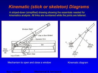
- 1. Ken Youssefi Mechanical & Aerospace 1 Kinematic (stick or skeleton) Diagrams A striped-down (simplified) drawing showing the essentials needed for kinematics analysis. All links are numbered while the joints are lettered. Mechanism to open and close a window Kinematic diagram
- 2. Ken Youssefi Mechanical & Aerospace 2 Kinematic (stick or skeleton) Diagrams
- 3. Ken Youssefi Mechanical & Aerospace 3 Kinematic (stick or skeleton) Diagrams Indicating a rigid link Indicating a fixed angle plate Hydraulic actuator
- 4. Ken Youssefi Mechanical & Aerospace 4 Degrees of Freedom An object in space has six degrees of freedom. • Translation – movement along X, Y, and Z axis (three degrees of freedom) • Rotation – rotate about X, Y, and Z axis (three degrees of freedom)
- 5. Ken Youssefi Mechanical & Aerospace 5 Degrees of Freedom (DOF) Planar (2D) mechanisms Degrees of Freedom – number of independent coordinates required to completely specify the position of the link Three independent coordinates needed to specify the location of the link AB, xA, yA, and angle θ An unconstrained link in the plane has three degrees of freedom, mechanism with L links has 3L degrees of freedom
- 6. Ken Youssefi Mechanical & Aerospace 6 Type of Joints – Kinematic Pairs Lower Pairs – motion is transmitted through an area contact, pin and slider joints. Higher Pairs – motion is transmitted through a line or a point contact; gears, rollers, and spherical joints.
- 7. Ken Youssefi Mechanical & Aerospace 7 Degrees of Freedom (DOF) – Type of Joints, Lower Pairs Each pin connection removes two degrees of freedom of relative motion between two successive links. A slider is constrained against moving in the vertical direction as well as being constrained from rotating in the plane. Two degrees of freedom joints are sometimes called a half a joint (Norton). A spheric pair is a ball and socket joint, 3 DOF. The helical pair has the sliding and rotational motion related by the helix angle of the screw. Planar pair is seldom used
- 8. Ken Youssefi Mechanical & Aerospace 8 Degrees of Freedom (DOF) – Type of Joints, Higher Pairs Roll-slide contact, 2 DOF Rolling contact (no sliding), 1 DOF Gears – sliding and rotation motion between two teeth, 2 DOF
- 9. Ken Youssefi Mechanical & Aerospace 9 Degrees of Freedom (DOF) – Type of Joints, Higher Pairs Belt and pulley (no sliding) or chain and sprocket – 1 DOF Spring – no effect on mechanism DOF
- 10. Ken Youssefi Mechanical & Aerospace 10 Degrees of Freedom (DOF) Kutzbach’s (modified Groubler) equation DOF = degree of freedom or mobility L = number of links, including ground link J1 = number of 1 DOF joints (full joints) J2 = number of 2 DOF joints (half joints) DOF ≤ 0 structure mechanismDOF > 0 DOF = 3(L – 1) – 2J1 – J2
- 11. Ken Youssefi Mechanical & Aerospace 11 Degree of Freedom (DOF) – example L = 4 , J1 = 4 pin connections, J2 = 0 DOF = 3(L – 1) – 2J1 – J2 DOF = 3(4 – 1) – 2(4) – (0) = 1 1 DOF means only one input (power source) is needed to control the mechanism L = 4 , J1 = 3 pin connections + 1 slider = 4 J2 = 0 DOF = 3(4 – 1) – 2(4) – (0) = 1 Four Bar mechanism Slider crank mechanism
- 12. Ken Youssefi Mechanical & Aerospace 12 Degrees of Freedom (DOF) – trench hoe Number of links, L = 12, Number of one DOF joints, J1 = 12 (pins) + 3 (slider) = 15, Number of two DOF joints, J2 = 0 DOF = 3(L – 1) – 2J1 – J2 = 3(12-1) -2(15) = 3 12 11 10 9 8 7 6 5 1 2 3 4 11, 12 1 2 3 4 5 6 7 8 9 10 3 hydraulics are used to control the position of the bucket.
- 13. Ken Youssefi Mechanical & Aerospace 13 Degree of Freedom (DOF) - example Number of links, L = 7, 1 1 1 2 3 4 5 6 7 Number of one DOF joints, J1 = 6 (pins) + 1 (slider) = 7, Number of two DOF joints, J2 = 1 (fork joint) DOF = 3(L – 1) – 2J1 – J2 = 3(7-1) – 2(7) – 1 = 3 Fork Joint Slider Spring Three input sources are needed to control the mechanism
- 14. Ken Youssefi Mechanical & Aerospace 14 Paradoxes Two rollers in contact, no slipping L = 3, J1 = 3, J2 = 0 DOF = 3(3-1) - 2(3) = 0 Redundant support 2 3 4 5 L = 5, J1 = 6, J2 = 0 DOF = 3(5-1) - 2(6) = 0