SlideShare une entreprise Scribd logo
1  sur  10
Télécharger pour lire hors ligne
WIND LOAD CALCULATION BASE ON EN1991-4PV SYSTEM REV.A
Calculated by:V.N.
Reviewed by: V.N.
WIND LOAD ON SURFACES (WALLS) EC-1-4
Assumptions:
Assume that structural factor cscd is equal to 1 (EN1991-1-4,cl.6.0).1.
Assume that lack of correlation of wind pressure between the windward and leeward side is2.
taken equal to 1 (EN1991-1-4,cl.7.2.2(3)).
Building data
Type of structure: PHOTOVOLTAIC SYSTEM
Total length of strucutre: d 5800mm:=
Width of structure: b 2690mm:=
Height of structure: h 3400mm:=
Spacing frame to frame: ss 2900mm:=
No of frames: No_frames 3:=
Basic values
110
WIND LOAD CALCULATION BASE ON EN1991-4PV SYSTEM REV.A
Calculated by:V.N.
Reviewed by: V.N.
Fundamental basic wind velocity
(CYS NA EN1991-1-4,fig.1):
vb.o 30m s
1-
:=
Season factor
(EN1991-1-4, NA 2.4/cl.4.2(2)):
cseason 1.0:=
Directional factor
(EN1991-1-4, NA 2.4/cl.4.2(2)):
cdir 1.0:=
Basic wind velocity
(EN1991-1-4,cl.4.2(2)):
vb cdir cseason vb.o 30 m s
1-
=:=
1.25kg m
3-
:=
Density of air:
Reference mean velocity pressure
(EN1991-1-4,cl.4.5(1)):
qb
vb
2
2
 562.5 N m
2-
=:=
Orography
Orography factor
(EN1991-1-4,cl.4.3.3(2):
co 1.0:=
Obstruction height
(EN1991-1-4,Annex A.5):
have 15m:=
Distance to the nearest adjacement
building
(EN1991-1-4,Annex A.5):
x 500m:=
Displacement height
(EN1991-1-4,Annex A.5):
hdis min 0.8 have 0.6h,( ) x 2 haveif
min 1.2 have 0.2 x- 0.6 h,( ) 2 have x< 6 have<if
0 x 6 haveif
0 m=:=
210
WIND LOAD CALCULATION BASE ON EN1991-4PV SYSTEM REV.A
Calculated by:V.N.
Reviewed by: V.N.
Terrain category
(EN1991-1-4,table 4.1):
Terrain_category "I":=
Roughness length,z0
(EN1991-1-4,table 4.1):
zo 0.003m Terrain_category "0"=if
0.01m Terrain_category "I"=if
0.05m Terrain_category "II"=if
0.3m Terrain_category "III"=if
1.0m Terrain_category "IV"=if
10 mm=:=
Roughness length,zmin
(EN1991-1-4,table 4.1): zmin 1m Terrain_category "0"=if
1m Terrain_category "I"=if
2m Terrain_category "II"=if
5m Terrain_category "III"=if
10m Terrain_category "IV"=if
1 10
3
 mm=:=
Peak wind velocity pressure
Reference height
(EN1991-4,figure 7.4)
ze h 3.4 m=:=
Maximum height
(EN1991-1-4,cl.4.3.2(1)):
zmax 200m:=
Factor, z0,II
(EN1991-4,table 4.1)
z0.II 50mm:=
310
WIND LOAD CALCULATION BASE ON EN1991-4PV SYSTEM REV.A
Calculated by:V.N.
Reviewed by: V.N.
Terrain factor
(EN1991-1-4,cl.4.3.2(1)):
kr 0.19
zo
z0.II






0.07
 0.17=:=
Roughness factor
(EN1991-1-4,cl.4.3.2(1)):
cr kr ln
zmin
zo






 0.782=:=
Mean wind velocity
(EN1991-1-4,cl.4.3.1(1)):
vm cr co vb 23.453 m s
1-
=:=
Turbulence factor
EN1991-1-4,cl.4.4(1)):
kI 1.0:=
Turbulence intensity
EN1991-1-4,cl.4.4(1)):
Iv
kI
co ln
zmin
zo







0.217=:=
Peak velocity pressure
EN1991-1-4,cl.4.5(1))::
qp 1 7 Iv+( ) 0.5  vm
2
 0.866 kN m
2-
=:=
Structural factor cscd
Assume structural factor is 1
(for buildings with a height less than 15m)
(EN1991-1-4,cl.6.2(1)):
cs.d 1:=
Wind pressure coefficients for canopy roof structure (EN1991-1-4,cl.7.3)
There is no blockage beneath the canopy, however the values of cp.net and cf have been taken
using the ϕ=0 for minimum values and ϕ=all for maximum values.
The overall force coefficient represent the resulting force. The net pressure coefficient represents
the maximum local pressure for all wind directions and have been used in the design of roofing
elements and fixing.
410
WIND LOAD CALCULATION BASE ON EN1991-4PV SYSTEM REV.A
Calculated by:V.N.
Reviewed by: V.N.
Table 1: cf values for monopitch canopies (EN1991-1-4,Table 7.6)
Wind pressures for modules 30deg
Wind suction φ=0 (max.) - Upward acting wind action
External pressure coefficient for zone A
(EN1991-1-4,Table 7.6):
cp.net.A.up.30 3.0-:=
Wind pressure for zone A
(EN1991-1-4,Eq.5.1)
we.A.up.30 qp cp.net.A.up.30 2.599- kN m
2-
=:=
510
WIND LOAD CALCULATION BASE ON EN1991-4PV SYSTEM REV.A
Calculated by:V.N.
Reviewed by: V.N.
External pressure coefficient for zone B
(EN1991-1-4,Table 7.6):
cp.net.B.up.30 3.8-:=
Wind pressure for zone B
(EN1991-1-4,Eq.5.1)
we.B.up.30 qp cp.net.B.up.30 3.292- kN m
2-
=:=
Wind suction φ=0 (max.) - Downward acting wind action
External pressure coefficient for zone A
(EN1991-1-4,Table 7.6):
cp.net.A.do.30 2.2:=
Wind pressure for zone A
(EN1991-1-4,Eq.5.1)
we.A.do.30 qp cp.net.A.do.30 1.906 kN m
2-
=:=
External pressure coefficient for zone B
(EN1991-1-4,Table 7.6):
cp.net.B.do.30 3.2:=
Wind pressure for zone B
(EN1991-1-4,Eq.5.1)
we.B.do.30 qp cp.net.B.do.30 2.772 kN m
2-
=:=
Figure 2: Location of the centre of force for monopitch canopies (EN1991-1-4,Figure 7.16)
Effective area between two
supports
Aref.mid b ss 7.801 m
2
=:=
Effective area of edges
supports
Aref.edg
Aref.mid
2
3.9 m
2
=:=
610
WIND LOAD CALCULATION BASE ON EN1991-4PV SYSTEM REV.A
Calculated by:V.N.
Reviewed by: V.N.
Wind loads for modules 30deg
Overall factor coefficient for
upward acting wind action
(EN1991-1-4,Table 7.6):
cf.up.30 1.8-:=
Overall factor coefficient for
upward acting wind action
(EN1991-1-4,Table 7.6):
cf.do.30 1.2:=
Downward acting wind force
at edge frame
(EN1991-1-4,Eq.5.3)
Fw.ed.do.30 cs.d cf.do.30 qp Aref.edg 4.055 kN=:=
Downward acting wind force
at middle frame
(EN1991-1-4,Eq.5.3)
Fw.mid.do.30 cs.d cf.do.30 qp Aref.mid 8.11 kN=:=
Upward acting wind force
at edge frame
(EN1991-1-4,Eq.5.3)
Fw.ed.up.30 cs.d cf.up.30 qp Aref.edg 6.082- kN=:=
Upward acting wind force
at middle frame
(EN1991-1-4,Eq.5.3)
Fw.mid.up.30 cs.d cf.up.30 qp Aref.mid 12.164- kN=:=
No. 4 Load cases for wind force on structure for inclination of 30deg (edge members)
b
4
0.672 m=
Fw.ed.do.30 4.055 kN= Fw.ed.do.30 4.055 kN= b
4
0.672 m=
Fw.ed.up.30 6.082- kN= Fw.ed.up.30 6.082- kN=
b
4
0.672 m=
b
4
0.672 m=
710
WIND LOAD CALCULATION BASE ON EN1991-4PV SYSTEM REV.A
Calculated by:V.N.
Reviewed by: V.N.
No. 4 Load cases for wind force on structure for inclination of 30deg (middle members)
b
4
0.672 m=
Fw.mid.do.30 8.11 kN= Fw.mid.do.30 8.11 kN= b
4
0.672 m=
Fw.mid.up.30 12.164- kN= Fw.mid.up.30 12.164- kN=
b
4
0.672 m=
b
4
0.672 m=
Frictional force on structure (EN1991-1-4,cl.7.5)
Frictional force should be considered to the roof canopy structures - see EN1991-1-4,cl.7.3.(7)
Surface type
(EN1991-1-4,Table 7.10):
Surface_type "Very rough":=
Frictional coefficient
(EN1991-1-4,Table 7.10):
cfr 0.01 Surface_type "Smooth"=if
0.02 Surface_type "Rough"=if
0.04 Surface_type "Very rough"=if
0.04=:=
Reference area: Afr 2 ss b 15.602 m
2
=:=
Frictional force per frame
(EN1991-1-4,Eq.5.7):
Ffr cfr qp
Afr
ss
 0.186 kN m
1-
=:=
810
WIND LOAD CALCULATION BASE ON EN1991-4PV SYSTEM REV.A
Calculated by:V.N.
Reviewed by: V.N.
910
WIND LOAD CALCULATION BASE ON EN1991-4PV SYSTEM REV.A
Calculated by:V.N.
Reviewed by: V.N.
1010

Contenu connexe

Tendances

Rc corbel example
Rc corbel exampleRc corbel example
Rc corbel example
mamilli
 
Steel Warehouse Project
Steel Warehouse ProjectSteel Warehouse Project
Steel Warehouse Project
Jawad Shaukat
 

Tendances (20)

ETABS manual - Seismic design of steel buildings according to Eurocode 3 & 8
ETABS manual - Seismic design of steel buildings according to Eurocode 3 & 8 ETABS manual - Seismic design of steel buildings according to Eurocode 3 & 8
ETABS manual - Seismic design of steel buildings according to Eurocode 3 & 8
 
23-Design of Column Base Plates (Steel Structural Design & Prof. Shehab Mourad)
23-Design of Column Base Plates (Steel Structural Design & Prof. Shehab Mourad)23-Design of Column Base Plates (Steel Structural Design & Prof. Shehab Mourad)
23-Design of Column Base Plates (Steel Structural Design & Prof. Shehab Mourad)
 
ETABS Modelling
ETABS ModellingETABS Modelling
ETABS Modelling
 
22-Design of Four Bolt Extended Endplate Connection (Steel Structural Design ...
22-Design of Four Bolt Extended Endplate Connection (Steel Structural Design ...22-Design of Four Bolt Extended Endplate Connection (Steel Structural Design ...
22-Design of Four Bolt Extended Endplate Connection (Steel Structural Design ...
 
21-Design of Simple Shear Connections (Steel Structural Design & Prof. Shehab...
21-Design of Simple Shear Connections (Steel Structural Design & Prof. Shehab...21-Design of Simple Shear Connections (Steel Structural Design & Prof. Shehab...
21-Design of Simple Shear Connections (Steel Structural Design & Prof. Shehab...
 
Seismic Design Of Structures Project
Seismic Design Of Structures ProjectSeismic Design Of Structures Project
Seismic Design Of Structures Project
 
Rc corbel example
Rc corbel exampleRc corbel example
Rc corbel example
 
Chimney design
Chimney designChimney design
Chimney design
 
Chapter 1
Chapter 1Chapter 1
Chapter 1
 
Lecture 1 design loads
Lecture 1   design loadsLecture 1   design loads
Lecture 1 design loads
 
Anchor bolt design
Anchor bolt designAnchor bolt design
Anchor bolt design
 
Tutorial #2 - SACS Basic
Tutorial #2 - SACS BasicTutorial #2 - SACS Basic
Tutorial #2 - SACS Basic
 
Wind loading
Wind loadingWind loading
Wind loading
 
variation of wind load with height & aspect ratio
variation of wind load with height & aspect ratiovariation of wind load with height & aspect ratio
variation of wind load with height & aspect ratio
 
Lecture 4 5 Urm Shear Walls
Lecture 4 5 Urm Shear WallsLecture 4 5 Urm Shear Walls
Lecture 4 5 Urm Shear Walls
 
Machine Foundation Design
Machine Foundation Design Machine Foundation Design
Machine Foundation Design
 
Design calculations of raft foundation
Design calculations of raft foundationDesign calculations of raft foundation
Design calculations of raft foundation
 
Steel Warehouse Project
Steel Warehouse ProjectSteel Warehouse Project
Steel Warehouse Project
 
WIND CODE-IS 875-PART 3
WIND CODE-IS 875-PART 3WIND CODE-IS 875-PART 3
WIND CODE-IS 875-PART 3
 
Sachpazis: Wind loading to EN 1991 1-4- for a hipped roof example
Sachpazis: Wind loading to EN 1991 1-4- for a hipped roof exampleSachpazis: Wind loading to EN 1991 1-4- for a hipped roof example
Sachpazis: Wind loading to EN 1991 1-4- for a hipped roof example
 

En vedette

Design.guide.post tensioned.concrete.floors-cps
Design.guide.post tensioned.concrete.floors-cpsDesign.guide.post tensioned.concrete.floors-cps
Design.guide.post tensioned.concrete.floors-cps
Luan Truong Van
 
Lecture 6 steel building design considering earthquake and wind load
Lecture 6 steel building design considering earthquake and wind loadLecture 6 steel building design considering earthquake and wind load
Lecture 6 steel building design considering earthquake and wind load
Dr. H.M.A. Mahzuz
 
Lecture 5 rcc building design considering earthquake and wind load
Lecture 5 rcc building design considering earthquake and wind loadLecture 5 rcc building design considering earthquake and wind load
Lecture 5 rcc building design considering earthquake and wind load
Dr. H.M.A. Mahzuz
 
A Picture Album of the Finite Element Method
A Picture Album of the Finite Element MethodA Picture Album of the Finite Element Method
A Picture Album of the Finite Element Method
Rahul Leslie
 

En vedette (20)

Simplified notes of calculate Wind & Snow loads based on CYS EC1
Simplified notes of calculate Wind & Snow loads based on CYS EC1Simplified notes of calculate Wind & Snow loads based on CYS EC1
Simplified notes of calculate Wind & Snow loads based on CYS EC1
 
PORTFOLIO-Model
PORTFOLIO-ModelPORTFOLIO-Model
PORTFOLIO-Model
 
DETAILED CV - Aug 16 v3
DETAILED CV - Aug 16 v3DETAILED CV - Aug 16 v3
DETAILED CV - Aug 16 v3
 
Seismic assessment of buildings accordance to Eurocode 8 Part 3
Seismic assessment of buildings accordance to Eurocode 8 Part 3Seismic assessment of buildings accordance to Eurocode 8 Part 3
Seismic assessment of buildings accordance to Eurocode 8 Part 3
 
Etabs modelling parameters
Etabs modelling parametersEtabs modelling parameters
Etabs modelling parameters
 
Loadings snow - wind
Loadings   snow - windLoadings   snow - wind
Loadings snow - wind
 
STRUCTURAL DESIGN OF PIPE CULVERT TO BS EN 1295-1
STRUCTURAL DESIGN OF PIPE CULVERT TO BS EN 1295-1STRUCTURAL DESIGN OF PIPE CULVERT TO BS EN 1295-1
STRUCTURAL DESIGN OF PIPE CULVERT TO BS EN 1295-1
 
Etabs modeling - Design of slab according to EC2
Etabs modeling  - Design of slab according to EC2Etabs modeling  - Design of slab according to EC2
Etabs modeling - Design of slab according to EC2
 
Rubblization
RubblizationRubblization
Rubblization
 
THEORY 1 : V & M diagrams
THEORY 1 : V & M diagramsTHEORY 1 : V & M diagrams
THEORY 1 : V & M diagrams
 
Wri 03 forcesstaticfluids
Wri 03 forcesstaticfluidsWri 03 forcesstaticfluids
Wri 03 forcesstaticfluids
 
Lecture earthquake-2
Lecture earthquake-2Lecture earthquake-2
Lecture earthquake-2
 
Design.guide.post tensioned.concrete.floors-cps
Design.guide.post tensioned.concrete.floors-cpsDesign.guide.post tensioned.concrete.floors-cps
Design.guide.post tensioned.concrete.floors-cps
 
Psychological firstaid 1
Psychological firstaid   1Psychological firstaid   1
Psychological firstaid 1
 
Lecture 6 steel building design considering earthquake and wind load
Lecture 6 steel building design considering earthquake and wind loadLecture 6 steel building design considering earthquake and wind load
Lecture 6 steel building design considering earthquake and wind load
 
Rural water supply volume iii operation and maintenance manual
Rural water supply volume iii   operation and maintenance manualRural water supply volume iii   operation and maintenance manual
Rural water supply volume iii operation and maintenance manual
 
Lecture 5 rcc building design considering earthquake and wind load
Lecture 5 rcc building design considering earthquake and wind loadLecture 5 rcc building design considering earthquake and wind load
Lecture 5 rcc building design considering earthquake and wind load
 
A Picture Album of the Finite Element Method
A Picture Album of the Finite Element MethodA Picture Album of the Finite Element Method
A Picture Album of the Finite Element Method
 
Some fun facts
Some fun factsSome fun facts
Some fun facts
 
trusses
trussestrusses
trusses
 

Similaire à Wind load on pv system

1 a. Design of hording structures.pptx
1 a. Design of hording structures.pptx1 a. Design of hording structures.pptx
1 a. Design of hording structures.pptx
NayanDhake4
 
Presentation Wind and Eurocode UK
Presentation Wind and Eurocode UKPresentation Wind and Eurocode UK
Presentation Wind and Eurocode UK
Abdurahman Ahmed
 

Similaire à Wind load on pv system (20)

COMPARISON BETWEEN VARIOUS STEEL SECTION BY USING IS CODE AND EURO CODE
COMPARISON BETWEEN VARIOUS STEEL SECTION BY USING IS CODE AND EURO CODECOMPARISON BETWEEN VARIOUS STEEL SECTION BY USING IS CODE AND EURO CODE
COMPARISON BETWEEN VARIOUS STEEL SECTION BY USING IS CODE AND EURO CODE
 
FE Analysis of Bolted Connections for Wind Turbine Towers by Yadneshwar S. Joshi
FE Analysis of Bolted Connections for Wind Turbine Towers by Yadneshwar S. JoshiFE Analysis of Bolted Connections for Wind Turbine Towers by Yadneshwar S. Joshi
FE Analysis of Bolted Connections for Wind Turbine Towers by Yadneshwar S. Joshi
 
4998 1
4998 14998 1
4998 1
 
Wind-Analysis-Building Sdas.ppt
Wind-Analysis-Building Sdas.pptWind-Analysis-Building Sdas.ppt
Wind-Analysis-Building Sdas.ppt
 
Wind analysis of building
Wind analysis of buildingWind analysis of building
Wind analysis of building
 
Chimney design &amp;engg code
Chimney design &amp;engg codeChimney design &amp;engg code
Chimney design &amp;engg code
 
Wind loads
Wind loadsWind loads
Wind loads
 
Design of housing apartment
Design of  housing apartmentDesign of  housing apartment
Design of housing apartment
 
Cha 1 powerpoint.pdf
Cha 1 powerpoint.pdfCha 1 powerpoint.pdf
Cha 1 powerpoint.pdf
 
Transmission and distribution line design final
Transmission and distribution line design finalTransmission and distribution line design final
Transmission and distribution line design final
 
Sachpazis_Wind Loading (EN1991-1-4) for a Duopitch roof example_Apr-2017
Sachpazis_Wind Loading (EN1991-1-4) for a Duopitch roof example_Apr-2017Sachpazis_Wind Loading (EN1991-1-4) for a Duopitch roof example_Apr-2017
Sachpazis_Wind Loading (EN1991-1-4) for a Duopitch roof example_Apr-2017
 
Chapter 1-types of structures and loads
Chapter 1-types of structures and loadsChapter 1-types of structures and loads
Chapter 1-types of structures and loads
 
CHAPTER 3 (part 1) Wind Load and procedure.pptx
CHAPTER 3 (part 1) Wind Load and procedure.pptxCHAPTER 3 (part 1) Wind Load and procedure.pptx
CHAPTER 3 (part 1) Wind Load and procedure.pptx
 
Ycef presentaion derivation of wind loading upload
Ycef presentaion derivation of wind loading uploadYcef presentaion derivation of wind loading upload
Ycef presentaion derivation of wind loading upload
 
1 a. Design of hording structures.pptx
1 a. Design of hording structures.pptx1 a. Design of hording structures.pptx
1 a. Design of hording structures.pptx
 
Importance of Eccentric Wind Loading on Monopitch Module Mounting Structures
Importance of Eccentric Wind Loading on Monopitch Module Mounting StructuresImportance of Eccentric Wind Loading on Monopitch Module Mounting Structures
Importance of Eccentric Wind Loading on Monopitch Module Mounting Structures
 
Design of manual solar tracking system wps
Design of manual solar tracking system wpsDesign of manual solar tracking system wps
Design of manual solar tracking system wps
 
CFD Analysis for Computing Drag force on Various types of blades for Vertical...
CFD Analysis for Computing Drag force on Various types of blades for Vertical...CFD Analysis for Computing Drag force on Various types of blades for Vertical...
CFD Analysis for Computing Drag force on Various types of blades for Vertical...
 
Presentation Wind and Eurocode UK
Presentation Wind and Eurocode UKPresentation Wind and Eurocode UK
Presentation Wind and Eurocode UK
 
Design of Tall Vessels (Distillation columns)
Design of Tall Vessels (Distillation columns)Design of Tall Vessels (Distillation columns)
Design of Tall Vessels (Distillation columns)
 

Dernier

01-vogelsanger-stanag-4178-ed-2-the-new-nato-standard-for-nitrocellulose-test...
01-vogelsanger-stanag-4178-ed-2-the-new-nato-standard-for-nitrocellulose-test...01-vogelsanger-stanag-4178-ed-2-the-new-nato-standard-for-nitrocellulose-test...
01-vogelsanger-stanag-4178-ed-2-the-new-nato-standard-for-nitrocellulose-test...
AshwaniAnuragi1
 
1_Introduction + EAM Vocabulary + how to navigate in EAM.pdf
1_Introduction + EAM Vocabulary + how to navigate in EAM.pdf1_Introduction + EAM Vocabulary + how to navigate in EAM.pdf
1_Introduction + EAM Vocabulary + how to navigate in EAM.pdf
AldoGarca30
 
Degrees of freedom for the robots 1.pptx
Degrees of freedom for the robots 1.pptxDegrees of freedom for the robots 1.pptx
Degrees of freedom for the robots 1.pptx
Mostafa Mahmoud
 
21P35A0312 Internship eccccccReport.docx
21P35A0312 Internship eccccccReport.docx21P35A0312 Internship eccccccReport.docx
21P35A0312 Internship eccccccReport.docx
rahulmanepalli02
 

Dernier (20)

Autodesk Construction Cloud (Autodesk Build).pptx
Autodesk Construction Cloud (Autodesk Build).pptxAutodesk Construction Cloud (Autodesk Build).pptx
Autodesk Construction Cloud (Autodesk Build).pptx
 
Introduction to Artificial Intelligence ( AI)
Introduction to Artificial Intelligence ( AI)Introduction to Artificial Intelligence ( AI)
Introduction to Artificial Intelligence ( AI)
 
Dr Mrs A A Miraje C Programming PPT.pptx
Dr Mrs A A Miraje C Programming PPT.pptxDr Mrs A A Miraje C Programming PPT.pptx
Dr Mrs A A Miraje C Programming PPT.pptx
 
Circuit Breakers for Engineering Students
Circuit Breakers for Engineering StudentsCircuit Breakers for Engineering Students
Circuit Breakers for Engineering Students
 
Databricks Generative AI Fundamentals .pdf
Databricks Generative AI Fundamentals  .pdfDatabricks Generative AI Fundamentals  .pdf
Databricks Generative AI Fundamentals .pdf
 
Worksharing and 3D Modeling with Revit.pptx
Worksharing and 3D Modeling with Revit.pptxWorksharing and 3D Modeling with Revit.pptx
Worksharing and 3D Modeling with Revit.pptx
 
Overview of Transformation in Computer Graphics
Overview of Transformation in Computer GraphicsOverview of Transformation in Computer Graphics
Overview of Transformation in Computer Graphics
 
01-vogelsanger-stanag-4178-ed-2-the-new-nato-standard-for-nitrocellulose-test...
01-vogelsanger-stanag-4178-ed-2-the-new-nato-standard-for-nitrocellulose-test...01-vogelsanger-stanag-4178-ed-2-the-new-nato-standard-for-nitrocellulose-test...
01-vogelsanger-stanag-4178-ed-2-the-new-nato-standard-for-nitrocellulose-test...
 
1_Introduction + EAM Vocabulary + how to navigate in EAM.pdf
1_Introduction + EAM Vocabulary + how to navigate in EAM.pdf1_Introduction + EAM Vocabulary + how to navigate in EAM.pdf
1_Introduction + EAM Vocabulary + how to navigate in EAM.pdf
 
Call for Papers - Journal of Electrical Systems (JES), E-ISSN: 1112-5209, ind...
Call for Papers - Journal of Electrical Systems (JES), E-ISSN: 1112-5209, ind...Call for Papers - Journal of Electrical Systems (JES), E-ISSN: 1112-5209, ind...
Call for Papers - Journal of Electrical Systems (JES), E-ISSN: 1112-5209, ind...
 
Dynamo Scripts for Task IDs and Space Naming.pptx
Dynamo Scripts for Task IDs and Space Naming.pptxDynamo Scripts for Task IDs and Space Naming.pptx
Dynamo Scripts for Task IDs and Space Naming.pptx
 
Degrees of freedom for the robots 1.pptx
Degrees of freedom for the robots 1.pptxDegrees of freedom for the robots 1.pptx
Degrees of freedom for the robots 1.pptx
 
handbook on reinforce concrete and detailing
handbook on reinforce concrete and detailinghandbook on reinforce concrete and detailing
handbook on reinforce concrete and detailing
 
Study of Computer Hardware System using Block Diagram
Study of Computer Hardware System using Block DiagramStudy of Computer Hardware System using Block Diagram
Study of Computer Hardware System using Block Diagram
 
21P35A0312 Internship eccccccReport.docx
21P35A0312 Internship eccccccReport.docx21P35A0312 Internship eccccccReport.docx
21P35A0312 Internship eccccccReport.docx
 
History of Indian Railways - the story of Growth & Modernization
History of Indian Railways - the story of Growth & ModernizationHistory of Indian Railways - the story of Growth & Modernization
History of Indian Railways - the story of Growth & Modernization
 
Involute of a circle,Square, pentagon,HexagonInvolute_Engineering Drawing.pdf
Involute of a circle,Square, pentagon,HexagonInvolute_Engineering Drawing.pdfInvolute of a circle,Square, pentagon,HexagonInvolute_Engineering Drawing.pdf
Involute of a circle,Square, pentagon,HexagonInvolute_Engineering Drawing.pdf
 
Fundamentals of Structure in C Programming
Fundamentals of Structure in C ProgrammingFundamentals of Structure in C Programming
Fundamentals of Structure in C Programming
 
Independent Solar-Powered Electric Vehicle Charging Station
Independent Solar-Powered Electric Vehicle Charging StationIndependent Solar-Powered Electric Vehicle Charging Station
Independent Solar-Powered Electric Vehicle Charging Station
 
Danikor Product Catalog- Screw Feeder.pdf
Danikor Product Catalog- Screw Feeder.pdfDanikor Product Catalog- Screw Feeder.pdf
Danikor Product Catalog- Screw Feeder.pdf
 

Wind load on pv system

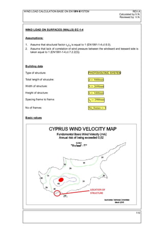
  • 1. WIND LOAD CALCULATION BASE ON EN1991-4PV SYSTEM REV.A Calculated by:V.N. Reviewed by: V.N. WIND LOAD ON SURFACES (WALLS) EC-1-4 Assumptions: Assume that structural factor cscd is equal to 1 (EN1991-1-4,cl.6.0).1. Assume that lack of correlation of wind pressure between the windward and leeward side is2. taken equal to 1 (EN1991-1-4,cl.7.2.2(3)). Building data Type of structure: PHOTOVOLTAIC SYSTEM Total length of strucutre: d 5800mm:= Width of structure: b 2690mm:= Height of structure: h 3400mm:= Spacing frame to frame: ss 2900mm:= No of frames: No_frames 3:= Basic values 110
  • 2. WIND LOAD CALCULATION BASE ON EN1991-4PV SYSTEM REV.A Calculated by:V.N. Reviewed by: V.N. Fundamental basic wind velocity (CYS NA EN1991-1-4,fig.1): vb.o 30m s 1- := Season factor (EN1991-1-4, NA 2.4/cl.4.2(2)): cseason 1.0:= Directional factor (EN1991-1-4, NA 2.4/cl.4.2(2)): cdir 1.0:= Basic wind velocity (EN1991-1-4,cl.4.2(2)): vb cdir cseason vb.o 30 m s 1- =:= 1.25kg m 3- := Density of air: Reference mean velocity pressure (EN1991-1-4,cl.4.5(1)): qb vb 2 2  562.5 N m 2- =:= Orography Orography factor (EN1991-1-4,cl.4.3.3(2): co 1.0:= Obstruction height (EN1991-1-4,Annex A.5): have 15m:= Distance to the nearest adjacement building (EN1991-1-4,Annex A.5): x 500m:= Displacement height (EN1991-1-4,Annex A.5): hdis min 0.8 have 0.6h,( ) x 2 haveif min 1.2 have 0.2 x- 0.6 h,( ) 2 have x< 6 have<if 0 x 6 haveif 0 m=:= 210
  • 3. WIND LOAD CALCULATION BASE ON EN1991-4PV SYSTEM REV.A Calculated by:V.N. Reviewed by: V.N. Terrain category (EN1991-1-4,table 4.1): Terrain_category "I":= Roughness length,z0 (EN1991-1-4,table 4.1): zo 0.003m Terrain_category "0"=if 0.01m Terrain_category "I"=if 0.05m Terrain_category "II"=if 0.3m Terrain_category "III"=if 1.0m Terrain_category "IV"=if 10 mm=:= Roughness length,zmin (EN1991-1-4,table 4.1): zmin 1m Terrain_category "0"=if 1m Terrain_category "I"=if 2m Terrain_category "II"=if 5m Terrain_category "III"=if 10m Terrain_category "IV"=if 1 10 3  mm=:= Peak wind velocity pressure Reference height (EN1991-4,figure 7.4) ze h 3.4 m=:= Maximum height (EN1991-1-4,cl.4.3.2(1)): zmax 200m:= Factor, z0,II (EN1991-4,table 4.1) z0.II 50mm:= 310
  • 4. WIND LOAD CALCULATION BASE ON EN1991-4PV SYSTEM REV.A Calculated by:V.N. Reviewed by: V.N. Terrain factor (EN1991-1-4,cl.4.3.2(1)): kr 0.19 zo z0.II       0.07  0.17=:= Roughness factor (EN1991-1-4,cl.4.3.2(1)): cr kr ln zmin zo        0.782=:= Mean wind velocity (EN1991-1-4,cl.4.3.1(1)): vm cr co vb 23.453 m s 1- =:= Turbulence factor EN1991-1-4,cl.4.4(1)): kI 1.0:= Turbulence intensity EN1991-1-4,cl.4.4(1)): Iv kI co ln zmin zo        0.217=:= Peak velocity pressure EN1991-1-4,cl.4.5(1)):: qp 1 7 Iv+( ) 0.5  vm 2  0.866 kN m 2- =:= Structural factor cscd Assume structural factor is 1 (for buildings with a height less than 15m) (EN1991-1-4,cl.6.2(1)): cs.d 1:= Wind pressure coefficients for canopy roof structure (EN1991-1-4,cl.7.3) There is no blockage beneath the canopy, however the values of cp.net and cf have been taken using the ϕ=0 for minimum values and ϕ=all for maximum values. The overall force coefficient represent the resulting force. The net pressure coefficient represents the maximum local pressure for all wind directions and have been used in the design of roofing elements and fixing. 410
  • 5. WIND LOAD CALCULATION BASE ON EN1991-4PV SYSTEM REV.A Calculated by:V.N. Reviewed by: V.N. Table 1: cf values for monopitch canopies (EN1991-1-4,Table 7.6) Wind pressures for modules 30deg Wind suction φ=0 (max.) - Upward acting wind action External pressure coefficient for zone A (EN1991-1-4,Table 7.6): cp.net.A.up.30 3.0-:= Wind pressure for zone A (EN1991-1-4,Eq.5.1) we.A.up.30 qp cp.net.A.up.30 2.599- kN m 2- =:= 510
  • 6. WIND LOAD CALCULATION BASE ON EN1991-4PV SYSTEM REV.A Calculated by:V.N. Reviewed by: V.N. External pressure coefficient for zone B (EN1991-1-4,Table 7.6): cp.net.B.up.30 3.8-:= Wind pressure for zone B (EN1991-1-4,Eq.5.1) we.B.up.30 qp cp.net.B.up.30 3.292- kN m 2- =:= Wind suction φ=0 (max.) - Downward acting wind action External pressure coefficient for zone A (EN1991-1-4,Table 7.6): cp.net.A.do.30 2.2:= Wind pressure for zone A (EN1991-1-4,Eq.5.1) we.A.do.30 qp cp.net.A.do.30 1.906 kN m 2- =:= External pressure coefficient for zone B (EN1991-1-4,Table 7.6): cp.net.B.do.30 3.2:= Wind pressure for zone B (EN1991-1-4,Eq.5.1) we.B.do.30 qp cp.net.B.do.30 2.772 kN m 2- =:= Figure 2: Location of the centre of force for monopitch canopies (EN1991-1-4,Figure 7.16) Effective area between two supports Aref.mid b ss 7.801 m 2 =:= Effective area of edges supports Aref.edg Aref.mid 2 3.9 m 2 =:= 610
  • 7. WIND LOAD CALCULATION BASE ON EN1991-4PV SYSTEM REV.A Calculated by:V.N. Reviewed by: V.N. Wind loads for modules 30deg Overall factor coefficient for upward acting wind action (EN1991-1-4,Table 7.6): cf.up.30 1.8-:= Overall factor coefficient for upward acting wind action (EN1991-1-4,Table 7.6): cf.do.30 1.2:= Downward acting wind force at edge frame (EN1991-1-4,Eq.5.3) Fw.ed.do.30 cs.d cf.do.30 qp Aref.edg 4.055 kN=:= Downward acting wind force at middle frame (EN1991-1-4,Eq.5.3) Fw.mid.do.30 cs.d cf.do.30 qp Aref.mid 8.11 kN=:= Upward acting wind force at edge frame (EN1991-1-4,Eq.5.3) Fw.ed.up.30 cs.d cf.up.30 qp Aref.edg 6.082- kN=:= Upward acting wind force at middle frame (EN1991-1-4,Eq.5.3) Fw.mid.up.30 cs.d cf.up.30 qp Aref.mid 12.164- kN=:= No. 4 Load cases for wind force on structure for inclination of 30deg (edge members) b 4 0.672 m= Fw.ed.do.30 4.055 kN= Fw.ed.do.30 4.055 kN= b 4 0.672 m= Fw.ed.up.30 6.082- kN= Fw.ed.up.30 6.082- kN= b 4 0.672 m= b 4 0.672 m= 710
  • 8. WIND LOAD CALCULATION BASE ON EN1991-4PV SYSTEM REV.A Calculated by:V.N. Reviewed by: V.N. No. 4 Load cases for wind force on structure for inclination of 30deg (middle members) b 4 0.672 m= Fw.mid.do.30 8.11 kN= Fw.mid.do.30 8.11 kN= b 4 0.672 m= Fw.mid.up.30 12.164- kN= Fw.mid.up.30 12.164- kN= b 4 0.672 m= b 4 0.672 m= Frictional force on structure (EN1991-1-4,cl.7.5) Frictional force should be considered to the roof canopy structures - see EN1991-1-4,cl.7.3.(7) Surface type (EN1991-1-4,Table 7.10): Surface_type "Very rough":= Frictional coefficient (EN1991-1-4,Table 7.10): cfr 0.01 Surface_type "Smooth"=if 0.02 Surface_type "Rough"=if 0.04 Surface_type "Very rough"=if 0.04=:= Reference area: Afr 2 ss b 15.602 m 2 =:= Frictional force per frame (EN1991-1-4,Eq.5.7): Ffr cfr qp Afr ss  0.186 kN m 1- =:= 810
  • 9. WIND LOAD CALCULATION BASE ON EN1991-4PV SYSTEM REV.A Calculated by:V.N. Reviewed by: V.N. 910
  • 10. WIND LOAD CALCULATION BASE ON EN1991-4PV SYSTEM REV.A Calculated by:V.N. Reviewed by: V.N. 1010