SlideShare une entreprise Scribd logo
1  sur  17
Télécharger pour lire hors ligne
OUTPUT              PENTODE

Output    pentode   rated   for 25W          anode dissipation,
ntended    for use in a.c. mains         operated    equipment.


                                        PRELIMINARY               DATA

HEATER
                                 Vh                                                    6.3       v
                                 Ih                                                    1.5       A


CAPACITANCES
                                 Cout                                                  7.2      pF
                                 Cln                                                  15.5      pF
                                 C&-gl                                               <1.1       pF
                                 Cgl-h                                               <1.0       pF
                                 Ck-h                                                 11        pF


CHARACTERISTICS
                                 Va                                                  250          v
                                 v go                                                250          v
                                 Vgs                                                    0         v
                                 la                                                  100      mA
                                 Igo                                                   14.9   mA
                                 Vgl                                                 -13.5        V
                                 gm                                                    11   mA/V
                                 ra                                                   15       kil
                                 (.I.gl-gO                                             11


OPERATING            CONDITIONS                     AS SINGLE        VALVE   CLASS   "A"
AMPLIFIER
     Pentode        connection
                               Va                                                    250        V
                               Vg2                                                   250         V
                               Vga                                                     0        V
                               Vg1                                                   -13.5      V
                               Rk                                                    120        (1
                               la                                                    100       mA
                               Ig2                                                    14.9     mA
                               R.                                                      2.0     k(1
                               V1n (r.m.B.) (Pout=50mW)                                0.5       V
                              *Pout                                                   11        W
                               V1n (r.m.B.)                                            8.7       V
                              *Dtot                                                   10        %

                *Pout and Dtot are measured at fixed bias and therefore represent the
                 power output available during the reproduction of speech and music.
                 When a sustained sine wave is applied to the control grid the bias
                 across the cathode resistor will readjust itself as a result of the
                 increased anode and screen-grid      currents.   This will result in
                 approximately   10% reduction in power output.


ISSUE 2                                                                                 EL34 256-1
OUTPUT               PENTODE

                                                     Output        pentode          roted   for 2SW      onode dissipotion,
                                                     intended       for use in a.c. mains           operated       equiPment.


OPERATING              CONDITIONS                           FOR     TWO                VALVES       IN     PUSH-PULL

          Distributed       load        conditions                with      screen-grid           tapping         at 43% of
          primary     turns

                                V"J-VRk                                                  430                   430          v
                                   Rg2      (per     valve)                                 1                       1      kO
                                Vg2+VRk                                                   425                  425           V
                                   18(0)                                               2 x 62.5             2 x 62.5       mA
                                   18 (max.         sig.)                              2x65                 2x70           mA
                                   Ig2(0)                                               2x5.0                2x5.0         mA
                                   Ig2 (max.         sig.)                              2x5.1                2x7.5         mA
                                   Rk      (per     valve)                                470                  470          O
                                V1n(gl-gl)           r.m...                                32                     52        V
                                   R8-8                                                     6.6                     6.6    kO
                                   Pout                                                    20                     37        W
                                Dtot                                                        0.8                     1.3     %


OPERATING              CONDITIONS                       FOR         TWO             VALVES         IN     PUSH.PULL
          Fixed bias

                                Vb                                         425                                375           y
                               "Rg2                                       1000                                470           O
                                Vg2                                             0                                  0        y
                                18(0)                                    2x30                              2x35            mA
                                   la (max.         sig.)           2x120                                 2x120            mA
                                Ig2 (0)                                   2x4.4                             2x4.7          mA
                                Ig2 (max.            sig.)           2x25                                  2x25            mA
                                Vg1                                        -38                                -32           y
                                R8-a                                             3.4                               2.8     kO
                                V1n (gi-g          11 r.m.8.                54                                 45           y
                                Pout                                        55                                 44          W
                                Dtot                                             5.0                               5.0      %

                *Screen-grid        resistor         common to both valves,

                  These operating conditions apply with a stabilised line voltage and
                  allow for a 25V drop in the primary winding of the output trans-
                  former at maximum signal. If there is an additional drop of 25V
                  in the h.t. line voltage at maximum signal Pout=45W and 36W.
                  The optimum     anode-to-anode  load under these conditions     are
                  4.0kD. and 3.8kD. respectively.


ISSUE 2                                                                                                             EL34 256-2
OUTPUT                PENTODE

Output     pentode    rated   forc25W   anode dissipation,
intended    for use in a.c. mains operated     equipment


OPERATING               CONDITIONS            FOR     TWO    VALVES   IN   PUSH-PULL
     With     separate screen-grid supply and fixed bias
                            Vb(a)                  500                       800        V
                            Vb(g2'                 400                       400        V
                           *Rg2                    750                       750        !1
                             Vg:J                     0                         0        V
                             Ja(O;               2x30                      2x25        mA
                             la (max. sig.)     2x125                      2x91        mA
                             Ig2(o,               2x4.0                     2x3.0      mA
                             Ig2 (max:sig.)      2x25                      2x19        mA
                             Vg1                   -36                       -39         V
                             Ra_a                     4.0                      11      k!1
                             VIR (g,-g,) r.m.B.      51                       47         V
                          , PC))1~                   70                      100        W
                       I     Dto1                     5.0                       5.0     %
                                               ,
                *Screen-grid       resistor common to both valves.
                     These operating conditions apply with stabilised line voltages and
                     allow for a 2SV drop in the primary winding of the output trans-
                     former at maximum signal.     If there is an additional drop of 25V
                     in the line voltages at maximum signal Pout=58W and 90W.        The
                     optimum anode-to-anode     load under these conditions are 5.0k!1
                     and 11 kO respectively.


OPERATING               CONDITIONS            FOR     TWO    VALVES   IN   PUSH.PULL
     Cathode         bias
                                 Vb                                           375       V
                                *Rg.                                          470       O
                                tRk                                           130       O
                                 Vg.                                            O        V
                                 la(ol                                     2x75        mA
                                 la(max.sig.)                              2x95        mA
                                 Ig.(ol                                    2x11.5      mA
                                 In (max.c5jgr) !                          2 x 22.5    mA
                                 Ra_a                                           3.4    kO
                                 V1n(gl-gl) r.m.8.                             42        V
                                 Pout                                          35       W
                                 Dtot                                           5.0     %

                 *Screen-grid      resistor common tO both valves.
                 tCommon        cathode bias resistor.
                     These operating conditions allow for a 20V drop in the primary
                     winding of the output transformer  and a 5V drop in the h.t. line
                     voltage at maximum signal.


ISSUE 2                                                                        EL34 1056.3
OUTPUT              PENTODE

                                       Output     pentode   rated   far 25W      anode dissipation,
                                       intended    for use in a.c. mains    operated    equipment.


OPERATING          CONDITIONS              AS      SINGLE           VALVE         CLASS        "A"
AMPLIFIER

    Triode    connection      (g2 connected to a, ga to k)

                            Va+VRk                                                   375           v
                            V                                                           0          v
                            R~a                                                      370          O
                            la                                                         70        mA
                            Vgl                                                      -26           V
                            Ra                                                          3.0      kO
                            V1n (r.m.s.) (Poul=50mW)                                    1.7        V
                            Poul                                                        6.0       W
                            V1n (r.m.s.)                                               18.9        V
                            Dlo1                                                        8.0       %


OPERATING         CONDITIONS            FOR       TWO       VALVES          IN     PUSH-PULL
     Triode   connection      (g2 connected to a, g3 to k)
                            V,,+VRk                   400                             430          V
                            V83                          0                              0          V
                           *Rk                        220                           t250          .0
                            I,,(o)                  2x65                           2x64          mA
                            I" (max. sig.)          2x71                           2x67          mA
                            V81                       -29                            -32           V
                            R"_,,                        5.0                           10        k.O
                            V1n (81-81)r.m.s.          44                              48          V
                            Poul                        16                             14         W
                            D1o1                         3.0                          <1.0        %
              *Common      cathode bias resistor.

              tUn-bypassed.


LIMITING       VALUES
                            Va(b) max.                                                  2.0          kV
                            Va max.                                                  800              V
                            Pa max.                                                   25             W
                            Pa max. (max. signal speech and music)                    27.5           W
                            V lI(b) max.                                             800              V
                            VII max.                                                 425              V
                            pgo max.                                                    8.0          W
                            Ik max.                                                  150        mA
                            Vn max. (In=+0.3!J.A)                                     -1.3            V
                            Rn-k max. (cathode bias)                                 700         k.Q
                            Rn-k max. (fixed bias)                                   500         k.Q
                            Vh-k max.                                                100              V
                            Rh-k max.                                                 20         k.Q


ISSUE 2                                                                                EL34 1056.4
OUTPUT               PENTODE

Output     pentode   roted   for 2SW   anode dissipation,
intended    for use in a.c. mains    operated       equipment.


 ~


                                                92         91


                                        a                        HC

                                q2

                                        h                        h

                                                q3          k

                                                Oclal Bas,


ISSUE2                                                                EL3~ 1056-5
                                                ~
OUTPUT               PENTODE

                               Output     pentode   rated   for 25W     anode    dissiPation,
                               intended    for use in a.c. mains      operated    equiPment.


ANODE     AND   SCREEN-GRID    CURRENT   PLOTTED              AGAINST            CONTROL
                              GRID VOLTAGE


ISSUS;2                                                                          EL34   1056-6
OUTPUT                PENTODE

Output     pentode    roted          for 25W   onode     dissipation,
intended    for use in a.c. mains          operated      equiPment.


  ~                                                                         ~
  0-                                                                        I


                               >               >
                       ."'
                               O               "i'
                       """
                       -'      "
                       ..."'
                               ::'


                     >
                     O
                      II


                                                                                                   I~
           ,0.:~..


                                                                                               0
  a..
  HE           ~                                     ~

  ANODE        CURRENT                  PLOTTED           AGAINST       ANODE   VOLTAGE       WITH
               CONTROL-GRID                    VOLTAGE           AS PARAMETER   Vg.=250V


ISSUE 2
                                                         @                                 EL34 357.7
OUTPUT            PENTODE-

                           Output     pentode   rated   for 25W   anode dissipation,
                           intended    for use in a.c. mains   operated   equipment.


  ANODE     CURRENT   PLOTTED AGAINST ANODE   VOLTAGE                       WITH
          CONTROL   GRID VOLTAGE AS PARAMETER Vg2=360V


                cW           ~
ISSUE 2                                                                    EL34 357-8
OUTPUT               PENTODE

Output     pentode   rated   for 25W   anode dissipation,
intended    for use in a.c. mains operated     equipment.
OUTPUT            PENTODE

                                                                 Output     pentode   rated   for 25W   anode dissipation,
                                                                 intended    for use in a.c. mains   operated    equipment.


       ~'(.;.w.J
           (000000            00000          O Oj)~O~OO--m

                              ;!i
           ,         .+~..
           I    l'              .I
                 0
                 2


                 -:1 ~ ,
               -ti
                              :J',
                                         I
                                         I

                  ~
                 >--
                 +
                 ~                       ~


                       ~-
                       -o
                        .-!
                        ~:,
                       1.                »c:~$
                       :;.               ~~.~'!'
                                                         c
                        :.                          ..

                       ]~        .
                                 &


                       ::r;. , .,
                        ~

                       ~Ei
                       05::=.


    !(VUI)1
                                                                                0
                                                                                ~                ~
     (..IU,)(I6-I!).!~               ~                       o
                                                             o
                                                                                0
                                                                                .                ~
                                                                                N

PERFORMANCE OF TWO EL34 IN PUSH-PULL WITH DISTRIBUTED LOAD
  CONDITIONS. SCREEN-GRID TAPPING AT 43% OF PRIMARY TURNS


ISSUE 2                                                                                                         EL34 105610
                                                                  @
OUTPUT                   PENTODE

Output         pentode   roted     for 25W       onode   dissipotion,
intended        for use in a.c. mains    operated        equipment.


     .
     ~


                                             c                            0
                                             >                           Q        E


                             °

                             OM
                            ::;.
                             ~:

                            ~
                            +


  (vw)I            ~


  l""'A)U!A        ~
                                                   0
                                                   .                    ~
  ~Ofo) ...0       ~                               2

PERFORMANCE                OF TWO            EL34 IN PUSH-PULL          WITH   FIXED   BIAS     AND
                                                  Vb=375V


ISSUE 2
                                                       e                               EL.34   1056-1 f
OUTPUT             PENTODE

                                           Output     pentode   rated    for 25W   anode dissipation,
                                           intended    for use in a.c. mains   operated    equipment.


                               ;;


                                                                                                12


                 .,"';              "            ,                        "
     (Vw)1                9                     9                        8                  o
      -~-                                       "'                       -

    , ( .."A   ) U!A      O
                          -0
                                                0
                                                .                        ~
     (010)
         .O.a             ~                     ~

PERFORMANCE              OF TWO         EL34 IN PUSH-PULL               WITH   FIXED      BIAS AND
                                             Vb=425V


ISSUE 2                                                                                 EL34    1056-12
OUTPUT               PENTODE

Output     pentode   rated   for 25W   anode   dissipation,
intended    for use in a.c. mains   operated   equipment.


PERFORMANCE OF TWO EL34 IN PUSH-PULL WITH SEPARATE ANODE
AND SCREEN-GRID VOLTAGE SUPPLIES AND FIXED BIAS V"(b)=SOOV,
                                           Vg2(b)=400V


ISSUE 2                                                       EL34 256-13
                                               @
OUTPUT             PENTODE

                         Output     pentoderated   for 25W     anode dissipation,
                         intended    for use in a.c. mains   operated   equiPment.


PERFORMANCE OF TWO EL34 IN PUSH-PULL WITH SEPARATE ANODE
AND SCREEN-GRID VOLTAGE   SUPPLIES AND FIXED BIAS Va(bl=800V.
                        V"(b)=400V


ISSUE 2                                                                 EL3.   256.11
                          1@
OUTPUT               PENTODE

Output     pentode   rated   for 25W   anode dissipation,
intended    for use in a.c. mains operated     equipment.


PERFORMANCE              OF TWO         EL34 IN PUSH-PULL   WITH   CATHODE    BIAS
                                         AND Vb=37SV


ISSUE 2                                                                EL34   1056-15
                                              ~
OUTPUT PENTODE
EL34


ISSUE 2           EL34 1056-16
OUTPUT               PENTODE

Output     pentode   rated   for 25W   anode    dissipation,
intended    for use in a.c. mains    operated   equiPment.


PERFORMANCE              OF    TWO      EL34     IN    PI,JSH-PULL   TRIODE   CONNECTED


ISSUE 2                                                                         EL34 1056-17

Contenu connexe

Tendances

SIGNAL SPECTRA EXPERIMENT 2 - FINALS (for CAUAN)
SIGNAL SPECTRA EXPERIMENT 2 - FINALS (for CAUAN)SIGNAL SPECTRA EXPERIMENT 2 - FINALS (for CAUAN)
SIGNAL SPECTRA EXPERIMENT 2 - FINALS (for CAUAN)
Sarah Krystelle
 
FSLP Presentation: Fast Source- and Load-Pull using your VNA at its full powe...
FSLP Presentation: Fast Source- and Load-Pull using your VNA at its full powe...FSLP Presentation: Fast Source- and Load-Pull using your VNA at its full powe...
FSLP Presentation: Fast Source- and Load-Pull using your VNA at its full powe...
NMDG NV
 
EC 2 lab manual with circulits
EC 2 lab manual with circulitsEC 2 lab manual with circulits
EC 2 lab manual with circulits
Murugan Dhandapani
 
SIGNAL SPECTRA EXPERIMENT 1 - FINALS (for AGDON)
SIGNAL SPECTRA EXPERIMENT 1 - FINALS (for AGDON)SIGNAL SPECTRA EXPERIMENT 1 - FINALS (for AGDON)
SIGNAL SPECTRA EXPERIMENT 1 - FINALS (for AGDON)
Sarah Krystelle
 
Operational Amplifier
Operational AmplifierOperational Amplifier
Operational Amplifier
Yong Heui Cho
 
DVD Player Multiple Output Di115 2
DVD Player Multiple Output Di115 2DVD Player Multiple Output Di115 2
DVD Player Multiple Output Di115 2
gueste54184
 

Tendances (20)

SIGNAL SPECTRA EXPERIMENT 2 - FINALS (for CAUAN)
SIGNAL SPECTRA EXPERIMENT 2 - FINALS (for CAUAN)SIGNAL SPECTRA EXPERIMENT 2 - FINALS (for CAUAN)
SIGNAL SPECTRA EXPERIMENT 2 - FINALS (for CAUAN)
 
Arduino Severino Serial Board TPS-00759 www.onlineTPS.com
Arduino Severino Serial Board TPS-00759 www.onlineTPS.comArduino Severino Serial Board TPS-00759 www.onlineTPS.com
Arduino Severino Serial Board TPS-00759 www.onlineTPS.com
 
FSLP Presentation: Fast Source- and Load-Pull using your VNA at its full powe...
FSLP Presentation: Fast Source- and Load-Pull using your VNA at its full powe...FSLP Presentation: Fast Source- and Load-Pull using your VNA at its full powe...
FSLP Presentation: Fast Source- and Load-Pull using your VNA at its full powe...
 
Datasheet 555
Datasheet 555Datasheet 555
Datasheet 555
 
Lm741
Lm741Lm741
Lm741
 
EC 2 lab manual with circulits
EC 2 lab manual with circulitsEC 2 lab manual with circulits
EC 2 lab manual with circulits
 
E4 bani
E4 baniE4 bani
E4 bani
 
By329 diodo simple
By329 diodo simpleBy329 diodo simple
By329 diodo simple
 
SIGNAL SPECTRA EXPERIMENT 1 - FINALS (for AGDON)
SIGNAL SPECTRA EXPERIMENT 1 - FINALS (for AGDON)SIGNAL SPECTRA EXPERIMENT 1 - FINALS (for AGDON)
SIGNAL SPECTRA EXPERIMENT 1 - FINALS (for AGDON)
 
Operational Amplifier
Operational AmplifierOperational Amplifier
Operational Amplifier
 
Datasheet of 2SK2287
Datasheet of 2SK2287Datasheet of 2SK2287
Datasheet of 2SK2287
 
Lic lab manual
Lic lab manualLic lab manual
Lic lab manual
 
Datasheet of 2SJ374
Datasheet of 2SJ374Datasheet of 2SJ374
Datasheet of 2SJ374
 
SPICE MODEL of NJM78LR05 in SPICE PARK
SPICE MODEL of NJM78LR05 in SPICE PARKSPICE MODEL of NJM78LR05 in SPICE PARK
SPICE MODEL of NJM78LR05 in SPICE PARK
 
SPICE MODEL of NJM2887 in SPICE PARK
SPICE MODEL of NJM2887 in SPICE PARKSPICE MODEL of NJM2887 in SPICE PARK
SPICE MODEL of NJM2887 in SPICE PARK
 
5
55
5
 
Lic lab manual 1
Lic lab manual 1Lic lab manual 1
Lic lab manual 1
 
Datasheet 3
Datasheet 3Datasheet 3
Datasheet 3
 
DVD Player Multiple Output Di115 2
DVD Player Multiple Output Di115 2DVD Player Multiple Output Di115 2
DVD Player Multiple Output Di115 2
 
Lsa47.2
Lsa47.2Lsa47.2
Lsa47.2
 

En vedette (7)

Valve & Amplifier Design, Valve Equivalents
Valve & Amplifier Design, Valve EquivalentsValve & Amplifier Design, Valve Equivalents
Valve & Amplifier Design, Valve Equivalents
 
Bani (2)
Bani (2)Bani (2)
Bani (2)
 
Valve & Transistor Data, pt 17 Index To Semiconductors & Equivalents
Valve & Transistor Data, pt 17 Index To Semiconductors & EquivalentsValve & Transistor Data, pt 17 Index To Semiconductors & Equivalents
Valve & Transistor Data, pt 17 Index To Semiconductors & Equivalents
 
Valve & Amplifier Design, Mullard Data Book (1974)
Valve & Amplifier Design, Mullard Data Book (1974)Valve & Amplifier Design, Mullard Data Book (1974)
Valve & Amplifier Design, Mullard Data Book (1974)
 
Electronic Valves, RSGB Handbook, 5th Edition (HQ)
Electronic Valves, RSGB Handbook, 5th Edition (HQ)Electronic Valves, RSGB Handbook, 5th Edition (HQ)
Electronic Valves, RSGB Handbook, 5th Edition (HQ)
 
Valve & Transistor Data, pt 00 Index To Other Parts and Manuals
Valve & Transistor Data, pt 00 Index To Other Parts and ManualsValve & Transistor Data, pt 00 Index To Other Parts and Manuals
Valve & Transistor Data, pt 00 Index To Other Parts and Manuals
 
Valve & Amplifier Design, Mullard Maintenance Manual (1961)
Valve & Amplifier Design, Mullard Maintenance Manual (1961)Valve & Amplifier Design, Mullard Maintenance Manual (1961)
Valve & Amplifier Design, Mullard Maintenance Manual (1961)
 

Similaire à Valve & Amplifier Design, EL34 (6CA7) Data, Mullard Valves

Base unit dc actuator
Base unit dc actuatorBase unit dc actuator
Base unit dc actuator
Asif Sheriff
 
Drivers andamplifiers
Drivers andamplifiersDrivers andamplifiers
Drivers andamplifiers
Reem Essam
 
Multiple well cathodic protection
Multiple well cathodic protectionMultiple well cathodic protection
Multiple well cathodic protection
Asif Sheriff
 
ee2259-lab-manual
 ee2259-lab-manual ee2259-lab-manual
ee2259-lab-manual
surya721327
 

Similaire à Valve & Amplifier Design, EL34 (6CA7) Data, Mullard Valves (20)

tca785
tca785tca785
tca785
 
Base unit dc actuator
Base unit dc actuatorBase unit dc actuator
Base unit dc actuator
 
Lsa47.2
Lsa47.2Lsa47.2
Lsa47.2
 
SPICE MODEL of AN1431T in SPICE PARK
SPICE MODEL of AN1431T in SPICE PARKSPICE MODEL of AN1431T in SPICE PARK
SPICE MODEL of AN1431T in SPICE PARK
 
Drivers andamplifiers
Drivers andamplifiersDrivers andamplifiers
Drivers andamplifiers
 
電流臨界モード方式PFC制御回路の解説書
電流臨界モード方式PFC制御回路の解説書電流臨界モード方式PFC制御回路の解説書
電流臨界モード方式PFC制御回路の解説書
 
SPICE MODEL of NJM2887 in SPICE PARK
SPICE MODEL of NJM2887 in SPICE PARKSPICE MODEL of NJM2887 in SPICE PARK
SPICE MODEL of NJM2887 in SPICE PARK
 
Multiple well cathodic protection
Multiple well cathodic protectionMultiple well cathodic protection
Multiple well cathodic protection
 
デザインキット・DCDCコンバータによる昇圧回路の解説書
デザインキット・DCDCコンバータによる昇圧回路の解説書デザインキット・DCDCコンバータによる昇圧回路の解説書
デザインキット・DCDCコンバータによる昇圧回路の解説書
 
SPICE MODEL of U71 in SPICE PARK
SPICE MODEL of U71 in SPICE PARKSPICE MODEL of U71 in SPICE PARK
SPICE MODEL of U71 in SPICE PARK
 
ee2259-lab-manual
 ee2259-lab-manual ee2259-lab-manual
ee2259-lab-manual
 
Ee2259 lab-manual
Ee2259 lab-manualEe2259 lab-manual
Ee2259 lab-manual
 
SPICE MODEL of TN41B in SPICE PARK
SPICE MODEL of TN41B in SPICE PARKSPICE MODEL of TN41B in SPICE PARK
SPICE MODEL of TN41B in SPICE PARK
 
SPICE MODEL of N13T1 in SPICE PARK
SPICE MODEL of N13T1 in SPICE PARKSPICE MODEL of N13T1 in SPICE PARK
SPICE MODEL of N13T1 in SPICE PARK
 
SPICE MODEL of N13T1 in SPICE PARK
SPICE MODEL of N13T1 in SPICE PARKSPICE MODEL of N13T1 in SPICE PARK
SPICE MODEL of N13T1 in SPICE PARK
 
SPICE MODEL of uPC78L08T in SPICE PARK
SPICE MODEL of uPC78L08T in SPICE PARKSPICE MODEL of uPC78L08T in SPICE PARK
SPICE MODEL of uPC78L08T in SPICE PARK
 
SPICE MODEL of uPC78L08J in SPICE PARK
SPICE MODEL of uPC78L08J in SPICE PARKSPICE MODEL of uPC78L08J in SPICE PARK
SPICE MODEL of uPC78L08J in SPICE PARK
 
Nanoscale Vacuum Tubes
Nanoscale Vacuum Tubes Nanoscale Vacuum Tubes
Nanoscale Vacuum Tubes
 
N13T1のスパイスモデル
N13T1のスパイスモデルN13T1のスパイスモデル
N13T1のスパイスモデル
 
SPICE MODEL of uPC78M06A in SPICE PARK
SPICE MODEL of uPC78M06A in SPICE PARKSPICE MODEL of uPC78M06A in SPICE PARK
SPICE MODEL of uPC78M06A in SPICE PARK
 

Plus de Valve Data

Plus de Valve Data (14)

Valve & Amplifier Design, Circuit Examples
Valve & Amplifier Design, Circuit ExamplesValve & Amplifier Design, Circuit Examples
Valve & Amplifier Design, Circuit Examples
 
Electronic Valves, Operating Conditions, Mullard Technical
Electronic Valves, Operating Conditions, Mullard TechnicalElectronic Valves, Operating Conditions, Mullard Technical
Electronic Valves, Operating Conditions, Mullard Technical
 
Electronic Valves, RSGB Handbook, 4th Edition (LQ)
Electronic Valves, RSGB Handbook, 4th Edition (LQ)Electronic Valves, RSGB Handbook, 4th Edition (LQ)
Electronic Valves, RSGB Handbook, 4th Edition (LQ)
 
Valve & Amplifier Design, Marconi Valves (1950s)
Valve & Amplifier Design, Marconi Valves (1950s)Valve & Amplifier Design, Marconi Valves (1950s)
Valve & Amplifier Design, Marconi Valves (1950s)
 
Valve & Amplifier Design, EL84 (N709, 6BQ5) Data, Mullard Valves
Valve & Amplifier Design, EL84 (N709, 6BQ5) Data, Mullard ValvesValve & Amplifier Design, EL84 (N709, 6BQ5) Data, Mullard Valves
Valve & Amplifier Design, EL84 (N709, 6BQ5) Data, Mullard Valves
 
Valve & Transistor Data, pt 16 Index To Valves & Equivalents
Valve & Transistor Data, pt 16 Index To Valves & EquivalentsValve & Transistor Data, pt 16 Index To Valves & Equivalents
Valve & Transistor Data, pt 16 Index To Valves & Equivalents
 
Valve & Transistor Data, pt 12 Valve Base Data
Valve & Transistor Data, pt 12 Valve Base DataValve & Transistor Data, pt 12 Valve Base Data
Valve & Transistor Data, pt 12 Valve Base Data
 
Valve & Transistor Data, pt 09 Silicon Reference Diodes
Valve & Transistor Data, pt 09 Silicon Reference DiodesValve & Transistor Data, pt 09 Silicon Reference Diodes
Valve & Transistor Data, pt 09 Silicon Reference Diodes
 
Valve & Transistor Data, pt 07 Power Diodes
Valve & Transistor Data, pt 07 Power DiodesValve & Transistor Data, pt 07 Power Diodes
Valve & Transistor Data, pt 07 Power Diodes
 
Valve & Transistor Data, pt 06 Semiconductor Diodes
Valve & Transistor Data, pt 06 Semiconductor DiodesValve & Transistor Data, pt 06 Semiconductor Diodes
Valve & Transistor Data, pt 06 Semiconductor Diodes
 
Valve & Transistor Data, pt 05 Silicon Transistors
Valve & Transistor Data, pt 05 Silicon TransistorsValve & Transistor Data, pt 05 Silicon Transistors
Valve & Transistor Data, pt 05 Silicon Transistors
 
Valve & Transistor Data, pt 04 Germanium Transistors
Valve & Transistor Data, pt 04 Germanium TransistorsValve & Transistor Data, pt 04 Germanium Transistors
Valve & Transistor Data, pt 04 Germanium Transistors
 
Valve & Transistor Data, pt 03 Metal Rectifiers
Valve & Transistor Data, pt 03 Metal RectifiersValve & Transistor Data, pt 03 Metal Rectifiers
Valve & Transistor Data, pt 03 Metal Rectifiers
 
Valve & Transistor Data, pt 02 Valve Data
Valve & Transistor Data, pt 02 Valve DataValve & Transistor Data, pt 02 Valve Data
Valve & Transistor Data, pt 02 Valve Data
 

Dernier

Architecting Cloud Native Applications
Architecting Cloud Native ApplicationsArchitecting Cloud Native Applications
Architecting Cloud Native Applications
WSO2
 
Cloud Frontiers: A Deep Dive into Serverless Spatial Data and FME
Cloud Frontiers:  A Deep Dive into Serverless Spatial Data and FMECloud Frontiers:  A Deep Dive into Serverless Spatial Data and FME
Cloud Frontiers: A Deep Dive into Serverless Spatial Data and FME
Safe Software
 
Modular Monolith - a Practical Alternative to Microservices @ Devoxx UK 2024
Modular Monolith - a Practical Alternative to Microservices @ Devoxx UK 2024Modular Monolith - a Practical Alternative to Microservices @ Devoxx UK 2024
Modular Monolith - a Practical Alternative to Microservices @ Devoxx UK 2024
Victor Rentea
 
Why Teams call analytics are critical to your entire business
Why Teams call analytics are critical to your entire businessWhy Teams call analytics are critical to your entire business
Why Teams call analytics are critical to your entire business
panagenda
 
Cloud Frontiers: A Deep Dive into Serverless Spatial Data and FME
Cloud Frontiers:  A Deep Dive into Serverless Spatial Data and FMECloud Frontiers:  A Deep Dive into Serverless Spatial Data and FME
Cloud Frontiers: A Deep Dive into Serverless Spatial Data and FME
Safe Software
 

Dernier (20)

Architecting Cloud Native Applications
Architecting Cloud Native ApplicationsArchitecting Cloud Native Applications
Architecting Cloud Native Applications
 
AWS Community Day CPH - Three problems of Terraform
AWS Community Day CPH - Three problems of TerraformAWS Community Day CPH - Three problems of Terraform
AWS Community Day CPH - Three problems of Terraform
 
Manulife - Insurer Transformation Award 2024
Manulife - Insurer Transformation Award 2024Manulife - Insurer Transformation Award 2024
Manulife - Insurer Transformation Award 2024
 
Biography Of Angeliki Cooney | Senior Vice President Life Sciences | Albany, ...
Biography Of Angeliki Cooney | Senior Vice President Life Sciences | Albany, ...Biography Of Angeliki Cooney | Senior Vice President Life Sciences | Albany, ...
Biography Of Angeliki Cooney | Senior Vice President Life Sciences | Albany, ...
 
Emergent Methods: Multi-lingual narrative tracking in the news - real-time ex...
Emergent Methods: Multi-lingual narrative tracking in the news - real-time ex...Emergent Methods: Multi-lingual narrative tracking in the news - real-time ex...
Emergent Methods: Multi-lingual narrative tracking in the news - real-time ex...
 
Cloud Frontiers: A Deep Dive into Serverless Spatial Data and FME
Cloud Frontiers:  A Deep Dive into Serverless Spatial Data and FMECloud Frontiers:  A Deep Dive into Serverless Spatial Data and FME
Cloud Frontiers: A Deep Dive into Serverless Spatial Data and FME
 
Connector Corner: Accelerate revenue generation using UiPath API-centric busi...
Connector Corner: Accelerate revenue generation using UiPath API-centric busi...Connector Corner: Accelerate revenue generation using UiPath API-centric busi...
Connector Corner: Accelerate revenue generation using UiPath API-centric busi...
 
MINDCTI Revenue Release Quarter One 2024
MINDCTI Revenue Release Quarter One 2024MINDCTI Revenue Release Quarter One 2024
MINDCTI Revenue Release Quarter One 2024
 
Spring Boot vs Quarkus the ultimate battle - DevoxxUK
Spring Boot vs Quarkus the ultimate battle - DevoxxUKSpring Boot vs Quarkus the ultimate battle - DevoxxUK
Spring Boot vs Quarkus the ultimate battle - DevoxxUK
 
presentation ICT roal in 21st century education
presentation ICT roal in 21st century educationpresentation ICT roal in 21st century education
presentation ICT roal in 21st century education
 
Modular Monolith - a Practical Alternative to Microservices @ Devoxx UK 2024
Modular Monolith - a Practical Alternative to Microservices @ Devoxx UK 2024Modular Monolith - a Practical Alternative to Microservices @ Devoxx UK 2024
Modular Monolith - a Practical Alternative to Microservices @ Devoxx UK 2024
 
FWD Group - Insurer Innovation Award 2024
FWD Group - Insurer Innovation Award 2024FWD Group - Insurer Innovation Award 2024
FWD Group - Insurer Innovation Award 2024
 
Artificial Intelligence Chap.5 : Uncertainty
Artificial Intelligence Chap.5 : UncertaintyArtificial Intelligence Chap.5 : Uncertainty
Artificial Intelligence Chap.5 : Uncertainty
 
CNIC Information System with Pakdata Cf In Pakistan
CNIC Information System with Pakdata Cf In PakistanCNIC Information System with Pakdata Cf In Pakistan
CNIC Information System with Pakdata Cf In Pakistan
 
EMPOWERMENT TECHNOLOGY GRADE 11 QUARTER 2 REVIEWER
EMPOWERMENT TECHNOLOGY GRADE 11 QUARTER 2 REVIEWEREMPOWERMENT TECHNOLOGY GRADE 11 QUARTER 2 REVIEWER
EMPOWERMENT TECHNOLOGY GRADE 11 QUARTER 2 REVIEWER
 
ProductAnonymous-April2024-WinProductDiscovery-MelissaKlemke
ProductAnonymous-April2024-WinProductDiscovery-MelissaKlemkeProductAnonymous-April2024-WinProductDiscovery-MelissaKlemke
ProductAnonymous-April2024-WinProductDiscovery-MelissaKlemke
 
Navigating the Deluge_ Dubai Floods and the Resilience of Dubai International...
Navigating the Deluge_ Dubai Floods and the Resilience of Dubai International...Navigating the Deluge_ Dubai Floods and the Resilience of Dubai International...
Navigating the Deluge_ Dubai Floods and the Resilience of Dubai International...
 
Why Teams call analytics are critical to your entire business
Why Teams call analytics are critical to your entire businessWhy Teams call analytics are critical to your entire business
Why Teams call analytics are critical to your entire business
 
Cloud Frontiers: A Deep Dive into Serverless Spatial Data and FME
Cloud Frontiers:  A Deep Dive into Serverless Spatial Data and FMECloud Frontiers:  A Deep Dive into Serverless Spatial Data and FME
Cloud Frontiers: A Deep Dive into Serverless Spatial Data and FME
 
Axa Assurance Maroc - Insurer Innovation Award 2024
Axa Assurance Maroc - Insurer Innovation Award 2024Axa Assurance Maroc - Insurer Innovation Award 2024
Axa Assurance Maroc - Insurer Innovation Award 2024
 

Valve & Amplifier Design, EL34 (6CA7) Data, Mullard Valves

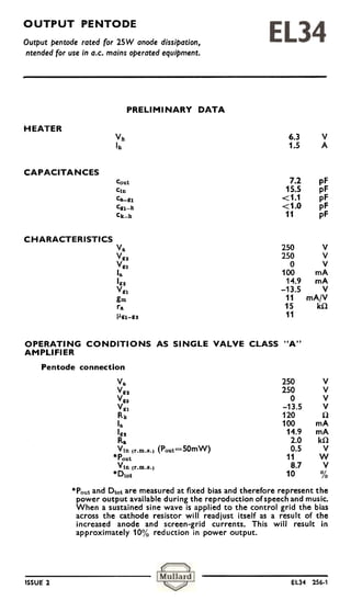
  • 1. OUTPUT PENTODE Output pentode rated for 25W anode dissipation, ntended for use in a.c. mains operated equipment. PRELIMINARY DATA HEATER Vh 6.3 v Ih 1.5 A CAPACITANCES Cout 7.2 pF Cln 15.5 pF C&-gl <1.1 pF Cgl-h <1.0 pF Ck-h 11 pF CHARACTERISTICS Va 250 v v go 250 v Vgs 0 v la 100 mA Igo 14.9 mA Vgl -13.5 V gm 11 mA/V ra 15 kil (.I.gl-gO 11 OPERATING CONDITIONS AS SINGLE VALVE CLASS "A" AMPLIFIER Pentode connection Va 250 V Vg2 250 V Vga 0 V Vg1 -13.5 V Rk 120 (1 la 100 mA Ig2 14.9 mA R. 2.0 k(1 V1n (r.m.B.) (Pout=50mW) 0.5 V *Pout 11 W V1n (r.m.B.) 8.7 V *Dtot 10 % *Pout and Dtot are measured at fixed bias and therefore represent the power output available during the reproduction of speech and music. When a sustained sine wave is applied to the control grid the bias across the cathode resistor will readjust itself as a result of the increased anode and screen-grid currents. This will result in approximately 10% reduction in power output. ISSUE 2 EL34 256-1
  • 2. OUTPUT PENTODE Output pentode roted for 2SW onode dissipotion, intended for use in a.c. mains operated equiPment. OPERATING CONDITIONS FOR TWO VALVES IN PUSH-PULL Distributed load conditions with screen-grid tapping at 43% of primary turns V"J-VRk 430 430 v Rg2 (per valve) 1 1 kO Vg2+VRk 425 425 V 18(0) 2 x 62.5 2 x 62.5 mA 18 (max. sig.) 2x65 2x70 mA Ig2(0) 2x5.0 2x5.0 mA Ig2 (max. sig.) 2x5.1 2x7.5 mA Rk (per valve) 470 470 O V1n(gl-gl) r.m... 32 52 V R8-8 6.6 6.6 kO Pout 20 37 W Dtot 0.8 1.3 % OPERATING CONDITIONS FOR TWO VALVES IN PUSH.PULL Fixed bias Vb 425 375 y "Rg2 1000 470 O Vg2 0 0 y 18(0) 2x30 2x35 mA la (max. sig.) 2x120 2x120 mA Ig2 (0) 2x4.4 2x4.7 mA Ig2 (max. sig.) 2x25 2x25 mA Vg1 -38 -32 y R8-a 3.4 2.8 kO V1n (gi-g 11 r.m.8. 54 45 y Pout 55 44 W Dtot 5.0 5.0 % *Screen-grid resistor common to both valves, These operating conditions apply with a stabilised line voltage and allow for a 25V drop in the primary winding of the output trans- former at maximum signal. If there is an additional drop of 25V in the h.t. line voltage at maximum signal Pout=45W and 36W. The optimum anode-to-anode load under these conditions are 4.0kD. and 3.8kD. respectively. ISSUE 2 EL34 256-2
  • 3. OUTPUT PENTODE Output pentode rated forc25W anode dissipation, intended for use in a.c. mains operated equipment OPERATING CONDITIONS FOR TWO VALVES IN PUSH-PULL With separate screen-grid supply and fixed bias Vb(a) 500 800 V Vb(g2' 400 400 V *Rg2 750 750 !1 Vg:J 0 0 V Ja(O; 2x30 2x25 mA la (max. sig.) 2x125 2x91 mA Ig2(o, 2x4.0 2x3.0 mA Ig2 (max:sig.) 2x25 2x19 mA Vg1 -36 -39 V Ra_a 4.0 11 k!1 VIR (g,-g,) r.m.B. 51 47 V , PC))1~ 70 100 W I Dto1 5.0 5.0 % , *Screen-grid resistor common to both valves. These operating conditions apply with stabilised line voltages and allow for a 2SV drop in the primary winding of the output trans- former at maximum signal. If there is an additional drop of 25V in the line voltages at maximum signal Pout=58W and 90W. The optimum anode-to-anode load under these conditions are 5.0k!1 and 11 kO respectively. OPERATING CONDITIONS FOR TWO VALVES IN PUSH.PULL Cathode bias Vb 375 V *Rg. 470 O tRk 130 O Vg. O V la(ol 2x75 mA la(max.sig.) 2x95 mA Ig.(ol 2x11.5 mA In (max.c5jgr) ! 2 x 22.5 mA Ra_a 3.4 kO V1n(gl-gl) r.m.8. 42 V Pout 35 W Dtot 5.0 % *Screen-grid resistor common tO both valves. tCommon cathode bias resistor. These operating conditions allow for a 20V drop in the primary winding of the output transformer and a 5V drop in the h.t. line voltage at maximum signal. ISSUE 2 EL34 1056.3
  • 4. OUTPUT PENTODE Output pentode rated far 25W anode dissipation, intended for use in a.c. mains operated equipment. OPERATING CONDITIONS AS SINGLE VALVE CLASS "A" AMPLIFIER Triode connection (g2 connected to a, ga to k) Va+VRk 375 v V 0 v R~a 370 O la 70 mA Vgl -26 V Ra 3.0 kO V1n (r.m.s.) (Poul=50mW) 1.7 V Poul 6.0 W V1n (r.m.s.) 18.9 V Dlo1 8.0 % OPERATING CONDITIONS FOR TWO VALVES IN PUSH-PULL Triode connection (g2 connected to a, g3 to k) V,,+VRk 400 430 V V83 0 0 V *Rk 220 t250 .0 I,,(o) 2x65 2x64 mA I" (max. sig.) 2x71 2x67 mA V81 -29 -32 V R"_,, 5.0 10 k.O V1n (81-81)r.m.s. 44 48 V Poul 16 14 W D1o1 3.0 <1.0 % *Common cathode bias resistor. tUn-bypassed. LIMITING VALUES Va(b) max. 2.0 kV Va max. 800 V Pa max. 25 W Pa max. (max. signal speech and music) 27.5 W V lI(b) max. 800 V VII max. 425 V pgo max. 8.0 W Ik max. 150 mA Vn max. (In=+0.3!J.A) -1.3 V Rn-k max. (cathode bias) 700 k.Q Rn-k max. (fixed bias) 500 k.Q Vh-k max. 100 V Rh-k max. 20 k.Q ISSUE 2 EL34 1056.4
  • 5. OUTPUT PENTODE Output pentode roted for 2SW anode dissipation, intended for use in a.c. mains operated equipment. ~ 92 91 a HC q2 h h q3 k Oclal Bas, ISSUE2 EL3~ 1056-5 ~
  • 6. OUTPUT PENTODE Output pentode rated for 25W anode dissiPation, intended for use in a.c. mains operated equiPment. ANODE AND SCREEN-GRID CURRENT PLOTTED AGAINST CONTROL GRID VOLTAGE ISSUS;2 EL34 1056-6
  • 7. OUTPUT PENTODE Output pentode roted for 25W onode dissipation, intended for use in a.c. mains operated equiPment. ~ ~ 0- I > > ."' O "i' """ -' " ..."' ::' > O II I~ ,0.:~.. 0 a.. HE ~ ~ ANODE CURRENT PLOTTED AGAINST ANODE VOLTAGE WITH CONTROL-GRID VOLTAGE AS PARAMETER Vg.=250V ISSUE 2 @ EL34 357.7
  • 8. OUTPUT PENTODE- Output pentode rated for 25W anode dissipation, intended for use in a.c. mains operated equipment. ANODE CURRENT PLOTTED AGAINST ANODE VOLTAGE WITH CONTROL GRID VOLTAGE AS PARAMETER Vg2=360V cW ~ ISSUE 2 EL34 357-8
  • 9. OUTPUT PENTODE Output pentode rated for 25W anode dissipation, intended for use in a.c. mains operated equipment.
  • 10. OUTPUT PENTODE Output pentode rated for 25W anode dissipation, intended for use in a.c. mains operated equipment. ~'(.;.w.J (000000 00000 O Oj)~O~OO--m ;!i , .+~.. I l' .I 0 2 -:1 ~ , -ti :J', I I ~ >-- + ~ ~ ~- -o .-! ~:, 1. »c:~$ :;. ~~.~'!' c :. .. ]~ . & ::r;. , ., ~ ~Ei 05::=. !(VUI)1 0 ~ ~ (..IU,)(I6-I!).!~ ~ o o 0 . ~ N PERFORMANCE OF TWO EL34 IN PUSH-PULL WITH DISTRIBUTED LOAD CONDITIONS. SCREEN-GRID TAPPING AT 43% OF PRIMARY TURNS ISSUE 2 EL34 105610 @
  • 11. OUTPUT PENTODE Output pentode roted for 25W onode dissipotion, intended for use in a.c. mains operated equipment. . ~ c 0 > Q E ° OM ::;. ~: ~ + (vw)I ~ l""'A)U!A ~ 0 . ~ ~Ofo) ...0 ~ 2 PERFORMANCE OF TWO EL34 IN PUSH-PULL WITH FIXED BIAS AND Vb=375V ISSUE 2 e EL.34 1056-1 f
  • 12. OUTPUT PENTODE Output pentode rated for 25W anode dissipation, intended for use in a.c. mains operated equipment. ;; 12 .,"'; " , " (Vw)1 9 9 8 o -~- "' - , ( .."A ) U!A O -0 0 . ~ (010) .O.a ~ ~ PERFORMANCE OF TWO EL34 IN PUSH-PULL WITH FIXED BIAS AND Vb=425V ISSUE 2 EL34 1056-12
  • 13. OUTPUT PENTODE Output pentode rated for 25W anode dissipation, intended for use in a.c. mains operated equipment. PERFORMANCE OF TWO EL34 IN PUSH-PULL WITH SEPARATE ANODE AND SCREEN-GRID VOLTAGE SUPPLIES AND FIXED BIAS V"(b)=SOOV, Vg2(b)=400V ISSUE 2 EL34 256-13 @
  • 14. OUTPUT PENTODE Output pentoderated for 25W anode dissipation, intended for use in a.c. mains operated equiPment. PERFORMANCE OF TWO EL34 IN PUSH-PULL WITH SEPARATE ANODE AND SCREEN-GRID VOLTAGE SUPPLIES AND FIXED BIAS Va(bl=800V. V"(b)=400V ISSUE 2 EL3. 256.11 1@
  • 15. OUTPUT PENTODE Output pentode rated for 25W anode dissipation, intended for use in a.c. mains operated equipment. PERFORMANCE OF TWO EL34 IN PUSH-PULL WITH CATHODE BIAS AND Vb=37SV ISSUE 2 EL34 1056-15 ~
  • 17. OUTPUT PENTODE Output pentode rated for 25W anode dissipation, intended for use in a.c. mains operated equiPment. PERFORMANCE OF TWO EL34 IN PI,JSH-PULL TRIODE CONNECTED ISSUE 2 EL34 1056-17