IoT-based Autonomously Driven Vehicle by using Machine Learning & Image Proce...
Line Follower Final Report
1. LINE-FOLLOWING ROBOTIC CAR
TEAM ARTICULATE, MECHATRONICS
ROBERT BLOSSER, NICK RUSH, PEDRO NUNEZ, VAUGHN
WOODFIELD
FEBRUARY 14, 2016
2. Blosser, Rush, Nunez, Woodfield 1
Abstract
Line-following vehicles are used in a variety of industrial applications, namely in assembly line
manufacturing. Our objective was to design and build a robotic vehicle capable of following and
maintaining position along a solid black line. Mechanical design for our robot includes an original
chassis, pivots, and tie rods. Articulated steering maneuvered by a servomotor control the vehicle’s
trajectory and is driven by a DC motor. An Arduino microcontroller, data logger shield, and a motor
shield are used to control the various mechanical and digital components. A QRTA three-point sensor
array measures reflectance contrast and relays data for processing by the. Program code done using
Arduino IDE instructs the microcontrollers response using a PID derived control system. Values for
coefficients for the PID control were found through an iterative trial and error process. These were Kp
= 0.2, Ki = 0.00015, Kd = 3.5. Intermediate and advanced courses were successfully performed by our
team’s line-follower. The advanced course with small turning radius was beyond our design’s
mechanical limitations.
Contents
Introduction..................................................................................................................................................2
Methodology.................................................................................................................................................4
Initial Design Development.....................................................................................................................4
Construction.............................................................................................................................................5
Programming Code Implementation .....................................................................................................9
QTRA Sensor Implementation.........................................................................................................10
Locomotion and Steering Implementation......................................................................................10
Feedback Control Logic ....................................................................................................................11
Testing Plan............................................................................................................................................12
Results.........................................................................................................................................................13
Mechanical..............................................................................................................................................13
Programming .........................................................................................................................................14
Competition............................................................................................................................................15
Discussion ...................................................................................................................................................16
Conclusion ..................................................................................................................................................18
References...................................................................................................................................................18
Appendix.....................................................................................................................................................19
Team Member Contributions...............................................................................................................23
Competition Tracks...............................................................................................................................24
Line Follower Code................................................................................................................................24
3. Blosser, Rush, Nunez, Woodfield 2
Figure 1: Initial Line Follower Design ..........................................................................................................3
Figure 2: Final Finished Product ...................................................................................................................3
Figure 3: PID Schematic................................................................................................................................4
Figure 4: PID Responses ...............................................................................................................................4
Figure 5: Pololu 150:1 Micro Metal Gearmotor (Source: Pololu.com).........................................................6
Figure 6: Arduino Uno R3 microcontroller (Source: Adafruit.com).............................................................6
Figure 7: Adafruit Motor Shield....................................................................................................................6
Figure 8: TowerPro SG90 Servo (Source: rcshopbd.com)............................................................................6
Figure 9: Pololu QTR-3A Sensor Array (Source: Pololu.com).....................................................................7
Figure 10: Pololu 40x7mm Wheel (Source: Pololu.com) .............................................................................7
Figure 11: Adafruit Data Logger Shield (Source: Adafruit.com)..................................................................8
Figure 12:Microcontroller, Datalogger, Motor Shield Integration................................................................8
Figure 13: Microcontroller and Component Circuit Schematic ....................................................................9
Figure 14: Tie Rods for Steering Mechanism................................................................................................9
Figure 15: Corrected Turning Radius ..........................................................................................................13
Figure 16: Logfile Data 2/8/16 29 ..............................................................................................................14
Figure 17: Logfile Data 2/10/16 21 ............................................................................................................15
Figure 18: Competition Results...................................................................................................................16
Introduction
Line-following robots can be used in many different industries. Manufacturing facilities such as Boeing,
Toyota, and Ford use them to regulate and control product lines (2) (3). Other applications include
delivering medical equipment and supplies in the health care system, or warehouse stocking and shipping
transportation. Amazon uses an army of line-following robots traversing a set path to quickly and
accurately get orders out to customers (4).
A line-following robot is an autonomous robot capable of following a line with relative position.
Traditionally line-following robots include a light sensor array, a microcontroller (e.g. Arduino,
Raspberry Pi), a motor, a power source, and a motor controller or shield. The sensors detect infrared light,
or more specifically, changes in the contrast of reflectance. This information is then processed by a
microcontroller which in turn implements a desired action. The microcontroller processes the data and
sends a signal to a motor control. The motor controllers allow control over the speeds, positions, and
supply voltage to the various motors. These are integrated with the microcontroller and are constantly
communicating with each other based off of inputs and outputs. The microcontroller performs these tasks
through electrical signals, generally voltage changes, generated by its instructed programming and data
inputs (1).
While the main components for line-following robots tend to be similar, the housing or chassis on which
these are built can vary. Commonly skid steering is used to control the trajectory of line-followers. In part
because it allows even large line-followers to have small turning radii. This is important when following
tight turns. Skid steering gets its outstanding turn radius from the use of two motors both turning each
side of the robot independently. Another form of steering is articulated steering comparable to standard
automobiles. Two tie rods attach the tires together and allow them to turn the car in unison.
4. Blosser, Rush, Nunez, Woodfield 3
Being able to produce a robust system that can accomplish a task while reducing complexity and
ultimately cost is the primary goal of our team. In order to properly find a good design our team did a
design study in ME-414, fall semester 2015. The focus for this report was on finding a mechanical system
that would provide a good building platform for all the electrical components, something that would be
cost effective and competitive. The results from the design study showed a clear winner, the final design
that was chosen is presented below in figure 1. Above is presented our initial design this semester, our
team had to make some modifications to stay competitive with other teams. Teams who made use of skid
steering had a significant advantage compared to our design, as we did not have a zero degree turn radius.
We mitigated this factor by making some cutouts on the frame to allow the tires to turn farther. The only
other modification was the light sensor mounting bracket was pushed out slightly further ahead. This was
done to keep the steering mechanism from altering the light readings on the array. Figure 2 shows the
final manufactured line-follower that we created.
As can be noted in our final design in Figure 2, we have a three different boards on this line-follower. The
base board is a micro controller. This is the brains of the system, what processes our code. The micro
controller at its basic form is a collection of components all tied into one system, it includes memory,
input/output pins, and it is all made to work with a simple programming language. Out team chose to go
with an Arduino Uno R3 compatible as one of our team members already owned the board. The low entry
cost and high support for this board made the choice easy. Once a board had been selected we as a team
could choose a programing logic. There are many ways to instruct the micro controller to follow the line,
for our case we settled on Proportional, Integral, Derivative controller also known as PID.
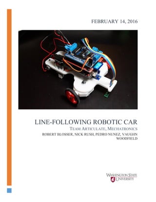
Figure 2: Final Finished Product
Figure 1: Initial Line Follower Design
5. Blosser, Rush, Nunez, Woodfield 4
Our design utilized a feedback control system, specifically a type known as Proportional-Integral-
Derivative control. PID control systems are one of the most common types used in a variety of industrial
applications (5). In a PID control system a reference value called the set-point is a desired value that all
output values would be compared to. Differences between the set-point and measured outputs is the error
of the system. This error is then processed by the control system. The proportional control processed is
the current value (set-point – measured output). The integral control processes previous errors acting as a
counter. The derivative control processes the current error trends and considers future error that may
occur. Coefficients to each of these controls are referred to as Kp, Ki, Kd and are used to give weight to
each control variation in the PID (5). Depending on the output of the system and the type of error each
coefficient’s value can be altered independently until the desire output is acquired. Reference the
schematic in Figure 3 for a visual representation of this control system.
Figure 3: PID Schematic
Advantages to using control systems while we developed the program that would instruct our line-
follower, was a way to iteratively tune inputs and observe the output and its error. The micro-controllers
used are capable of processing data including logging inputs and outputs. Allowing us to find values that
provided the desired behavior. Many industries that employ PID control systems use iteration techniques
paired with statistical error analyses.
Methodology
Initial Design Development
Our design utilized an articulated steering mechanism to control the car’s trajectory. A servomotor
controlled this apparatus. Turning radius of our car needed to be evaluated to understand its limitations.
To calculate the turning radius of our line follower, Eq. 1 was used.
𝑅 =
𝑊
sin( 𝛼)
(Eq. 1)
.
Figure 4: PID Responses
6. Blosser, Rush, Nunez, Woodfield 5
where R is the turning radius, W is the length between wheels, and α is maximum offset angle of
the steering wheel. The turning radius can be seen presented graphically in figure 15.
Propulsion is performed by the single wheel located in the rear of the vehicle. A DC motor with a 150:1
reduction output a maximum of 85 RPM to the driving wheel. Due to the mechanical limitations of
steering and control a stable controlled speed was ideal.
Construction
For our line follower design, our group chose to source parts that were easily replaceable, easy to work
with, reliable, and had sufficient online resources for operating and troubleshooting. We felt that by
choosing parts with these criteria in mind, we would be able to spend more time designing, building, and
optimizing our line follower and less time troubleshooting obscure problems or issues that were unrelated
to the overall objective of this assignment. Since our group already chose to employ unconventional
methods of steering and driving our line follower design, we also felt using off-the-shelf parts would
decrease the number of problems we would encounter. The major components used in the construction of
our line follower design are listed in the table below.
Table 1: Line Follower Components
Component Model Quantity
Micro-Controller Arduino Uno R3 compatible 1
Motor Pololu 150:1 Micro Metal Gear motor 1
Motor Driver Adafruit Motor Shield compatible for Arduino 1
Servo Tower Pro SG90 Micro Servo 1
Light Sensor Array QTR-3A Reflectance Sensor Array 1
Chassis 3D Printed ABS Plastic 1
Wheels Pololu Wheel 40×7mm Pair – Red 2
Batteries Duracell Alkaline 9V Battery Pack Of 2 1
Data Logger Adafruit Data Logging Shield compatible for Arduino 1
7. Blosser, Rush, Nunez, Woodfield 6
To control the motion and line following capabilities of our line follower robot design, our group chose to
use an Arduino Uno R3 compatible microcontroller board, similar to the one pictured on the left. The
Arduino Uno architecture is designed with ease-of-use in mind and has a proven track record as a reliable
and fully supported development controller board. In addition to a robust hardware architecture, Arduino
also provides a fully functional IDE (Integrated Development Environment) which is used to program the
desired functionality of the Arduino Uno microcontroller using C++ code language. Our group was able
to use the functionality of the Arduino Uno along with the provided IDE to fully program the desired
behavior of our line follower robot. To provide our group’s line follower design necessary locomotion,
our group chose to use a geared DC motor from Pololu.com, specifically a 150:1 Micro Metal Gearmotor.
This motor provides a free-run speed of 85 rpm.
To facilitate proper communication between the Arduino Uno and the geared DC motor, our group chose
to use an Adafruit Motor Shield compatible, which is designed specifically to power and control up to
four bi-directional DC motors and two 5V servos using the TI L293D driver chip. (1) The motor shield is
designed around the Arduino Uno architecture and can be placed directly on top of the microcontroller for
simple turn-key implementation. The shield also provides pin-outs for analog pins 0 through 5 which can
be used to attach additional sensors.
Since our design used a single DC motor for
locomotion and a servo to control steering, as well
as an analog IR sensor array, this shield provided us
with all of the capabilities necessary to implement
our design goals. The shield had the added benefit
of accepting an external power supply which could Figure 8: TowerPro SG90 Servo (Source:
rcshopbd.com)
Figure 7: Adafruit Motor Shield
Figure 5: Pololu 150:1 Micro Metal Gearmotor
(Source: Pololu.com)
Figure 6: Arduino Uno R3 microcontroller (Source:
Adafruit.com)
8. Blosser, Rush, Nunez, Woodfield 7
power not only the servo, motor, and sensors, but the microcontroller as well.
The servo our group chose to control the steering mechanism of our line follower robot design was the
Tower Pro SG90 Micro Servo. At only 0.32 oz, the servo provides 180 degrees of rotation and 25 oz.-in.
of torque at 4.8V. (2) With such a small size, our group was able to provide sufficient steering control
while keeping the overall size of our design as compact as possible. The 3-wire interface of the servo also
provided easy installation into the motor shield used to power it.
An integral component of any line follower robot design is the sensor used to detect reflected light off of
a surface. The robot uses this sensor to sense the location of a line by the amount of reflected light, or
more specifically lack thereof, resulting from the contrast of a dark line on a light sheet of paper. Our
group chose to use the Pololu QTR-3A Reflectance
Sensor Array for this capability. The array module uses
three IR LED/phototransistor pairs to emit IR light onto a
surface and then detect the amount of light reflected back.
(3) This information is then sent to the microcontroller
via analog pins which are then interpreted in order to
locate the line in relation to the array and steer the robot
accordingly. Pololu also provides an Arduino code
library for this sensor array, allowing for easier hardware
integration and logic programming. Functions from this
library were used in designing the logic of our group’s
robot design and will be discussed in more detail later in
this report.
The wheels that our line following robot used are also from Pololu.
The Pololu 40x7mm wheel is designed with a “D” shaped female
mate at its central axis which allows for easy attachment of the
wheel onto the company’s wide variety of motors, including the one
used in our design. (4) The size of the wheel was chosen based on
the required turning radius of our design and, with some adjustment
to the line follower chassis, provided an adequate turning radius for
the tracks that our design would be traversing. The provided rubber
tire also gave enough friction so that our line follower design was
able to run on any surface it encountered.
In order to supply enough power to run all of the electronics in our
design, our group chose to use two 9V batteries, wired in parallel.
This ensured sufficient power to run the line follower robot during
extensive testing sessions as well as during the 3-course timed evaluation.
Figure 9: Pololu QTR-3A Sensor Array (Source:
Pololu.com)
Figure 10: Pololu 40x7mm Wheel
(Source: Pololu.com)
9. Blosser, Rush, Nunez, Woodfield 8
The final component of our line follower design was
the Adafruit Data Logging Shield compatible for
Arduino. This shield uses a Real-Time Clock (RTC)
and SD Card reader to allow developers to write data
directly to an SD card for later analysis. It uses the
same design architecture as the Arduino Uno and the
Adafruit Motor Shield, allowing it to be stacked
vertically with those other components for easy
communication and compartmentalization throughout
the entire project. Our group was able to use the data
logger shield to and software code to generate
Comma-Separated Value (CSV) files which stored
sensor data from the reflectance sensor array, steering
rate, and servo position which could then be opened
and analyzed in Microsoft Excel and Matlab. This
data allowed our group to gain a much better
understanding of the behavior of our design during testing, which in turn allowed us to fine-tune our
design’s performance much better than by just relying on visual observations. Some of the data plots
produced from this data will be discussed in more detail later in this report.
Component Integration
The design of the Arduino Uno microcontroller allows for
easy integration of additional electronic components
through the use of “shields” as mentioned in the above
section. This design architecture allowed our group to
combine the Arduino Uno, Motor Shield, and Data
Logger Shield into a single electronics package simply by
stacking one on top of the other so that the digital and
analog IO pins of each individual component connected
them together. In this way, our group was able to avoid
excessive use of jumper wires or solder connections and
helped to prevent unwanted technical troubleshooting.
With the electronics package assembled, we were then able to wire the remaining components to the
appropriate pin-outs on the motor shield. Our design’s two 9V batteries, wired in parallel, were
connected to the external power supply terminals, the 3-wire connection from the micro servo was
attached to the corresponding pins, and the reflectance sensor array was connected to power and Analog
Pins 0, 1, and 2. A toggle switch was also wired in between the power supply and the external power
terminals, allowing for better control of power to the line follower during testing and competition.
Finally, the geared DC motor was connected to one of the four sets of terminals on the shield dedicated
for motors. A schematic of this wiring layout is shown in the figure below.
Figure 11: Adafruit Data Logger Shield (Source:
Adafruit.com)
Figure 12:Microcontroller, Datalogger, Motor Shield
Integration
10. Blosser, Rush, Nunez, Woodfield 9
Figure 13: Microcontroller and Component Circuit Schematic
To operate the steering mechanism of the line
follower, a #10 socket head cap screw was
secured in the servo horn and then attached to the
forward steering bar. In this way, the rotational
movement of the servo, managed by the
microcontroller using a code-implemented PID
controller, would direct the line follower left or
right depending on sensor value readings from
the reflectance array. This steering mechanism is
illustrated in the image shown to the right.
Programming Code Implementation
In order to control our line follower robot, a computer program was needed that could facilitate
communication between our design’s various electronic components. The sensor data gathered by the
reflectance sensor needed to be interpreted by the microcontroller, which would in turn use that data to
control the speed of the DC motor as well as the rotation of the servo. All of this data would also need to
be recorded onto the SD card attached to the data logger shield so that our group could more closely
analyze our results and adjust our feedback control loop accordingly. Unfortunately, no program with all
of these capabilities was available to us, so our group was tasked with writing code that could be used by
the Arduino microcontroller to handle all of these various tasks and ultimately allow our line-following
robot to properly navigate.
Figure 14: Tie Rods for Steering Mechanism
11. Blosser, Rush, Nunez, Woodfield 10
QTRA Sensor Implementation
At the heart of our code was a function and object library provided by Pololu.com, QTRSensors.h, that
we could use to view and interpret the sensor data from the sensor array. This downloadable library,
obtained from code repository Github.com, contained functions that called sensor data from each
individual IR sensor as well as a function that would interpret data from all three sensors to determine the
direction of the line if all three sensors no longer registered where it was.
The sensor array object was called using the command
QTRSensorsAnalog qtra((unsigned char[]) {0, 1, 2},
NUM_SENSORS, NUM_SAMPLES_PER_SENSOR, EMITTER_PIN);
where qtra is the sensor array object, 0, 1, and 2 are the analog pins assigned to the three IR sensors, and
EMITTER_PIN is the pin assigned to the IR LEDs. Once the sensor array object was created, our group
was able to call functions to read the sensor data from the object using the commands
unsigned int position = qtra.readLine(sensorValues);
logfile.print(sensorValues[i]);
where sensorValues[] is an array containing sensor data from each individual sensor and the integer
variable position indicated overall location of the line with respect to the sensor array. These commands
were processed within void loop(void) so that every time the program loop initialized, new sensor
readings were collected. Position, in particular, played a critical role in our code design as it was used to
calculate the feedback error in the PID controller that our group utilized. This variable changes from 0 to
2000 depending on which of the three sensors last detected a dark contrast (e.g. the line). The sensors
determine a rating value of 0 to 1000 where high reflectance (white) is a 0 and low reflectance (black
line) is 1000. Position will have a value of 1000 when sensor 2 (the middle sensor) of the QTRA sensor
array indicates 1000.
Finally, the other primary function used from this library was a calibration function that would measure
the maximum and minimum sensor values, using the command
qtra.calibrate();
This function, called during void setup(void), allowed the sensors to provide accurate data before the main
program loop began, regardless of the surface the sensors were collecting data from.
Locomotion and Steering Implementation
In order to give our line follower robot the ability to move and steer, our group needed to implement the
proper commands in our code. This required the inclusion of two function libraries, Servo.h and
AFMotor.h, both obtained from Github.com. These libraries provided functions that were easily
implemented and allowed our line follower to move and react to the sensor data it was receiving from the
IR sensor array.
To control the servo steering mechanism, we included a servo object and assigned it to a digital pin on the
Arduino Uno using the command
Servo myservo;
myservo.Attach(9);
12. Blosser, Rush, Nunez, Woodfield 11
where myservo is the declared servo object and myservo.Attach(9) assigns the created servo object to pin
9 on the Arduino Uno. Once defined and assigned, rotating the servo on our line follower robot was a
simple matter of assigning a numerical position using the command
myservo.write(pos);
where pos was a discrete angular position. This method of adjusting the servo to steer the line follower
robot was also incorporated in the feedback control method we used to navigate the line, which is
discussed later in this report.
Providing forward movement to the line follower using the DC motor was also fairly straightforward. By
declaring the DC motor object in the code using the command
AF_DCMotor motor3(3);
we create motor3 as a DC motor object and assign it to pin 3 on the Arduino Uno. AFmotor.h also
provides functions for easily controlling speed and direction of the DC motor so our group was able to
assign a speed and direction using the commands
motor3.run(FORWARD);
motor3.setSpeed(MShigh);
where FORWARD indicates that the DC motor should rotate in a clockwise direction, and
setSpeed(MShigh) sets the speed of the motor using values 0-255, or in our case, a preset variable based
on sensor data.
Feedback Control Logic
In order to ensure that our robot design correctly followed a line along a curving track, our group chose to
implement feedback control logic, specifically using PID controller schema. This was implemented using
the following lines of code
int error1 = position - 1000;
double steerRate = (Kp * error1 + Ki * integral + Kd * (error1 –
lastError))*SRhigh/1000;
lastError = error1;
integral += error1;
pos += steerRate;
myservo.write(pos);
where error1 is error calculated using the position value from the qtra sensor array object, steerRate is the
rotational rate of change of the servo, lastError keeps track of the previously calculated error for future
comparison, and integral sums the error of each iteration. The new static angular position of the servo is
then assigned by adding steerRate to the previous position, pos.
At the onset of the program, error1 was set to 0. When the program entered the loop(void), error1
became a comparison between position and our set point of 1000. This determined our set point for our
PID control. When sensor 2 is 1000 and position is at 1000, the error (error1) is 0. The PID interprets the
error and adjust in three ways as discussed in PID theory. A more in depth explanation of each of the PID
coefficients as well as the values our group used in our line follower code is displayed in the table below.
13. Blosser, Rush, Nunez, Woodfield 12
Table 2: PID Variants
Control
Variant
Description Final
Coefficient
Value
Proportional Kp*error1: The proportional coefficient scaled a response based on the
current error. Kp was determined through iteration. Information
interpreted from plots and data acquired by our data logger allowed us
to home in on a working value.
0.2
Integral Ki*integral: The integral coefficient scaled a response on past errors by
accumulating values of error1. Ideally, this accumulation would have an
average of 0 since error1 can have both a negative and positive value.
Ki is a small value because value because it includes a small time step
(< 1 second) by multiplication. Because the integral object can rapidly
grow, a normalization of this control variant is required.
0.00015
Derivative Kd*(error1-lastError): The derivative coefficient scaled a response for
expected/desired future error. In the first iteration of the loop, lastError
is set to a value of 0. After the initial iteration of the loop, the value of
error1 is stored in lastError. These two values are then compared by the
program in the loop. This allows the control to account for how it is
behaving and the coefficient scales a response to attain the desired
behavior. As with the other variants, it is desired that the difference of
errror1-lastError is 0. It can be observed that the value of Kd is much
greater when compared to Kp and Ki. The reason for this contrast is
because Kd accounts for a division by the small time step.
3.5
The entire result of the PID control is scaled down by a factor 1000. This scaled down result is then stored
in an object called steerRate which is defined as a double to allow for precision steering. Values stored in
steerRate dictate to the servomotor through the microcontroller how much to adjust to maintain position
along the line. This is done by adjusting the value of the pos variable which tells the servomotor what to
do.
Testing Plan
In order to fully understand what our code is doing and how modifications affect it, our team decided to
come up with a testing plan to rank different codes. We used a method that would allow us to see what
types of effect our code was producing on our line follower. The original and simplest idea was to simply
time how long it took to traverse a course and give it a ranking ourselves. This however lends itself to
self-bias. We may unknowingly introduce error when ranking our system and thus the need for a better
approach was created. Next we introduced a data logger shield into the microcontroller. Recording our
position and our sensor values provided means to be able to generate plots that indicate how often we
were on the line. We were able to accomplish the data logging by adding a shield to our Arduino board as
can be seen in Figure 2. How this shield works is explained in the construction section of this report, we
will briefly touch base on it in this section. This shield accepts a SD card and can be programmed into the
Arduino code to record data using pre-existing libraries. This allowed our team to plot the traversal data
and get a clear image of how the line follower followed the course. These plots will be further explained
in the results section of this report.
14. Blosser, Rush, Nunez, Woodfield 13
Once this data logging shield was installed testing was greatly simplified. With the shield on we could run
as many different codes as we desired and always pull up the corresponding data set. We have included a
selection of these charts in our appendix, please refer to our appendix subsection “Testing plots”. The
visual representation of the data made troubleshooting much simpler as a result. On multiple occasions we
had issues with the line follower completely doing the wrong thing, having these plots made it so that we
could quickly identify the source of the issue and try to resolve it. Knowing exactly how the line follower
was responding allowed us to hone in our PID code to a level that allowed our line follower to be
competitive.
Results
Mechanical
As the line following car traversed the line the QTR-3A reflectance sensor array detects the line’s
presence. Sensory data is fed to the Arduino micro-controller which is processed by the uploaded
program. The servomotor controlling the steering mechanism rotates to maintain position along the line.
Rate of rotation of the servomotor and effectively the steering is dependent on how far away the array
indicates the line follower is from the line. The further off course the car was, the more compensation to
correct its trajectory was required.
The D.C. gear motor output was controlled by the micro controller as well. Because the motor outputted
only 85 RPM, maximum speed was selected and maintained through the operation.
A turning radius of 4.6 inches was possible for our design. This differs from our initial radius. In order to
improve this feature, material was removed from the chassis that interfered and inhibited turning.
Removing material from the steering tie rods attached to the servomotor also increased the turning
capability.
Figure 15: Corrected Turning Radius
15. Blosser, Rush, Nunez, Woodfield 14
Our design successfully completed the intermediate and advanced course with relative ease. However, the
expert course presented challenges that ultimately proved to be too much for the design to resolve.
Turning radiuses of the advanced course fell beyond the mechanical limitations of the steering
mechanism.
Table 3: Mechanical Results
Parameter Value
Turning Radius 4.6 inch
Motor Speed 85 RPM
Max. Vehicular Speed 7 in/s
Programming
Figure 14 shows data for direction and steer rate over time for an early iteration of the control system.
This control system only contains proportional and derivative terms and the values for each iteration are
shown above each plot. When the sensor array was completely off to one side of the line, it produced a
direction value of 0. Alternatively, when the sensor array was completely off to the other side of the line,
it produced a direction value of 2000. A direction value of 1000 was produced whenever the sensor was
centered on the black line. By interpreting the Direction plot in Figure 13, it can be seen that the sensor
was off the line the majority of the time. This is because the direction values are largely either 0 or 2000.
The faint band across the middle at a direction value of 1000 represent when the sensor was
instantaneously on the line. The Steer Rate plot in Figure 13 shows that the steer rate was almost
constantly maxing out at the limits set for it of positive and negative 10.
-
Figure 16: Logfile Data 2/8/16 29
After further iterations of values for Kp, Kd, and removing steering limits, the line follower was behaving
more closely to how it was intended to perform. The Direction plot in Figure 14 shows that the sensor
was not off the line near as much as the earlier iteration shown in Figure 13. It also shows that there were
many more instances of the sensor being partially on the line. This is represented by the data not
associated with direction values of 0, 1000, and 2000. The goal at this point was to further reduce the
16. Blosser, Rush, Nunez, Woodfield 15
oscillations from crossing the line back and forth. To do this, an integral term was added to the steerRate
function. More information on this PID function can be found in the results section.
Figure 17: Logfile Data 2/10/16 21
After adding the integral term and optimizing the values of Kp, Ki, and Kd, the line follower still oscillated
but the amplitude of these oscillations were very small. Looking at the Steer Rate plot in Figure 15, it can
be seen that there was often a steer rate of 0. This does not mean that the wheels were straight at those
instances, but that they were not changing at those times.
Competition
The first semester of this project we were heavily focused on all of the mechanical aspects of our line
follower. We understood that something things such as turning radius, speed, and battery capacity had to
change at the end of our last design study. The thoroughness of that report allowed us to focus on the
coding part of this project for the second semester. This semester we were able to effectively come in re-
design, build, and test with very little time lost. The addition of the data traversal plots, allowed our group
to keep data storage of what worked and didn’t work in the past making each test run extremely valuable.
This methodical, scientific approach to testing allowed us to greatly improve upon our original code and
create something that was truly competitive, even though it uses articulated steering. This is proven in
figure 13 presented below.
17. Blosser, Rush, Nunez, Woodfield 16
Figure 13, shows the final competition results from our line follower. As can be noted we had a
completed score of 92/100. We were able to quickly complete both the intermediate and advance course
with only one intervention, however we were not able to complete the expert course. The intermediate
course was complete in just 27 seconds with no intervention, unfortunately we do not have class data to
compare against, but this was a fast time. For the advanced section we have no time data recorded other
than one intervention, once again a good result. The expert course was not completed as our turning
radius was too large for the tight turns introduced. Without no pre-existing knowledge of the expert
courses turns we designed our steering ability, which proved to be our design’s challenge. We were able
to make it to the first checkpoint without intervention.
Discussion
Construction of our line-follower car presented a few challenges. Our largest challenge was the steering
mechanism. Computer models demonstrated that our steering mechanism was functional, however,
interference due to the fasteners became an issue during actual construction. This was especially true with
the wheel pivots. Shoulder bolts that allowed the pivots to rotate elevated slightly above the initial
countersink and prevented the steering mechanism from moving past its position. Countersinks that
allowed the shoulder bolt head to sink deeper had to be made.
Another issue that arose with the steering mechanism were the nuts and bolts that attached the tie rods to
the pivots. The nuts holding the tie rods in position would gradually be loosened and eventually fall off
after repeated motions from the steering. Stop nuts with a nylon washer implanted were used to solve and
prevent this issue from occurring.
In order to improve the fluid motion of the steering mechanism the surfaces that made contact between
the wheel pivots, tie rods and the chassis were sanded down. This procedure allowed for less resistance
against the steering mechanism and servomotor and allowed for a quick more fluid response.
Our initial code instructing the steering mechanism used values from the QTRA sensory array to produce
ranges of reflectance. The position object was still used as in our final PID control however it was
processed differently. In the initial code, the object pos was told to count in specified increments related
to the range being read. An example of this below shows how this was done.
// adjust servo steering based on QTRA position values
Figure 18: Competition Results
18. Blosser, Rush, Nunez, Woodfield 17
if (position >= 1800)
{
pos += SRhigh;
myservo.write(pos);
delay(1);
}
else if (position >= 1500 && position < 1800)
{
pos += SRmid;
myservo.write(pos);
delay(1);
The first issue that developed with this approach was a counter error. There was no limit on the pos
counter and if the line-follower was off the line for too long it would get into high values before coming
back down and appear stuck. Code that prevented this from occurring needed to be developed. On the
same vein, ranges using greater than, less, or equal to statements had to be used as the reflectance center
would occasionally not read the expected exact values. Below is an example of how the infinite count
issue was solved.
if (pos > 120)
{
pos = 120;
myservo.write(pos);
delay(1);
}
else if (pos < 0)
{
pos = 0;
myservo.write(pos);
delay(1);
}
However, after many trials of working and changing the position ranges and counter increments for pos
the code was still not working as well as we had hoped. After several attempts to resolve this code, it was
eventually scrapped and our team then integrated coding for PID control.
When we first changed the code we used only a PD control. Initially the control did not have the integral
variant. After trial and error and additional research on PD and how they are used in line-follower
designs, an integral control variant was introduced. This provide incremental control of the output as well
as producing more finite maneuvers.
In future use of the PID control, we will have the code determine the time step as opposed to manually
integrating the time step with the PID coefficients. This could be done use the millis() function that the
Arduino IDE provides and determining the time step of an iteration of a loop. This would provide more
precise means to determining the PID coefficient values.
Competition day for the line-followers was a success. Our line-follower completed both the intermediate
and advanced courses. The intermediate course was passed with no instances of intervention while the
advanced course was passed with one. While traversing the figure 8, the discontinuity where the lines
19. Blosser, Rush, Nunez, Woodfield 18
cross briefly confused our line follower and it lost track of its position. Resetting at a checkpoint allowed
our line-follower another opportunity. On the second attempt it completed the advanced course.
The expert course presented a challenge however. Until the first check point, our line-follower was able to
hold its position along the line. However, it encountered an adjacent line that sensor array detected as it
traveled a tight radius that was mechanically beyond its limits. This caused the line-follower to skip a
portion of the track. It was in the expert course where our mechanical disadvantage to skid steering line-
followers became too much to overcome.
There are many applications of an articulated steering line-follower. If it a design similar to ours was to
be used in assembly line it would provide more stability. This would be important in application where
fragile or hazardous loads were being worked with. Engineers must consider the turning radiuses and
limitations of the areas such line-followers would be used in. In factories with small amounts of space to
work with, articulated steering may not be ideal. However, if space is not an issue and efficiency and
stability are, then a design similar to ours would work well.
Conclusion
Microcontrollers and respective accessories provide means to control input and outputs in the forms of
analog to digital, digital to digital, and digital to analog. In our project we used the ability of a
microcontroller and its components to program and operate a line-following vehicle.
Our expectations for this project was to acquire precise and accurate control of the position of the line-
follower as it traversed the line. However due to oscillations and error in the way the program told the
microcontroller to behave, we were unable to acquire ideal results. Given more time and more
understanding in future projects, we do believe our design is capable of much more fluid control as it
maintains its position. Additions and further alterations discussed previously would be fundamental in
acquiring these ideal results.
However, the program and mechanical features operated within expectations and our design was able to
satisfy the needs of the competition.
Results and implications of our design demonstrate that a design like ours’ is feasible as a line-follower.
As discussed limitations set by the workspace and environment would play into its effectiveness.
References
1. Toyota Motor Corp. Toyota production system. Toyota-Global. [Online] [Cited: 02 11, 2016.]
http://www.toyota-global.com/company/vision_philosophy/toyota_production_system/.
2. GEAR, JASON PAUR. Long Shunned, Robots Finally Infiltrate Boeing’s Assembly Line. Weird.com.
[Online] 06 14, 2013. [Cited: 02 11, 2016.] http://www.wired.com/2013/06/boeing-robots-777/.
20. Blosser, Rush, Nunez, Woodfield 19
3. Knight, Will. Inside Amazon’s Warehouse, Human-Robot Symbiosis. MIT Technology Review.
[Online] [Cited: 02 11, 2016.] https://www.technologyreview.com/s/538601/inside-amazons-warehouse-
human-robot-symbiosis/.
4. Deepak Punetha, Neeraj Kumar, Vartika Mehta. Development and Applications of Line Following
Robot Based Health Care Management Systems. ijarcet.org. [Online] August 2013. http://ijarcet.org/wp-
content/uploads/IJARCET-VOL-2-ISSUE-8-2446-2450.pdf.
5. National Instruments. PID Theory Explained. National Instruments Products & Services. [Online]
National Instruments, March 29, 2011. http://www.ni.com/white-paper/3782/en/.
6. Adafruit.com. Adafruit Motor/Stepper/Servo Shield for Arduino. Adafruit.com. [Online] [Cited:
February 12, 2016.] https://www.adafruit.com/products/81.
7. Servodatabase.com. TowerPro SG90 Servo. Servodatabase.com. [Online] [Cited: February 13, 2016.]
http://www.servodatabase.com/servo/towerpro/sg90.
8. Pololu.com. QTR-3A Reflectance Sensor Array. Pololu.com. [Online] [Cited: February 12, 2016.]
https://www.pololu.com/product/2456.
9. —. Pololu Wheel 40×7mm Pair - Red. Pololu.com. [Online] [Cited: February 13, 2016.]
https://www.pololu.com/product/1453.
10. Bearugard, Brett. Project Blog. Brett Bearugard. [Online] April 15, 2011.
http://brettbeauregard.com/blog/2011/04/improving-the-beginners-pid-introduction/.
11. Adafruit. Using DC Motors. Learn Adafruit. [Online] Adafruit, August 27, 2012.
12. tdicola. GitHub Adafruit Librarys. GitHub. [Online] 2015.
Appendix
Data Logging Plots
24. Blosser, Rush, Nunez, Woodfield 23
LogfileData2/8/16
10
LogfileData2/8/16
11
Team Member Contributions
Nick Rush Initial design development and modification, design
and implementation of code and data logging system,
extensive troubleshooting and testing, electronics
package construction and development, Methodology
(Construction and Programming)
Scott Woodfield Design changes, Basic construction, part acquisition,
DC motor program, testing and troubleshooting,
debugging, PID research, Intro, Design development
and program development in Methodology, mechanical
in Results, Discussion, Conclucsion, Abstract
Robert Blosser
Pedro Nunez Introduction, Results, Methodology, Conclusion, Basic
construction, Testing, Troubleshooting, Debugging.
25. Blosser, Rush, Nunez, Woodfield 24
Competition Tracks
Figure 19: Basic and Intermediate Curses
Figure 20: Advanced Course
Line Follower Code
*It should be noted that the code used to write data to the data logger shield was taken from the example
code provided with the SD.h library from Adafruit.com, hosted on Github.com at:
https://github.com/adafruit/SD
#include <SD.h>
#include <SPI.h>
#include <Wire.h>
#include <RTClib.h>
#include <QTRSensors.h>
#include <Servo.h>
#include <AFMotor.h>
// how many milliseconds between grabbing data and logging it. 1000 ms is once a
second
#define LOG_INTERVAL 1 // mills between entries (reduce to take more/faster data)
// how many milliseconds before writing the logged data permanently to disk
// set it to the LOG_INTERVAL to write each time (safest)
26. Blosser, Rush, Nunez, Woodfield 25
// set it to 10*LOG_INTERVAL to write all data every 10 datareads, you could lose up
to
// the last 10 reads if power is lost but it uses less power and is much faster!
#define SYNC_INTERVAL 1000 // mills between calls to flush() - to write data to the
card
uint32_t syncTime = 0; // time of last sync()
#define ECHO_TO_SERIAL 1 // echo data to serial port
#define WAIT_TO_START 0 // Wait for serial input in setup()
// the digital pins that connect to the LEDs
#define redLEDpin 2
#define greenLEDpin 3
#define Kp 0.2 // Kp < Kd
#define Kd 3.5 // steerRate = (Kp * error1 + Ki * integral + Kd * (error1 -
lastError))*SRhigh/1000;
#define Ki 0.00015
#define SRhigh 10 //Steering Rate
#define SRmid 3
#define SRlow 1
#define MShigh 255 //Motor Speed
#define MSmid 255
#define MSlow 255
AF_DCMotor motor3(3); //define motor on channel 3 with 1kHz default
RTC_DS1307 RTC; // define the Real Time Clock object
// for the data logging shield, we use digital pin 10 for the SD cs line
const int chipSelect = 10;
// the logging file
File logfile;
void error(char *str)
{
Serial.print("error: ");
Serial.println(str);
// red LED indicates error
digitalWrite(redLEDpin, HIGH);
while(1);
}
// REFLECTANCE SENSOR INITIALIZATION
#define NUM_SENSORS 3 // number of sensors used
#define NUM_SAMPLES_PER_SENSOR 4 // average 4 analog samples per sensor reading
#define EMITTER_PIN 2 // emitter is controlled by digital pin 2
// sensors 0 through 5 are connected to analog inputs 0 through 5, respectively
QTRSensorsAnalog qtra((unsigned char[]) {0, 1, 2},
NUM_SENSORS, NUM_SAMPLES_PER_SENSOR, EMITTER_PIN);
unsigned int sensorValues[NUM_SENSORS];
// SERVO INITIALIZATION
Servo myservo; // creates servo object to control a servo
int pos = 60; // stores servo position in degrees 0 to 180
int lastError = 0;
int integral = 0;
27. Blosser, Rush, Nunez, Woodfield 26
void setup(void)
{
Serial.begin(9600);
Serial.println();
// use debugging LEDs
pinMode(redLEDpin, OUTPUT);
pinMode(greenLEDpin, OUTPUT);
#if WAIT_TO_START
Serial.println("Type any character to start");
while (!Serial.available());
#endif //WAIT_TO_START
// initialize the SD card
Serial.print("Initializing SD card...");
// make sure that the default chip select pin is set to
// output, even if you don't use it:
pinMode(10, OUTPUT);
// see if the card is present and can be initialized:
if (!SD.begin(chipSelect)) {
error("Card failed, or not present");
}
Serial.println("card initialized.");
// create a new file
char filename[] = "LOGGER00.CSV";
for (uint8_t i = 0; i < 100; i++) {
filename[6] = i/10 + '0';
filename[7] = i%10 + '0';
if (! SD.exists(filename)) {
// only open a new file if it doesn't exist
logfile = SD.open(filename, FILE_WRITE);
break; // leave the loop!
}
motor3.setSpeed(50); //Begins moving motor
}
if (! logfile) {
error("couldnt create file");
}
Serial.print("Logging to: ");
Serial.println(filename);
// connect to RTC
Wire.begin();
if (!RTC.begin()) {
logfile.println("RTC failed");
#if ECHO_TO_SERIAL
Serial.println("RTC failed");
#endif //ECHO_TO_SERIAL
RTC.adjust(DateTime(__DATE__, __TIME__));
}
logfile.print("Kp: ");
logfile.print(Kp);
logfile.print(" Ki: ");
logfile.print(Ki,6);
logfile.print(" Kd: ");
logfile.println(Kd);
28. Blosser, Rush, Nunez, Woodfield 27
logfile.print(" SRhigh: ");
logfile.println(SRhigh);
logfile.print(" SRmid: ");
logfile.println(SRmid);
logfile.print(" SRlow: ");
logfile.println(SRlow);
logfile.print(" MShigh: ");
logfile.println(MShigh);
logfile.print(" MSmid: ");
logfile.println(MSmid);
logfile.print(" MSlow: ");
logfile.println(MSlow);
logfile.println("millis,stamp,datetime,sensor1,sensor2,sensor3,direction,steerRate");
#if ECHO_TO_SERIAL
Serial.println("millis,stamp,datetime,sensor1,sensor2,sensor3,direction,steerRate");
#endif //ECHO_TO_SERIAL
// If you want to set the aref to something other than 5v
//analogReference(EXTERNAL);
/////////////////////// IR SENSOR INITIALIZATION ///////////////////////
pinMode(0,INPUT);
delay(500);
pinMode(13, OUTPUT);
digitalWrite(13, HIGH); // turn on Arduino's LED to indicate we are in
calibration mode
for (int i = 0; i < 400; i++) // make the calibration take about 10 seconds
{
qtra.calibrate(); // reads all sensors 10 times at 2.5 ms per six sensors
(i.e. ~25 ms per call)
}
digitalWrite(13, LOW); // turn off Arduino's LED to indicate we are through with
calibration
// print the calibration minimum values measured when emitters were on
for (int i = 0; i < NUM_SENSORS; i++)
{
Serial.print(qtra.calibratedMinimumOn[i]);
Serial.print(' ');
}
Serial.println();
// print the calibration maximum values measured when emitters were on
for (int i = 0; i < NUM_SENSORS; i++)
{
Serial.print(qtra.calibratedMaximumOn[i]);
Serial.print(' ');
}
Serial.println();
Serial.println();
delay(1000);
//////////////////////////////////////////////////////////////////////////////////
myservo.attach(9); // attaches the servo on pin 9 to the servo object
}
void loop(void)
{
DateTime now;
// delay for the amount of time we want between readings
delay((LOG_INTERVAL -1) - (millis() % LOG_INTERVAL));
29. Blosser, Rush, Nunez, Woodfield 28
digitalWrite(greenLEDpin, HIGH);
// log milliseconds since starting
uint32_t m = millis();
logfile.print(m); // milliseconds since start
logfile.print(", ");
#if ECHO_TO_SERIAL
Serial.print(m); // milliseconds since start
Serial.print(", ");
#endif
// read calibrated sensor values and obtain a measure of the line position from 0 to
2000
// To get raw sensor values, call:
// qtra.read(sensorValues); instead of unsigned int position =
qtra.readLine(sensorValues);
unsigned int position = qtra.readLine(sensorValues);
// print the sensor values as numbers from 0 to 1000, where 0 means maximum
reflectance and
// 1000 means minimum reflectance, followed by the line position
for (unsigned char i = 0; i < NUM_SENSORS; i++)
{
logfile.print(sensorValues[i]);
logfile.print(',');
#if ECHO_TO_SERIAL
//Serial.print(m);
Serial.print(sensorValues[i]);
Serial.print('t');
#endif
}
//Serial.println(); // uncomment this line if you are using raw values
logfile.print(position);
logfile.print(",");
#if ECHO_TO_SERIAL
Serial.print(position); // comment this line out if you are using raw values
#endif
motor3.run(FORWARD); // turn it on going forward
// Steering Limit
if (pos > 120)
{
pos = 120;
myservo.write(pos);
delay(1);
}
else if (pos < 0)
{
pos = 0;
myservo.write(pos);
delay(1);
}
// Motor Speed
if ((pos >= -3 && pos <=40) || (pos >= 80 && pos <= 123))
{
motor3.setSpeed(MShigh); //motor speed for extereme steering range
}
else if ((pos > 40 && pos < 52) || (pos > 68 && pos < 80))
{
motor3.setSpeed(MSmid); //motor speed for mid steering range
30. Blosser, Rush, Nunez, Woodfield 29
}
else if (pos >= 52 && pos <=68)
{
motor3.setSpeed(MSlow); //motor speed for low steering range
}
// PID Controller Logic
///////////////////////////////////////////////////////////////////////
int error1 = position - 1000;
double steerRate = (Kp * error1 + Ki * integral + Kd * (error1 -
lastError))*SRhigh/1000;
lastError = error1;
integral += error1;
pos += steerRate;
myservo.write(pos);
//////////////////////////////////////////////////////////////////////////////////////
/////////
logfile.print(steerRate);
logfile.println(",");
Serial.println(pos);
digitalWrite(greenLEDpin, LOW);
// Now we write data to disk! Don't sync too often - requires 2048 bytes of I/O to
SD card
// which uses a bunch of power and takes time
if ((millis() - syncTime) < SYNC_INTERVAL) return;
syncTime = millis();
// blink LED to show we are syncing data to the card & updating FAT!
digitalWrite(redLEDpin, HIGH);
logfile.flush();
digitalWrite(redLEDpin, LOW);
}